Input Devices
Week 11's assignment
Specific material and softwares used during this assignment
- Machine : CNC mill for the fabrication of the PCB
- Software :
- Arduino IDE to write the program and read it
- Eagle to edit the schematics and board files
- V-Carve for the G-code
- Processing to read the data
- Software :
- Arduino IDE to write the program and read it
- Eagle to edit the schematics and board files
- V-Carve for the G-code
- Processing to read the data
 Our other instructor, Matthieu, suggested us that it would be a good idea to build our own Arduino board, a "fabDuino", which would then allow us to test and use as many inputs and outputs as we want. It would then be very usefull for the weeks to come and of course for our final project. So this is what I will try to do.
My week will be devided in three parts :
1 - Making the fabDuino and adding an input
2 - Writing the program
3 - Reading it
It will be quite a dense week but it will be fun and very usefull for the next weeks, like I said !
1 - Making the fabDuino
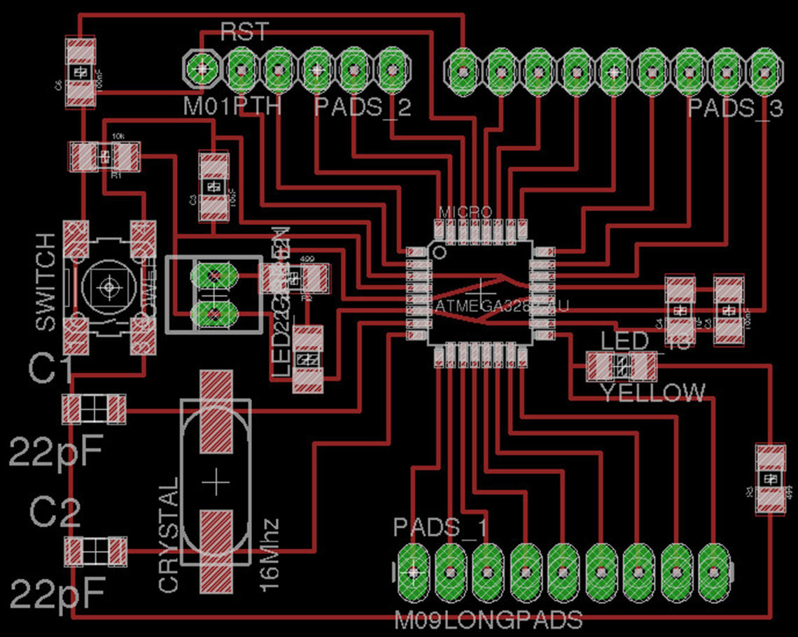
For the fabrication of the board, I decided to reproduce a "Satchakit". The big advantage of this board for me is that it is 100% compatible with Arduino code and libraries. In fact the board is recognized as an Arduino Uno by the IDE, so it will be exactly the same as using an Arduino Uno, which is the thing I'm the most comfortable with for the moment. I think this will be for a big time-saver because I already had a lot o trouble trying to burn and program my previous circuits and I don't want to fall behind too much. There is also some useful info here about the Satchakit.Here is the schematic of the latest version of it :
 These are the settings used in the Fabmodule, with a 1/64 end mill (0.39mm) :
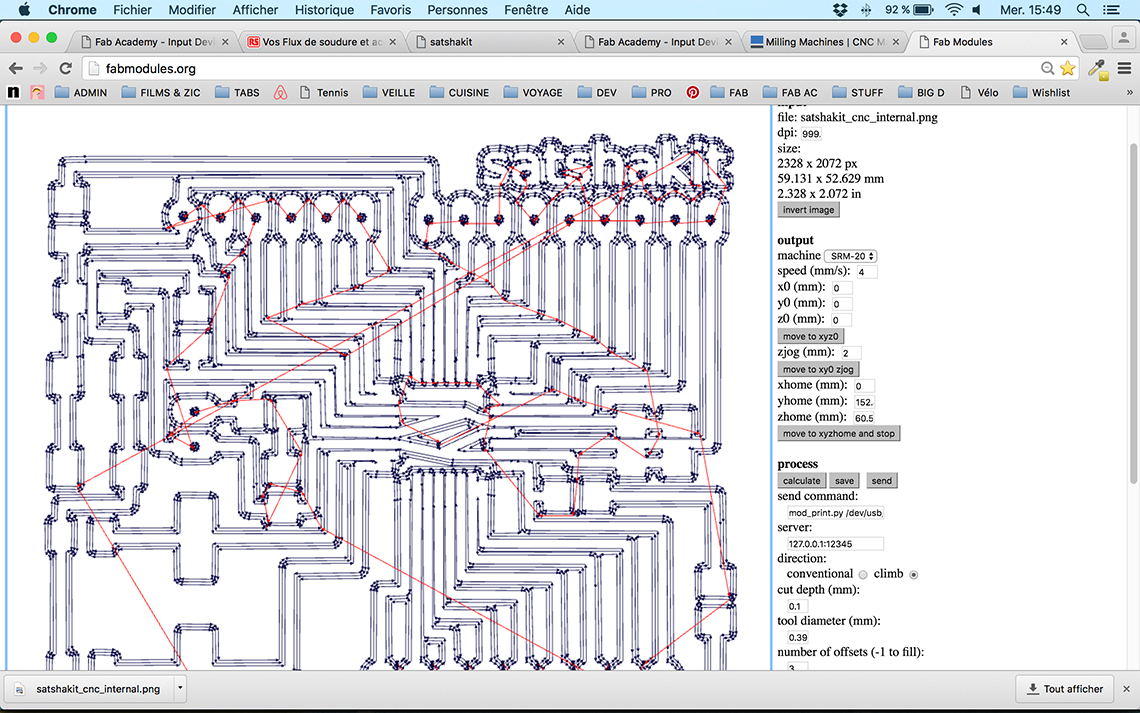 And here is the milled PCB. This is actually the first PCB that has been milled with the new Roland Monofab we recieved recently, which is a great improvement and will be much easier for us in the future :
 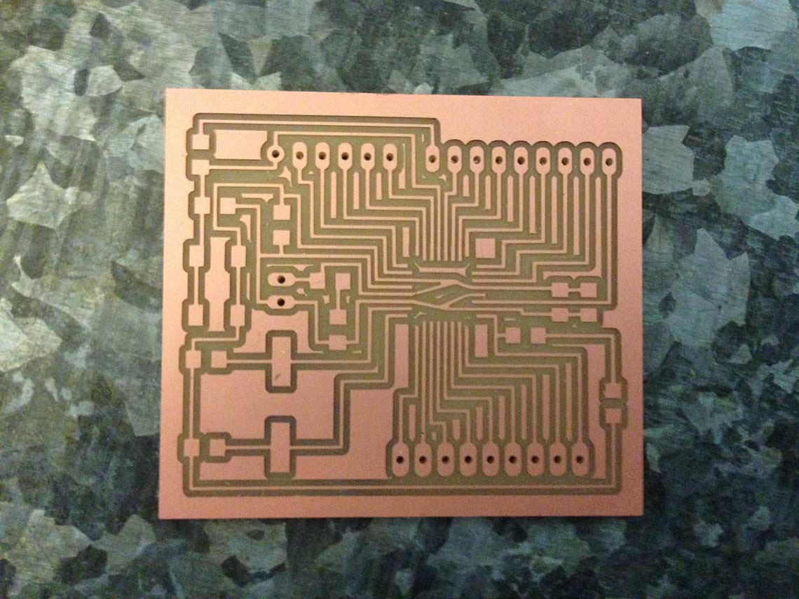 And my Satchakit once all the components soldered :
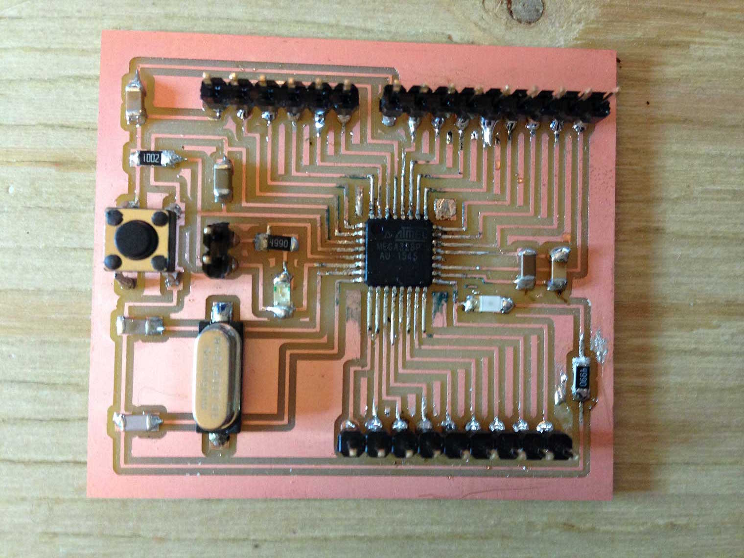 Once the circuit ready, I juste have to use my original Arduino board to burn the Satchakit, because we still don't have a working ISP at the lab...
2 - Writing the program
First version of the program
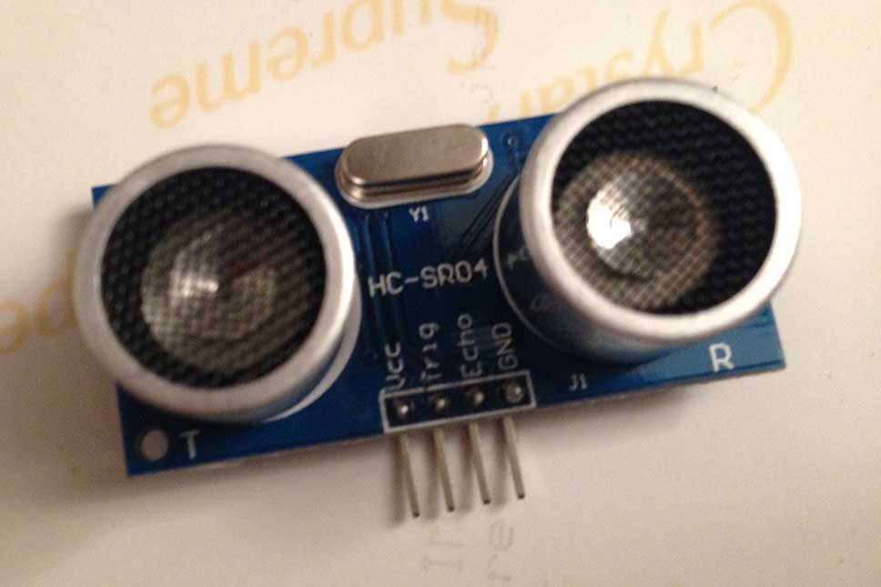
I began to write my program using an Arduino UNO with the HC-SR04 and the Piezo. The first version is very simple and I am not very pleased with the sound effect of the alarm. Also, for the moment I am not able to read any data on the serial monitor. But it is just a test and it works.Here's the code :
    #define trigPin 13
    #define echoPin 12
    #define buzzer 11

    void setup() {
      pinMode(trigPin, OUTPUT);
      pinMode(echoPin, INPUT);
      pinMode(buzzer, OUTPUT);
    }

    void loop() {
      long duration, distance;
      digitalWrite(trigPin, LOW);
      delayMicroseconds(2);
      digitalWrite(trigPin, HIGH);
      delayMicroseconds(10);
      digitalWrite(trigPin, LOW);
      duration = pulseIn(echoPin, HIGH);
      distance = (duration/2) / 29.1;
      if (distance < 5) {
        digitalWrite(buzzer ,HIGH);
    }
      else {
        digitalWrite(buzzer ,LOW);
      }

    }
...And a little test on the Arduino Uno to make sure it works :
Second version of the program
Now I wanted to have a nicer sound effect, and more importantly I wanted to be able to read the data captured by the sensor, so I simply modified my sketch using thetone function and added the serial communication.
    #define trigPin 13
    #define echoPin 12
    #define buzzer 11

    void setup() {
      Serial.begin (9600);
      pinMode(trigPin, OUTPUT);
      pinMode(echoPin, INPUT);
      pinMode(buzzer, OUTPUT);
    }

    void loop() {
      long duration, distance;
      digitalWrite(trigPin, LOW);
      delayMicroseconds(2);
      digitalWrite(trigPin, HIGH);
      delayMicroseconds(10);
      digitalWrite(trigPin, LOW);
      duration = pulseIn(echoPin, HIGH);
      distance = (duration/2) / 29.1;
      Serial.println(distance);
     //read the distance value. If <5cm, the piezo will produce a tone at 262mHz
      if (distance <5) {
        tone(buzzer,262);
    }
     //stop the tone function on the specified pin when distance is higher than 5cm
      else {
        noTone(buzzer);
      }
    }
Once the sketch uploaded, it works like this. This time I used the Satchakit directly ! (the Arduino is there just because I needed the attached breadboard):
3 - Reading the data
Arduino Serial Plotter
Now that I have my board and my code ready, I can read the data ! I want to test two different solutions. The first one is really simple : using the newly implemented Arduino Plotter to look at the mesurements taken by the sensor, and see how it reacts :Basically, we can see that the graph reacts to the movements of my hand. In the beginning my hand is not in the way so it reads a static distance of 40cm. Then I move down my hand and keep it at certain distance for a while, then move it a little closer to the sensor, and repeat this for a few times. Each time the graph reproduces the small variations in the distance as my hand moves.
Processing
I also wanted to try Processing, which is a software for coding and data visualisation. The Arduino IDE was inspired by Processing. My idea was to generate in Processing a graphical representation of the data red throught the sensor with the Arduino Monitor or Plotter. Even if I never used Processing before, I did not find it too difficult to use, as it is very close to Arduino. Also, you can find a lot of tutorials on the Internet to help you start with data processing.The principle of the sketch I wrote is really simple : I read the distance measurements collected by the sensor throught the Arduino serial communication, and then I use these distance readings to convert them into color values. If the limit distance, 5cm, is reached, the screen begins to turn red, which completes the alarm effect. Here is the sketch :
      Serial port;
      float brightness = 0;

      void setup()
      {
        size(500,500);
        port = new Serial(this,"/dev/cu.usbmodem1411",9600);
        port.bufferUntil('\n');
      }
      void draw()
      {
        background((255-brightness*51),0,0); /** I want the screen to remain black until I get close to the sensor, so I use -255.
        * The alarm starts at 5cm, so I multiply by 51 to get 255
        *
       */
      }

      void serialEvent (Serial port)
      {
          brightness = float(port.readStringUntil('\n'));
      }
Demonstration :