Electronics Production
Week 4's assignment
- A Perez Camps large conic mill with a 0.3mm V bit
- A hot-air blower + and soldering paste
- A soldering iron + soldering tin
- A lighted magnifying glass
- A pair of tweezers
- Softwares :
- Inkscape and Rhino for editing and converting the files
- V-Carve for generating the file formated for the end mill
Here are the source files used during this assignment.
This week will be all about knowing how to make a PCB, that is a Printed Circuit Board, using a end mill, and then learning how to solder components on the board, to make a ISP. Basically, an ISP (In-System Programming) is a circuit that you program so that it can then be used to program micro controllers on other boards. For starters we had a presentation from Fabien who is our tutor for electronic production. You can find the links to his two presentations : link1 - link2
1. The PCB design
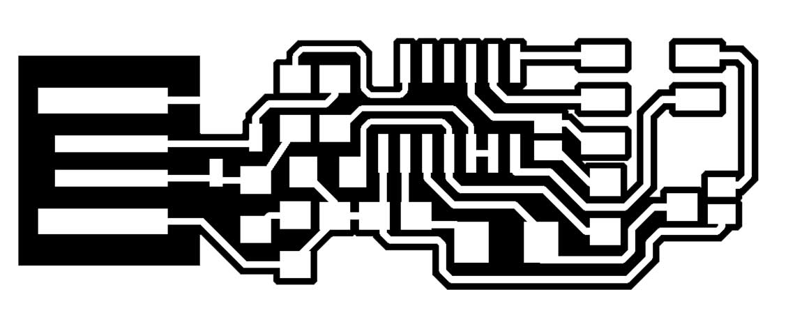
The first thing we had to was to pick a model for the fabrication of our PCB, among the examples given during the week’s lecture.
I am completely new to this, so before I could decide anything, I had to learn more about how a PCB works, how it is designed, more importantly what is the role of each component and finally what could be the advantages of this or that board.
To do so, I looked into all of the pages provided on this week's lecture page, and then I dove back into my Arduino starter kit to remind some of basinc principles that would help me be more confortable with general electronics.
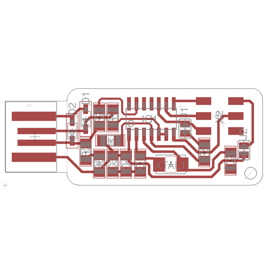
Finally we chose this one, because it already includes USB pins, which means we won’t have to solder the micro USB port.
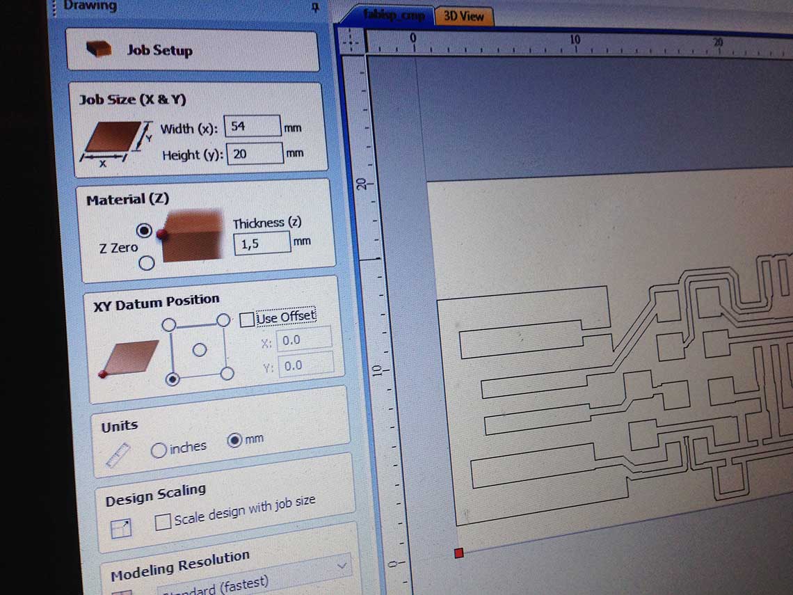
So we used the PNG files for the pocket and the cut.

We converted them into dxf and edited them with V-Carve, which the software that we use to configure that machine.
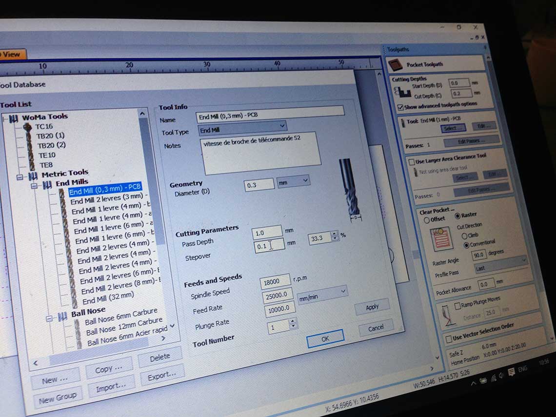
The settings for the pocket are :
| Parameter | Value | Unit |
|---|---|---|
| Speed | 18 000 | r.p.m (round per minute) |
| Feed rate | 25 000 | mm/min |
| Plunge rate | 10 000 | mm/min |
| Cutting depth | 0.2 | mm |
We will be using a 0.3 V bit, because our fablab has not received the 1/64 inch bits they ordered yet.
 Once every thing is set, you save the file on a USB key, load it into the machine and let it work its magic !
2. The PCB fabrication
Because it is a big machine, before we started, we had to make sure the bed sheet was stable and completely flat. For this, we used the vacuum pump included in the machine.
The end mill works pretty much like a laser cutter : you must set the origin point manually moving the bit on x and y axis.
Then once it is done, you must set the z value.
Finally, after you set the speed, you can start the job.
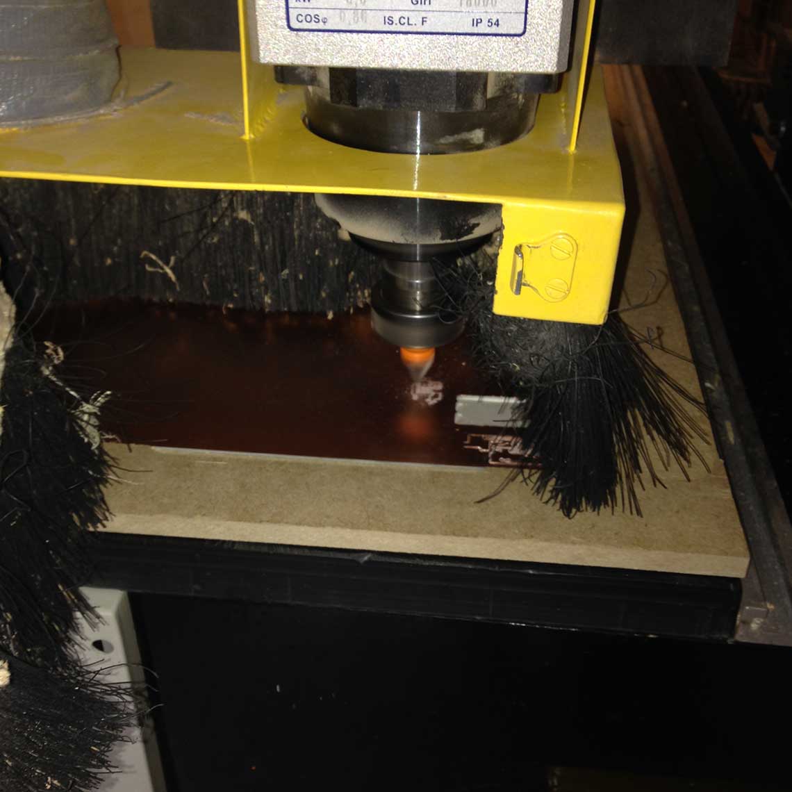 With the settings and material we had, it took about 20 minutes for both pocketing and cutting.
Here is the result before cutting.
With the settings and material we had, it took about 20 minutes for both pocketing and cutting.
Here is the result before cutting.
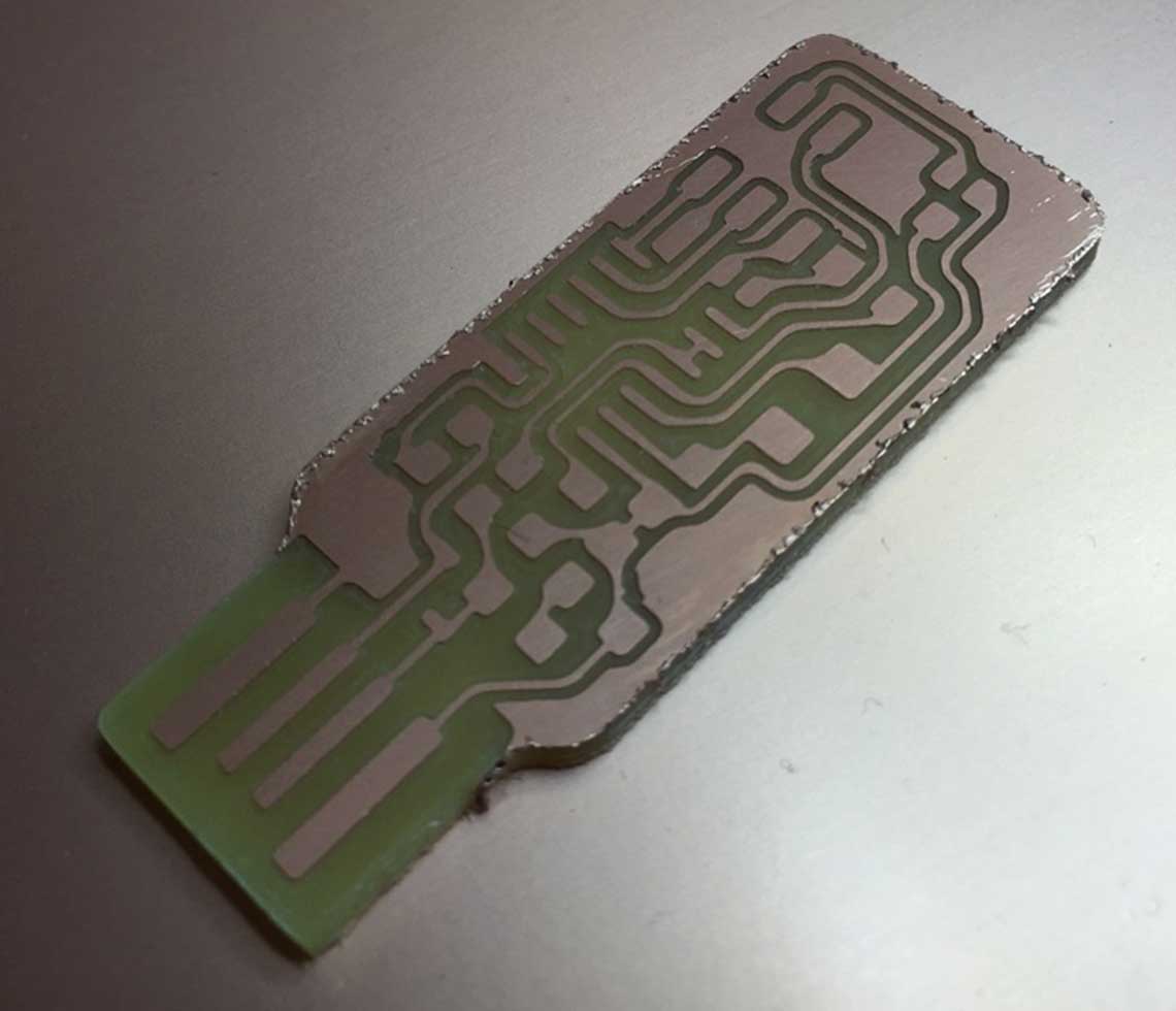
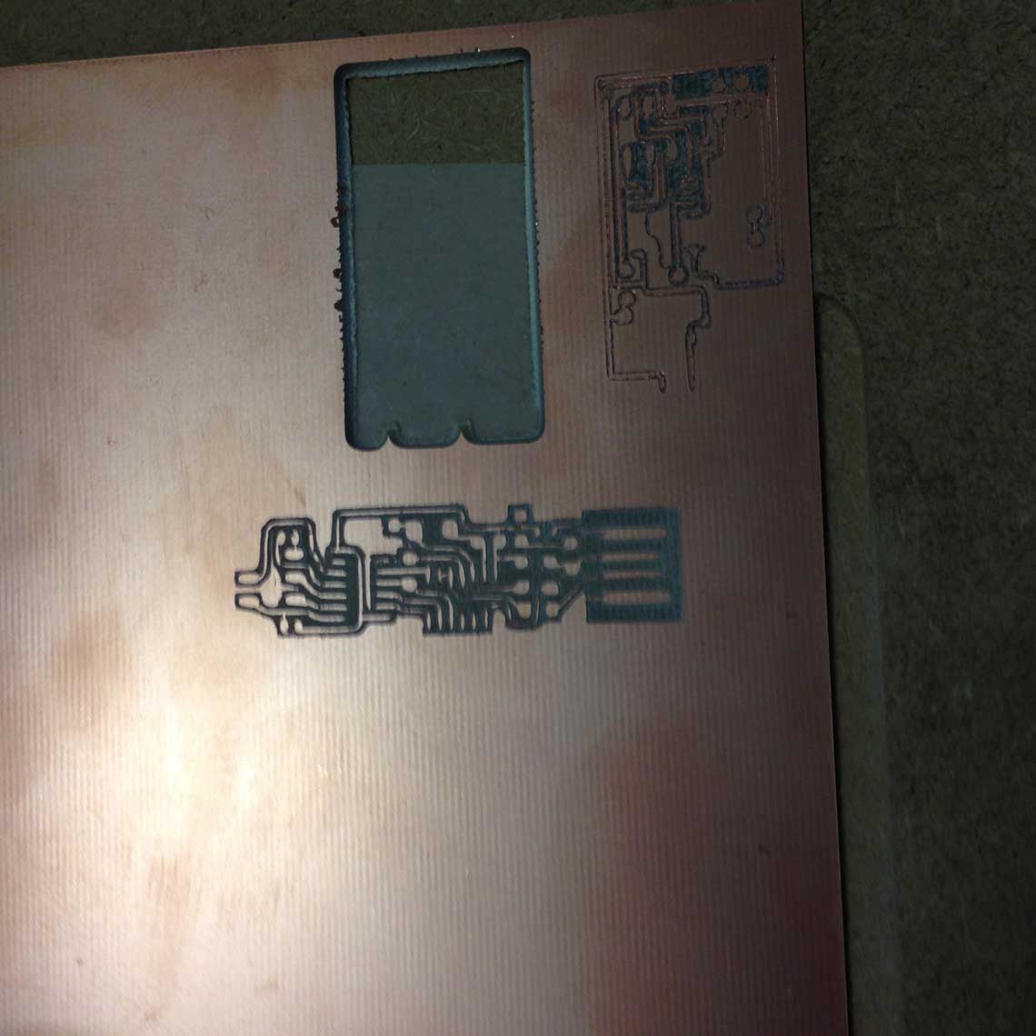 And here is the final result.
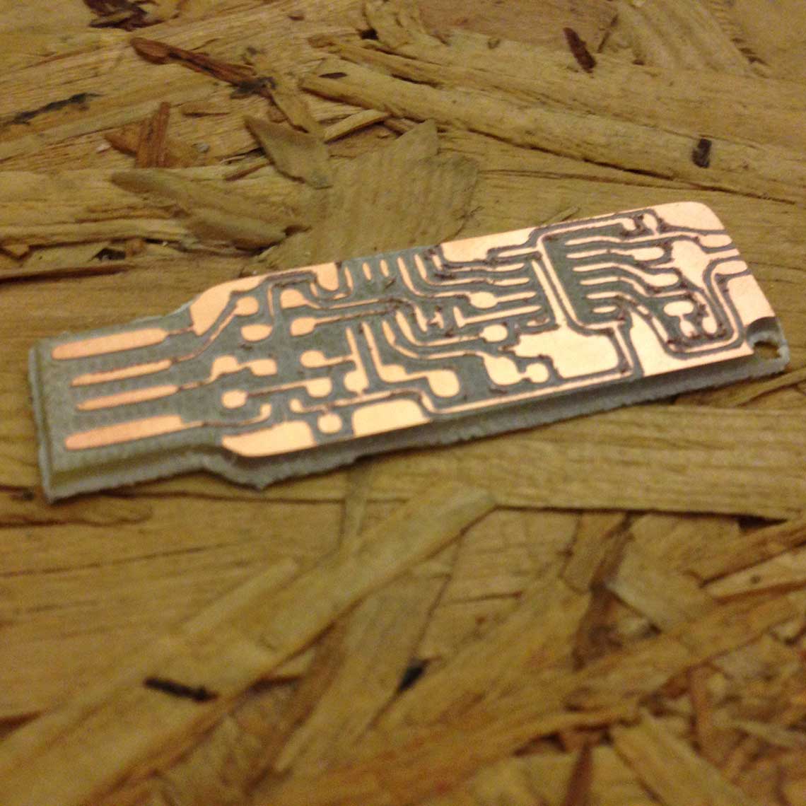 It is not as clean as it would be with a 3x2 end mill like the one witch is recommended, but it seems good enough to be working.
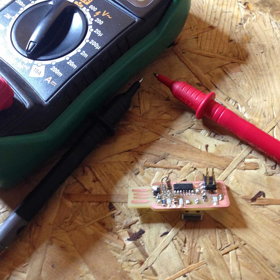
To make sure, we tested the board with a multimeter :
It is not as clean as it would be with a 3x2 end mill like the one witch is recommended, but it seems good enough to be working.
To make sure, we tested the board with a multimeter :
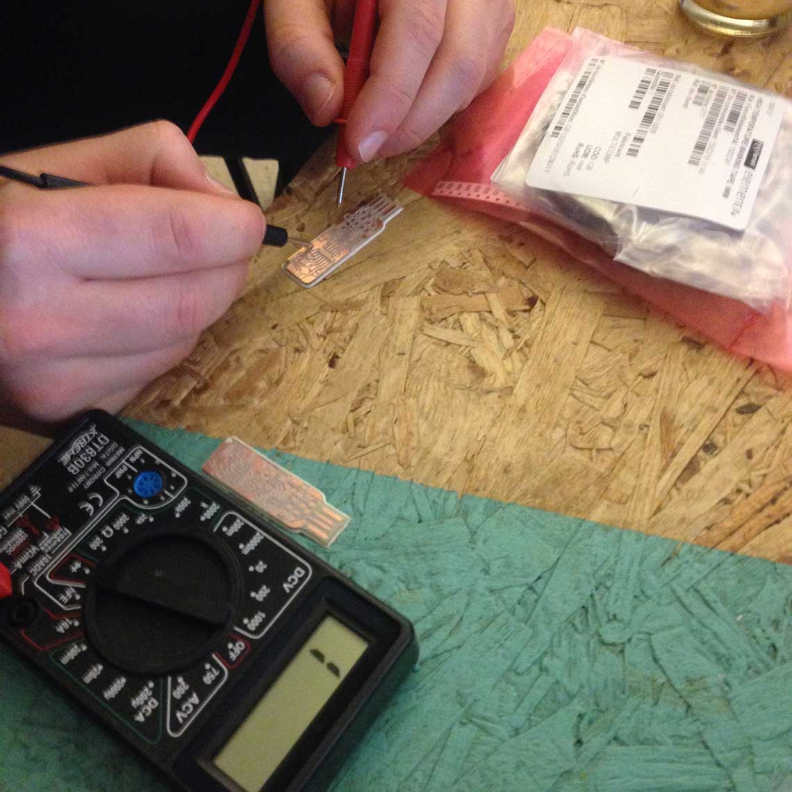 It was OK.
But the problem is we realized that we did not start with the right design for the board. On the FabISPKey page, there is two versions : the normal one and the « lokey » one, which we used. But we don’t have all the components necessary for the lokey, so we had to do it again with the original ISPkey version.
This time instead of doing a pocket, we only do a profile cut so that the just is more precise.
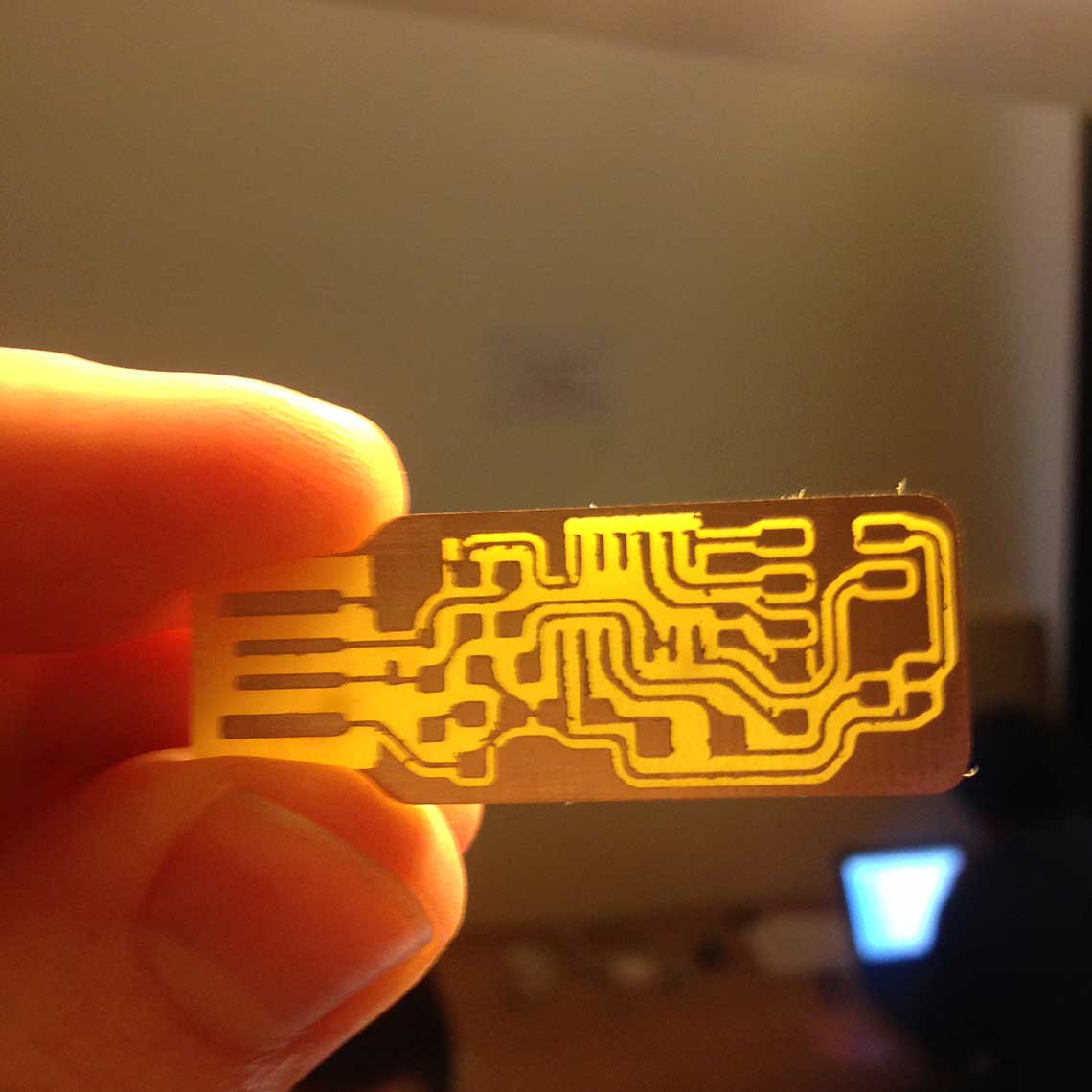
First time we tried the job was much faster (less than 5min) but we realized we made a mistake when converting the files from PNG to pdf and then dxf, which resulted in a difference of scale.
So the ISP was smaller and actually too small :
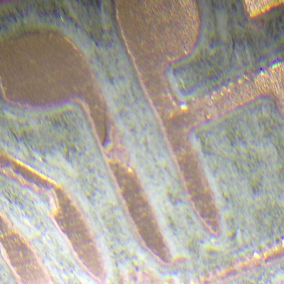
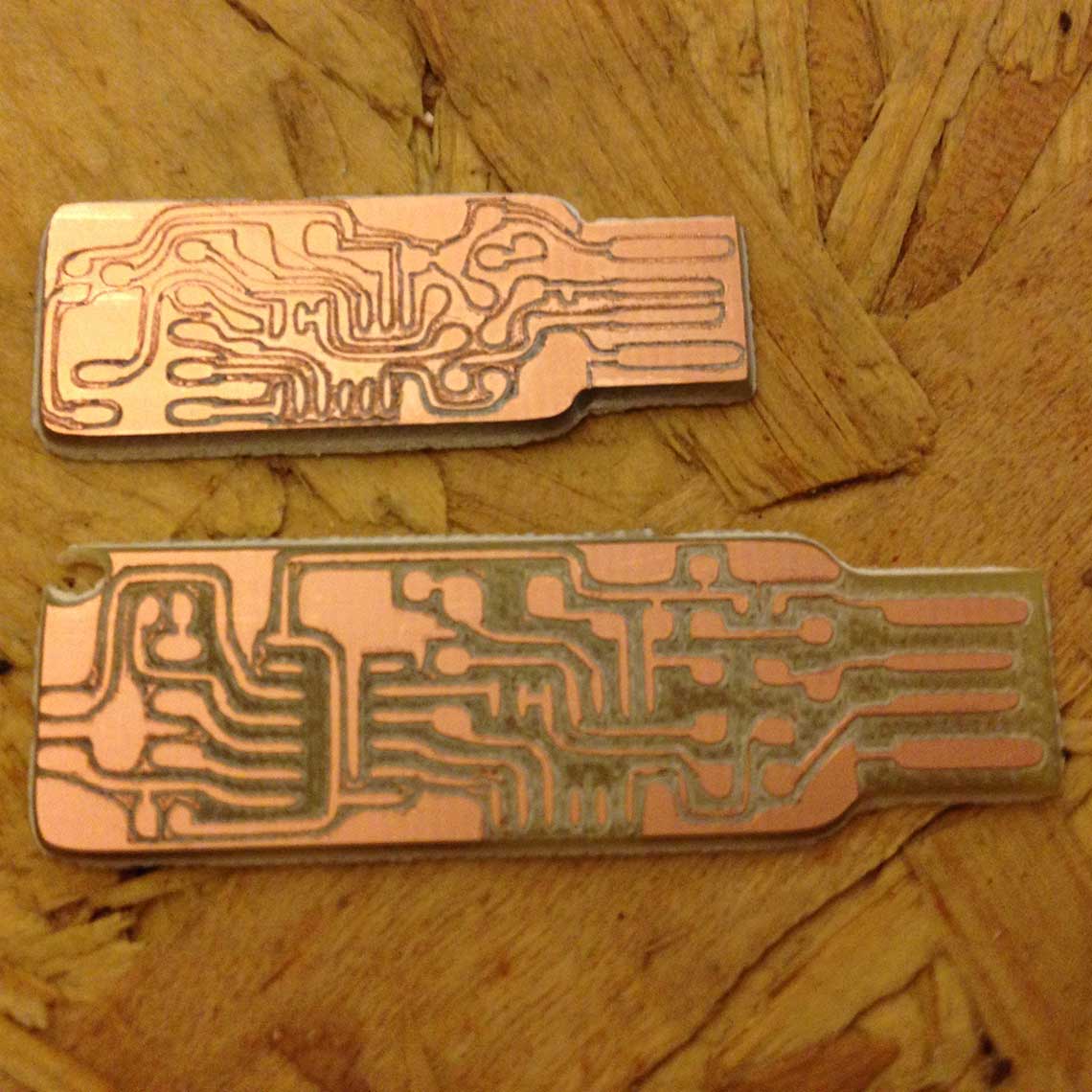 And also the profile was not deep enough. We can see on this photo that the copper is not completely cut.
 So we had to regenerate the file again.
This time, to be sure we had the right file and dimensions, we directly downloaded the Eagle file from Andy Bardagjy’ gitHub, here.
Once it was done, the third attempt was finally successful :
4. Soldering
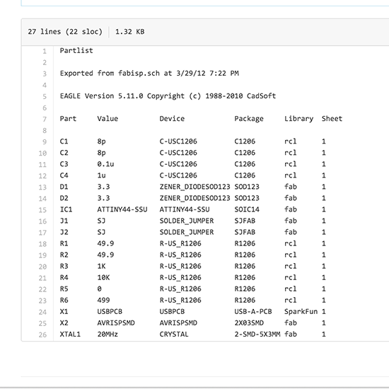
Then came the hardest part : soldering the components on the board. First I had to identify each component and use the schematics provided by Andy Bardagjy to know exactly where to put what :
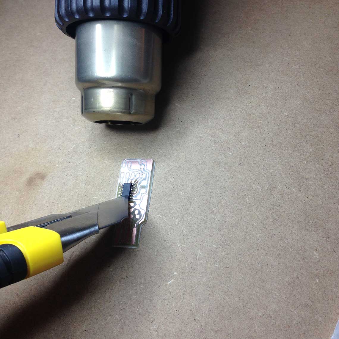
So we began with the AtTiny, using the air blower and the soldering paste. I used some thermic tape to attach the chip to the board on one side, and be able to solder all the feet of the chip to the board on the other side.
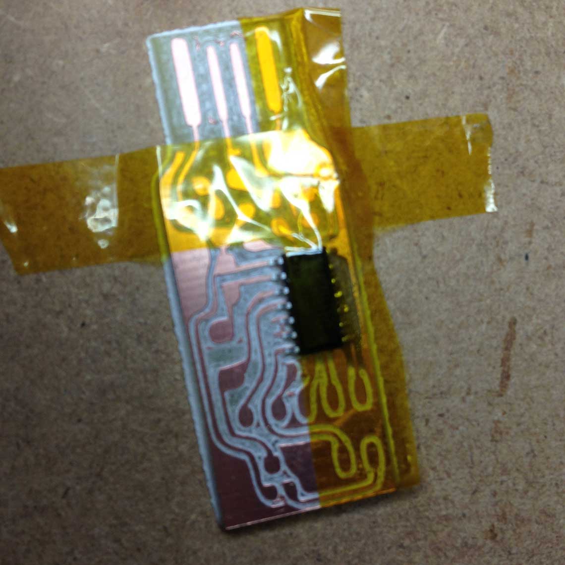
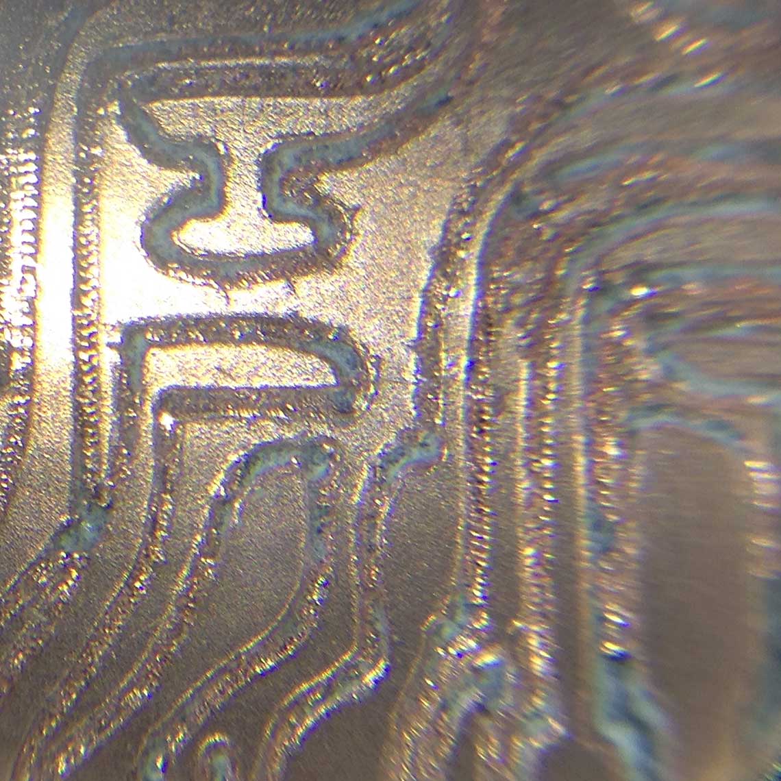
After a few tries it worked although for the moment the result is not so clean.
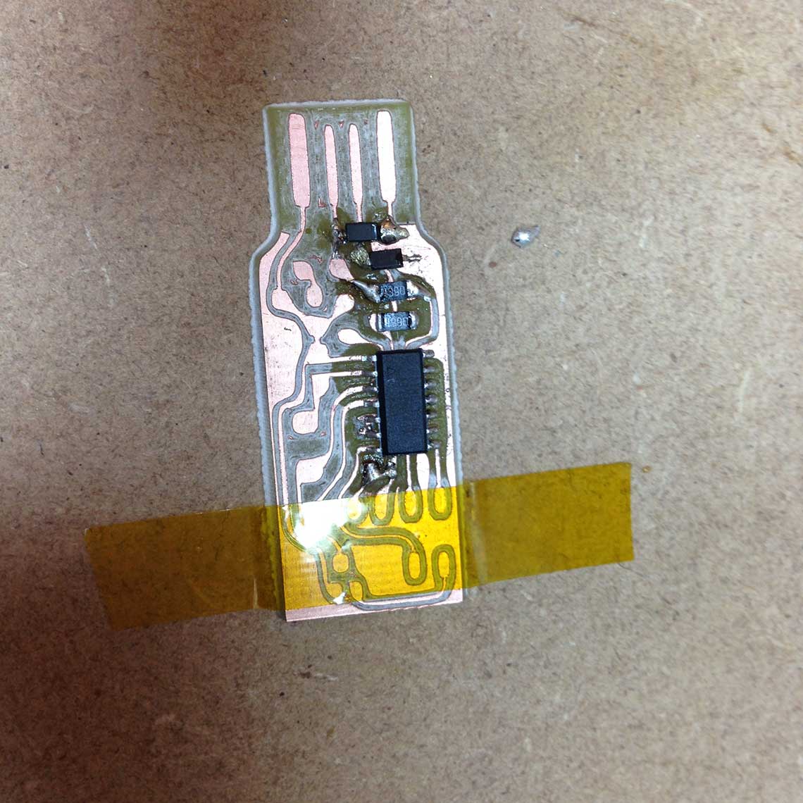 Then I realized I had made a mistake : I did not pay attention and the two diodes were mounted on the wrong side : I had to unsolder both of them en solder them again, which took me a lot of time !
But after that I grew more confident. Because we chose to use the USBKey example, we did not have all the required components. So for the 10kOhms resistance, I chose to use a non-SMD one, which my Fablab had already. I used a small Dremel hand-drill, which is kind of tricky to use, to make the holes in the PCB. By the way I also used it to drill the holes for the crystal. Then I mounted the two components :
My PCB was almost finished, I only had to wait for the last components to be delivered at the Fablab.
Meanwhile, I would try to began to explore the next step which was the programmation of the board.
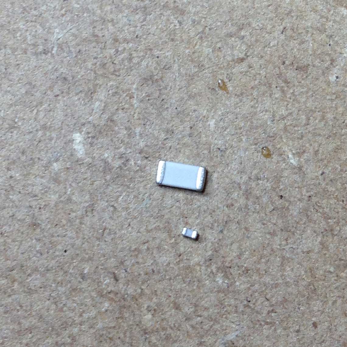
Unfortunately, althought the missing components were delivered on time, some of them (capacitators) were too small to fit to the PCB.
 Also, looking back at my PCB, I realized the solderings were really sloppy.
Some of the copper traces were not well attached which resulted on a unstable current flow, so I
thought it was better do to another PCB from scratch. Given that we had also recieved the new milling bits,
we could mill new boards.
Also, looking back at my PCB, I realized the solderings were really sloppy.
Some of the copper traces were not well attached which resulted on a unstable current flow, so I
thought it was better do to another PCB from scratch. Given that we had also recieved the new milling bits,
we could mill new boards.
That is what we did, this time using those parameters instead :
| Parameter | Value | Unit |
|---|---|---|
| Speed | 18 000 | r.p.m (round per minute) |
| Feed rate | 1000 | mm/min |
| Plunge rate | 100 | mm/min |
| Cutting depth | 0.2 | mm |
This time the bit we used was a 1/64inch one, which is approximatly 0.397mm.
The result was undoubtedly better although the paths were still pretty rough and kind of uneven.
 But this took quite some time and we did not have enough time to mill, solder all
the components and do the programming by the end of the day.
But this took quite some time and we did not have enough time to mill, solder all
the components and do the programming by the end of the day.
So the programming step would be postponed to the next week.
Update - 10th March
I finally found time to pratice my soldering and finish the Fab Isp. Well, it actually took me two tries to finish it. The first version I made was pretty messy and I made the mistake of soldering the crystal too soon, because at that time we did not have recieved the capacitors yet. As a result, it would be almost impossible to solder them afterwards because I would have to go under the crystal... :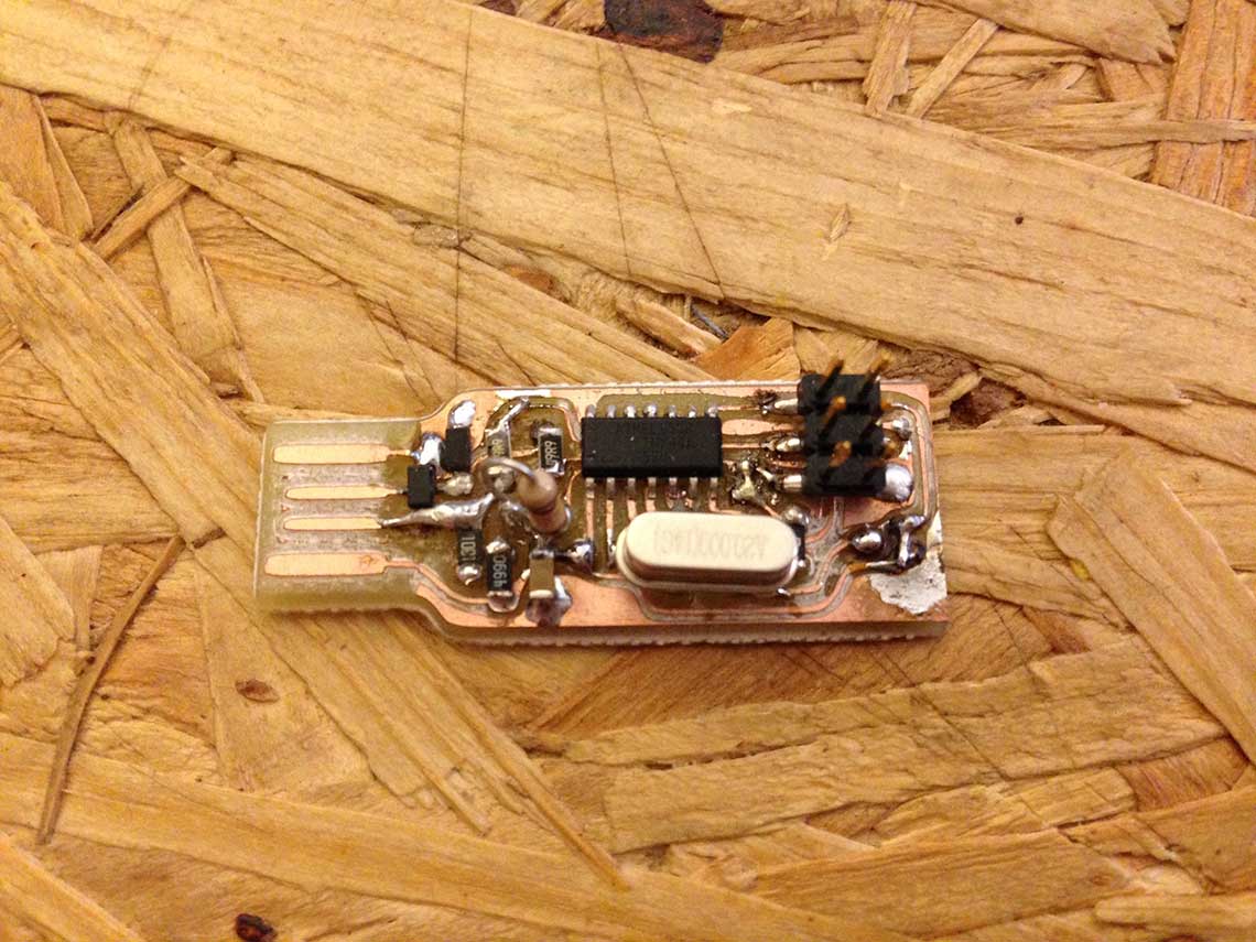 So I decided to redo another PCB from scratch and this time I got a much better result.
For the fabrication, this time we used even slower parameters, putting the advancement rate at onlu 01.m/sec and the the depth at only 0.1mm. Also, to make sure the Z was correct we used a very clever technique shown to us by Saverio that consists in putting a piece of paper between the board and the milling bit, and to slowly put down the bit tenths of mm by tenths of mm until the paper cannot move anymore sideways. We obtained a very clean result !
 Of course it will be even cleaner and much faster to produce when we will have received the right milling machine. I'll talk about that later.
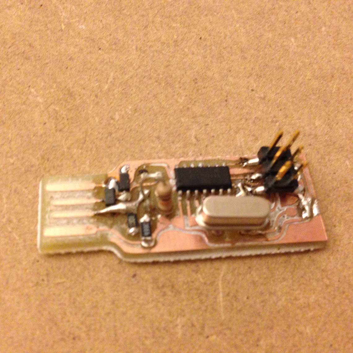
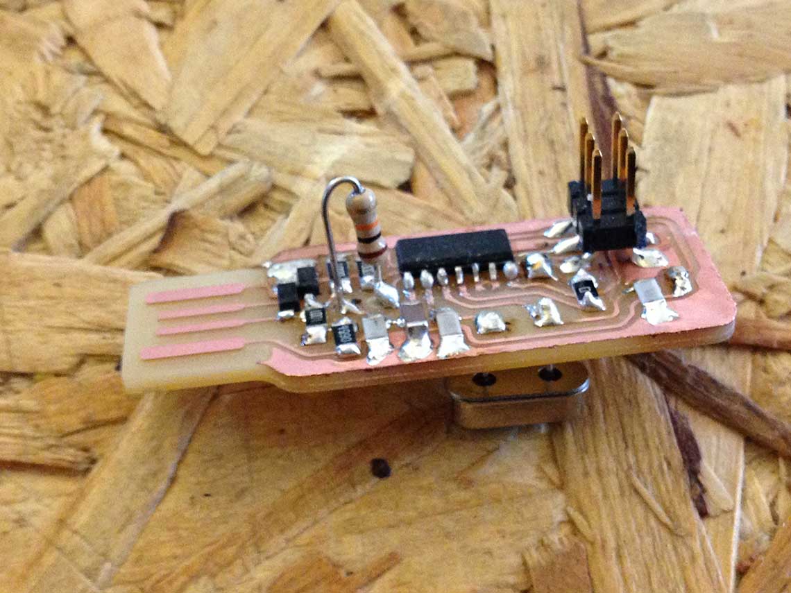
As for the soldering phase, on this version I chose to put the crystal underneath the board as I found it easier to solder this way :
 5. Programming the PCB
First of all I downloaded the firmware.zip package here, then I installed CrossPack which is a development tool for AVR microcontrollers.
Since we did not already have an ISP to use for programming the FabISP, we wanted to use a Arduino UNO. So I followed the Fab Academy tutorial on how to turn an Arduino UNO as an ISP and then use it to program our ISP.
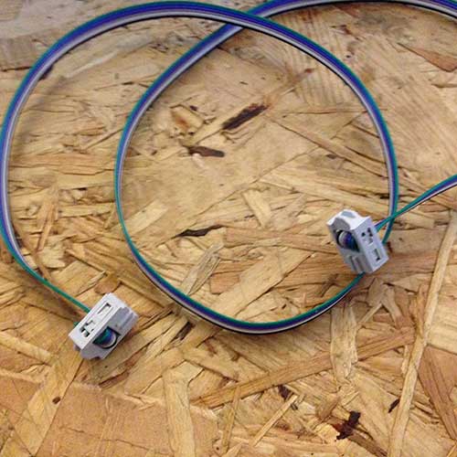
Then I made a 6pin cable to connect the Arduino board to the FabISP :
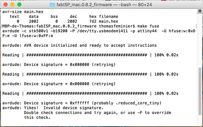
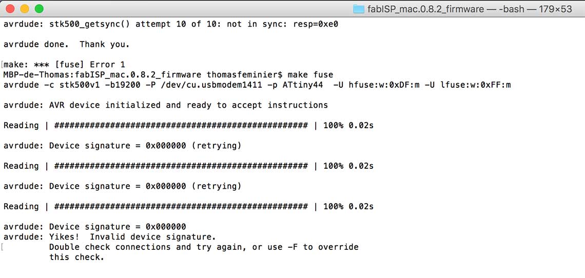
 Once this was done, we had a really hard time during the second phase, when trying to set the fuses so the board will use the external clock : each time we types
 Make fuse we had an error message saying Invalid device signature
. Here is a screenshot of the terminal :
 And here is how the Arduino and FabISP where connected to each other and to the computer :
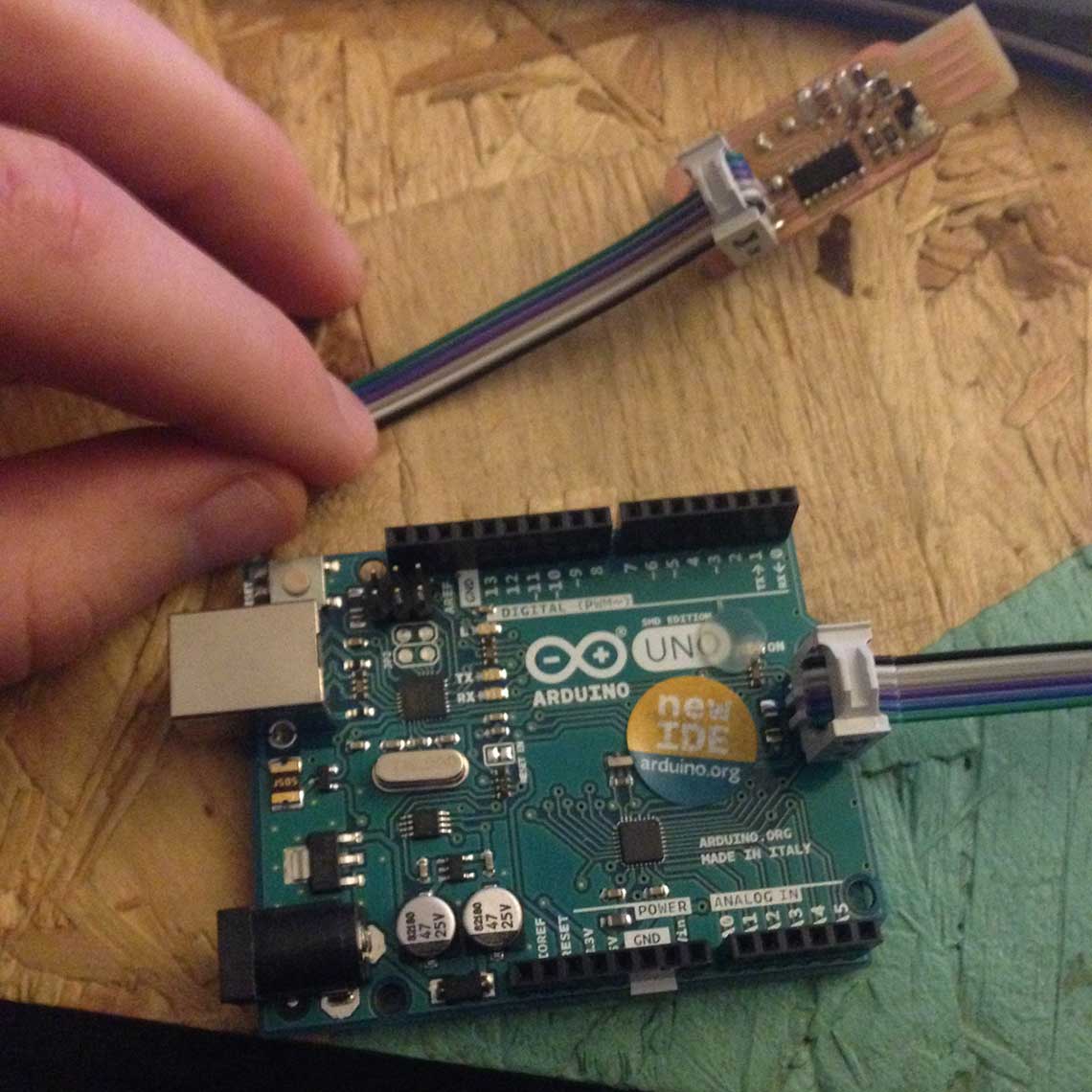 FabISP connected to the Arduino UNO using the jumper cable
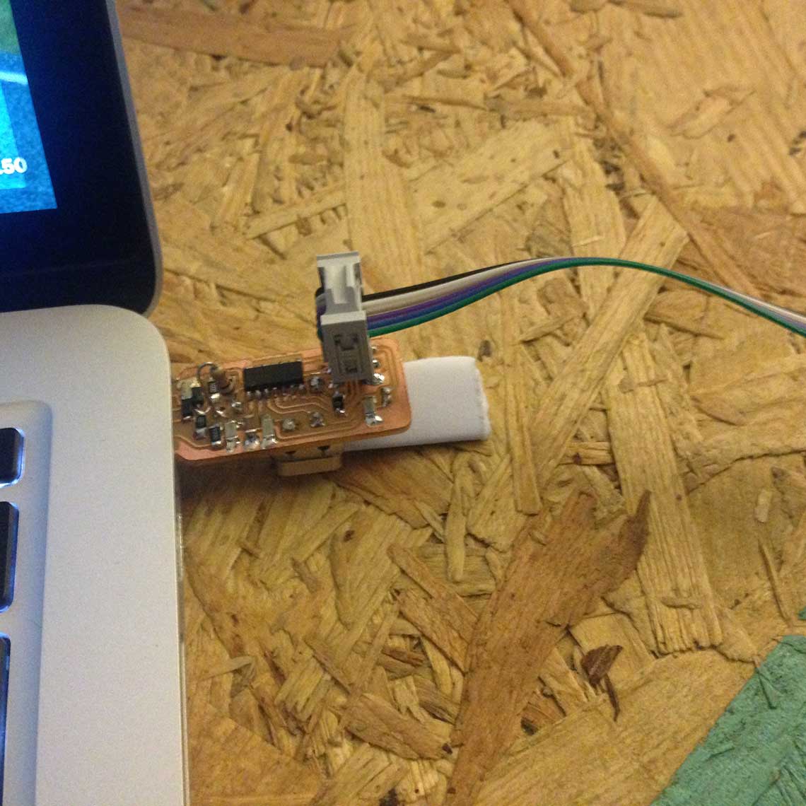 And FabISP connected to the USB port using a folded piece of paper to hold it in place
We tried a lot of different configurations for the connections, tried also on a different computer but it did not work either.
We redid a complete check of all the connections on the board itself to make sure there was no short circuit of mistake in the soldering but everything was ok.
 And it was.
Ultimately, we decided to follow the advices of other students and instructors on the Class alias and we purchased an Atmel ICE Programmer.
It was supposed to be simple to use and I followed the instructions that I found here.
But it did not work either. To be continued...
Update 29 June
I decided to try something else : making a new fabISP, this time using the original version provided on the class' page. I did the one with the resonator.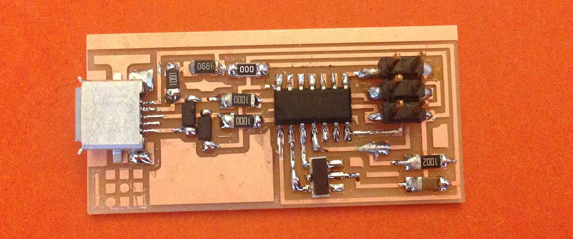 You can find directly the traces here and the dimension here.
Using the same process as before, with an Arduino Uno as an ISP, I tried to program the ISP, putting the following parameters in the makefile :
You can find directly the traces here and the dimension here.
Using the same process as before, with an Arduino Uno as an ISP, I tried to program the ISP, putting the following parameters in the makefile :avrdude -c stk500v1 -b19200 -P /dev/cu.usbmodem1411 -p ATtiny44 -U hfuse:w:0xDF:m -U lfuse:w:0xFF:mBut I still had the same issue : "invalid device signature" :
 Then I decided to try something else : using a programmer instead of the Arduino Uno. The attempt with the Atmel ICE turned out to be unsuccessful but we also had a USB programmer, the "USB ASP" which Roman bought on Amazon.
Here is a picture of this device connected with a jumper cable to the fabISP :
Then I decided to try something else : using a programmer instead of the Arduino Uno. The attempt with the Atmel ICE turned out to be unsuccessful but we also had a USB programmer, the "USB ASP" which Roman bought on Amazon.
Here is a picture of this device connected with a jumper cable to the fabISP :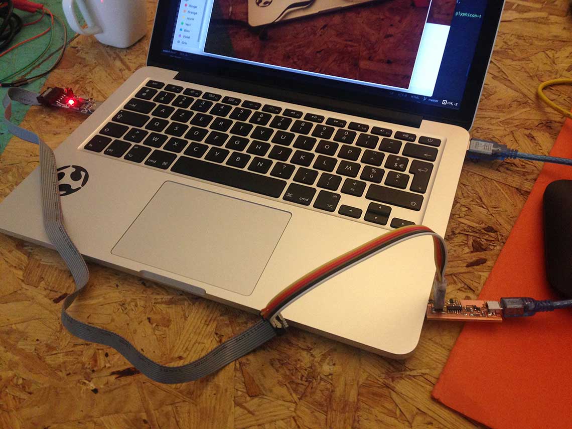 First I changed the makefile according to this new device :
AVRDUDE = avrdude -c usbasp -P usb -p ATtiny44
And tried again with the "make fuse" command. This time it worked right away !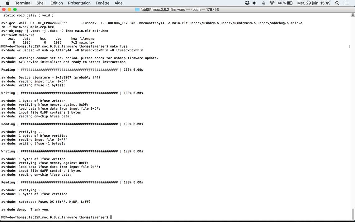 Same thing for the "make program" :
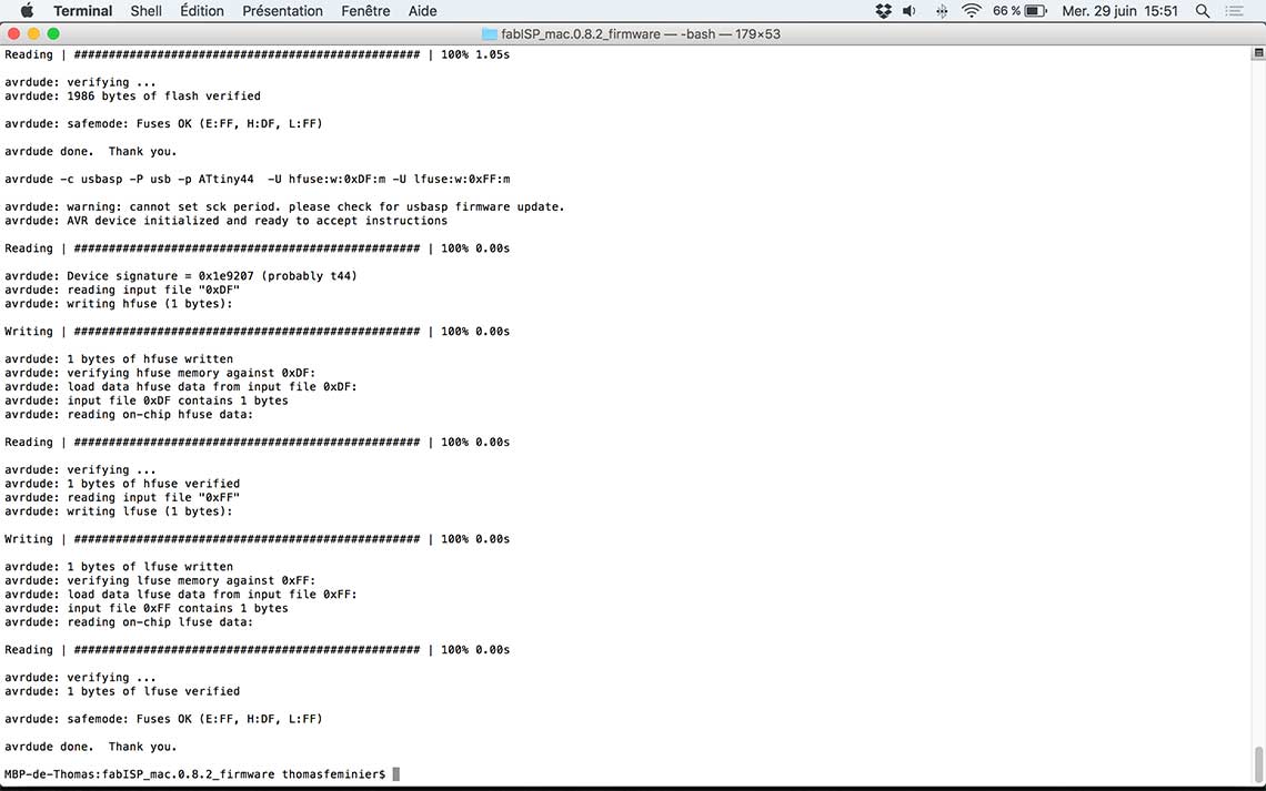 Here is the proof that the ISP was now recognized by my Mac :
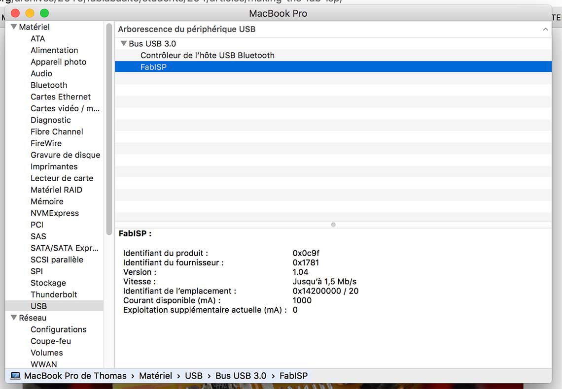 Last but not least, I desoldered the jumpers on the board :
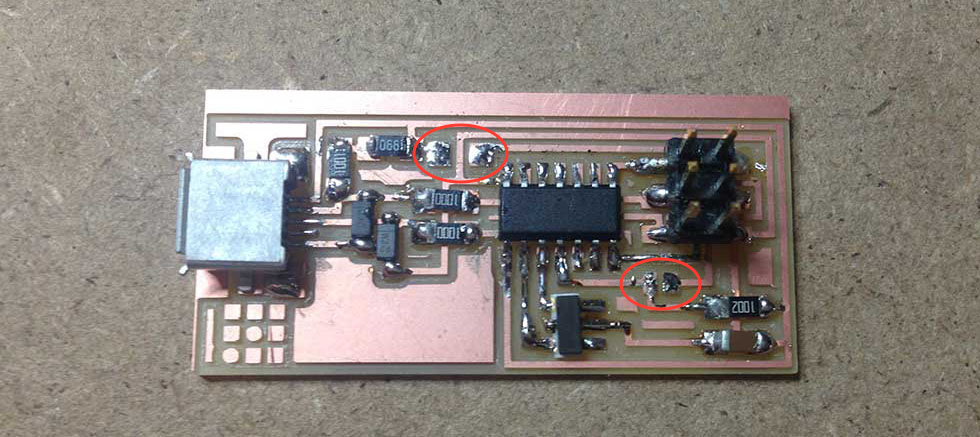 FabISP now ready to program other boards !
Here are the source files used during this assignment.