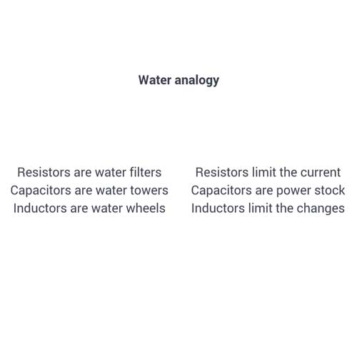
Electronics Design
Week 6's assignment
Specific material and softwares used during this assignment
To begin this week, we did a little workshop during which we reviewed with our two Electronics instructors Fabien and Mathieu the list of the components. They explained to us again what were the particularities of each one. I made some screenshots of the key info of this presentation which was absolutely necessary for me, given that I have very few knowledge of electronics.


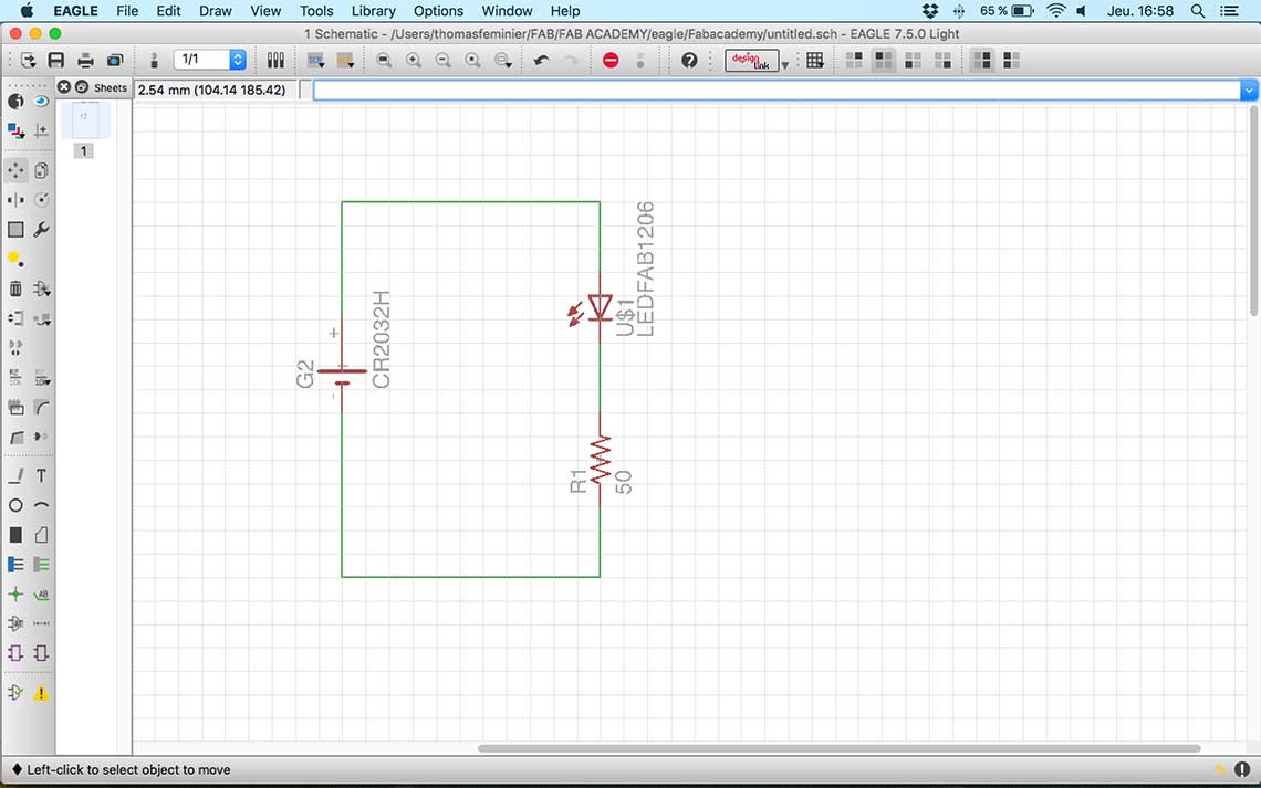
The process is actually more simple than I thought. Once you know which components you want to use and how to connect them to each other, it is quite simple and logic to build your circuit. I learned that it is better not to actually connect all the components together, but to attribute to the wires that you want to connect to each other the same names. Then Eagle will recognize that the wires should be connected even if they don't actually touch each other on the schematics. This technique allows to make much clearer schematics. Here is the first schemactics we made during the exercise :
 To add a component, we must click on the Add button in the toolbar.
 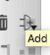 Then a new window appears with the list of all components. To choose a component, we simply have to enter its name in the search bar, using the * symbol to search for every possible occurence. The list on the left represents the libraries, so we will be chosing components in the Fab library when it is possible.
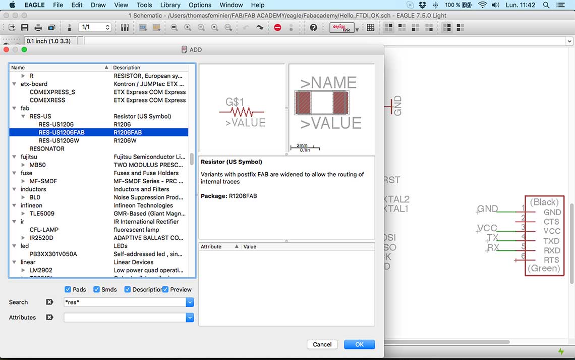 We can see on the right the different visualizations of the component. The first one is its symbol. It is how it will appear on the schematics, the second one is its actual shape and will appear on the board view. It is an accurate representation of the component, and it is important to note that its dimensions are expressed in inches.
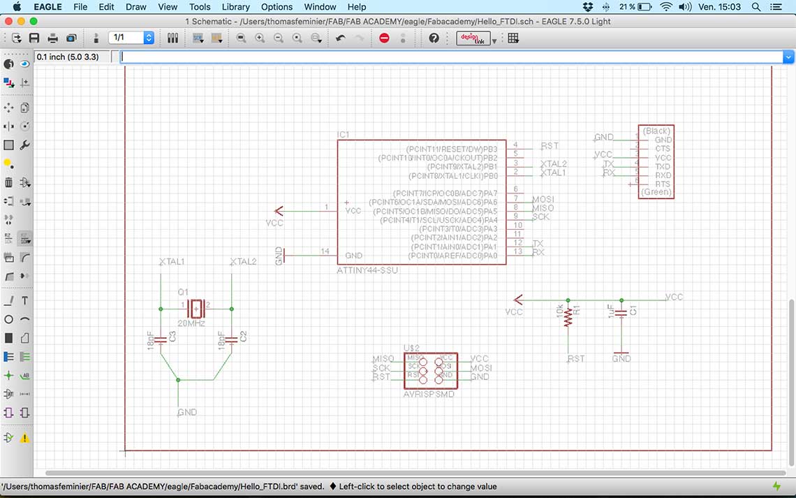
About the connection of the components, on the first schematics we made, the components are directly connected but when you work on a much more complex circuit, it is impossible to do so. This is an example of a more complex schematics htat Fabien showed us :
 Once you have completed your schematics, it is important to always check errors in the circuit. For that, there is the ERC function in Eagle. ERC stands for Electrical Rule Check. This function will point every error on your circuit so it is very important to use every time before passing on the next step, which is the desing of the board.
 Speaking of which, here is how the board looks like :
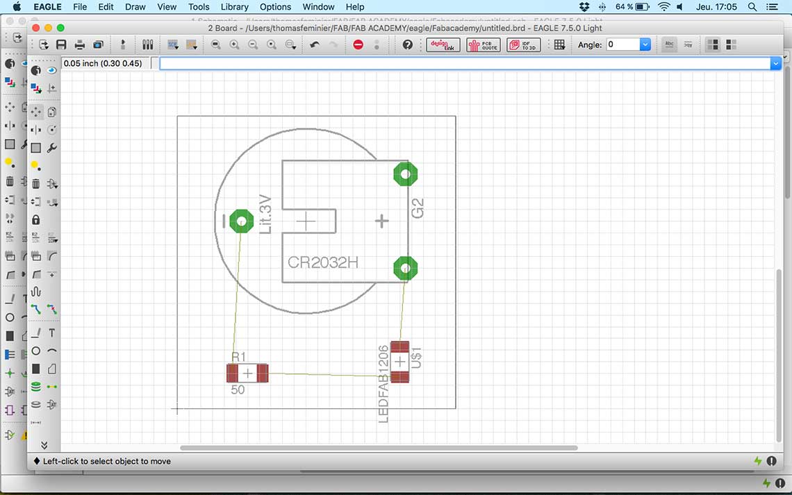 The board view show exatly how the components will be placed on the PCB. When you generate a board for the first time, the components are not placed, so you have to do it manually and carefully chose their orientation. The red wires represent the connections between each component so it helps knowing how they should be oriented.
Then once the components are placed, the next step is to check the design rules before actually drawing the traces. The design rules determine the spacing between the traces, the width of the traces, etc.
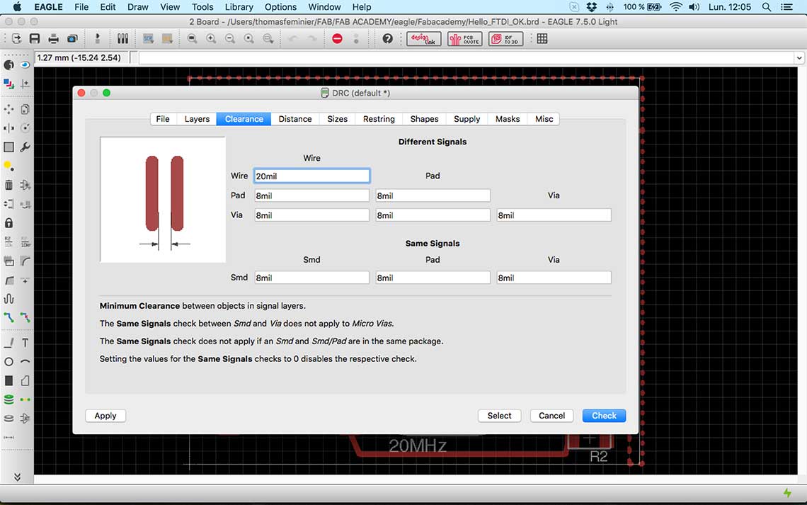 As in the ERC, the DRC function also gives you a list of errors so that you can make sure the board is viable before printing it.
Then you can use the "route" tool to draw the traces.
As in the ERC, the DRC function also gives you a list of errors so that you can make sure the board is viable before printing it.
Then you can use the "route" tool to draw the traces. And there is also a tool that allows to automatically draw the routes instead of doing it by hand. When disigin a complex board, this can be really handy.
 2. Redrawing the echo Hello-World board
Since we learned how to use Eagle, that is what I used to redraw the circuit. I would later try other softwares. First I made a list of the components, then added them on my schematics and connected them together.
2. Redrawing the echo Hello-World board
Since we learned how to use Eagle, that is what I used to redraw the circuit. I would later try other softwares. First I made a list of the components, then added them on my schematics and connected them together.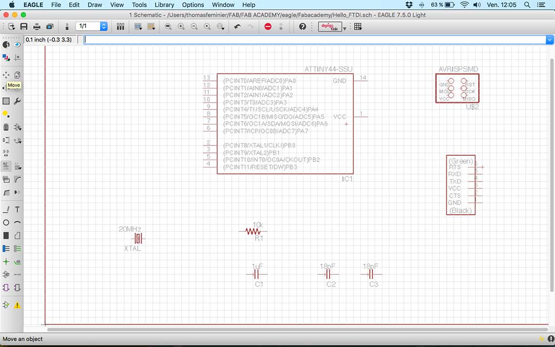
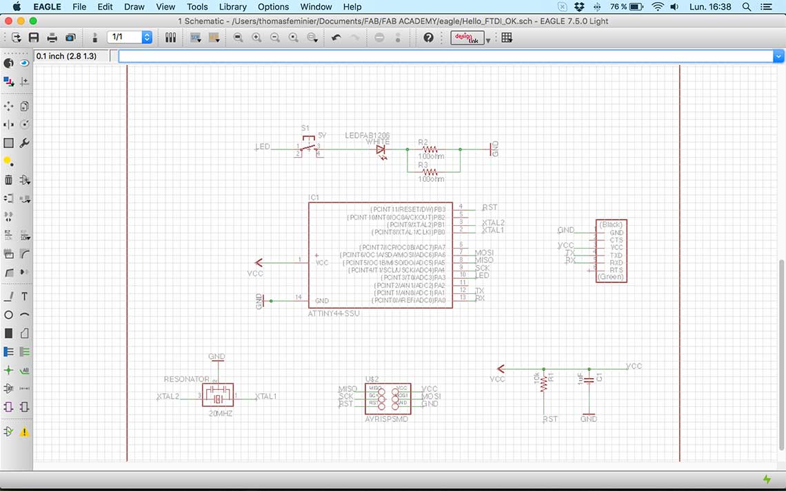
The difference with the original board on my design is that we did not have the right resonator so I had to use a regular Crystal and two capacitors. Then I added the LED and button, along with its resistors. I used the Ohm law to calculate the needed value of the resistor : The voltage of the ATtiny is 5V and according to ist data sheet, the LED we use has a 20mA intensity and a maximum 4V voltage. So the equation is 1/0.02=50ohm. This means I will have to use a 50ohm resistor. Unfortunately we only have 100ohms. To know on which pin of the ATtiny44 I had to connect the LED, I consulted its data sheet and saw that the PA3 pin would be fine.
I had to redraw my schematics when I found out that, finaly, we could use a resonator, so here is the final design :
 And then I generated my board :
 Finding the right routes for the traces took me quite some time, even with the autorouter but it finally worked :
 And I just added some text to identify my board and some external trace using the "rastnest" function.
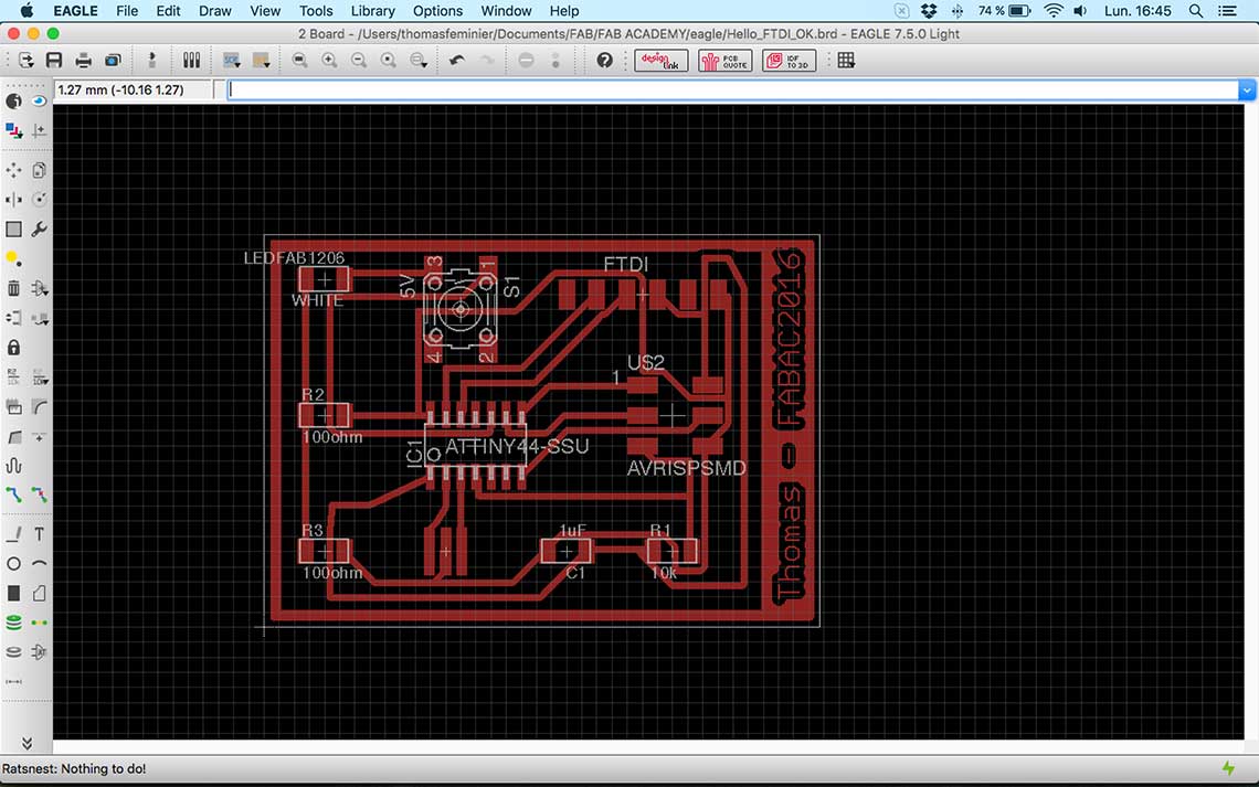 3. Making the board
With Eagle I generated the black and white .png file for the board :
3. Making the board
With Eagle I generated the black and white .png file for the board : Then I vectorized it in
 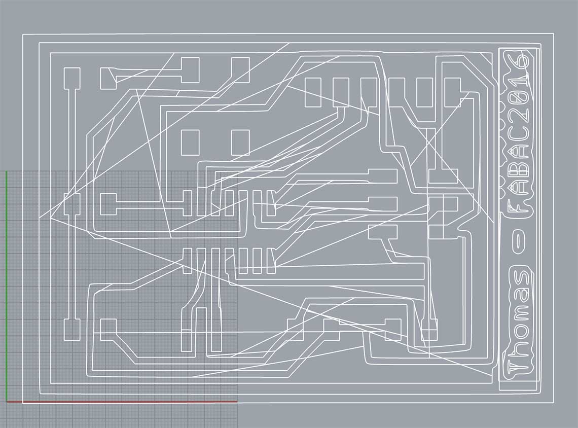 This was due to an error in the vecto file, so I did it again in Inkscape and changed the exporting parameters.
Meanwhile I had recieved some feedback on my design from our Electronics instructor Matthieu, who adivised me to modify some of the traces that where maybe too close to each other, as shown in blue on the following image. The yellow marks are suggestions of better traces :
This was due to an error in the vecto file, so I did it again in Inkscape and changed the exporting parameters.
Meanwhile I had recieved some feedback on my design from our Electronics instructor Matthieu, who adivised me to modify some of the traces that where maybe too close to each other, as shown in blue on the following image. The yellow marks are suggestions of better traces :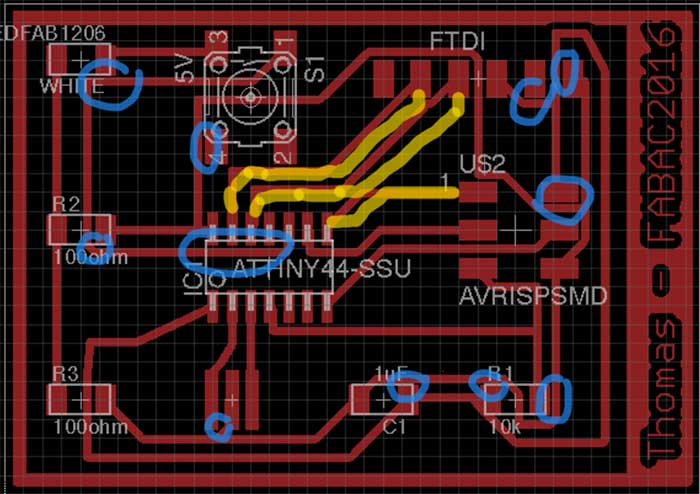 He also said that the font that I used was probably too thin to hold on the board. So I optimzed the traces in Inkscape too. The final result, before importation in V-Carve :
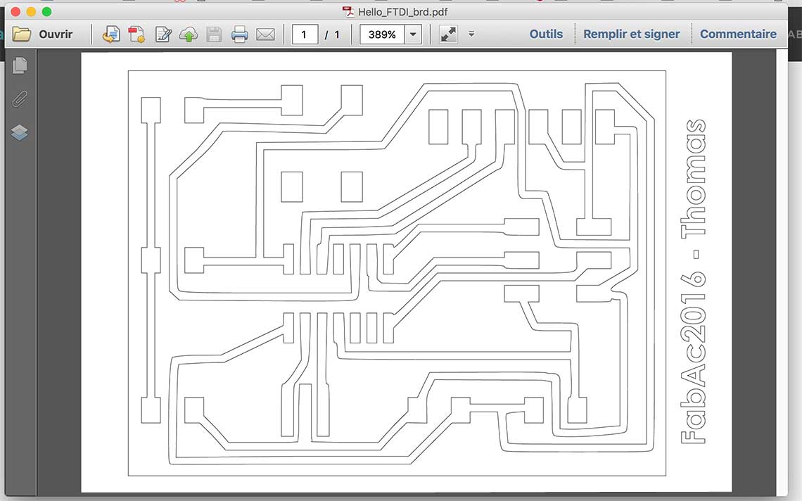 I had to abort the first milling attempt because the traces where a little too thin and there was way too much empty space :
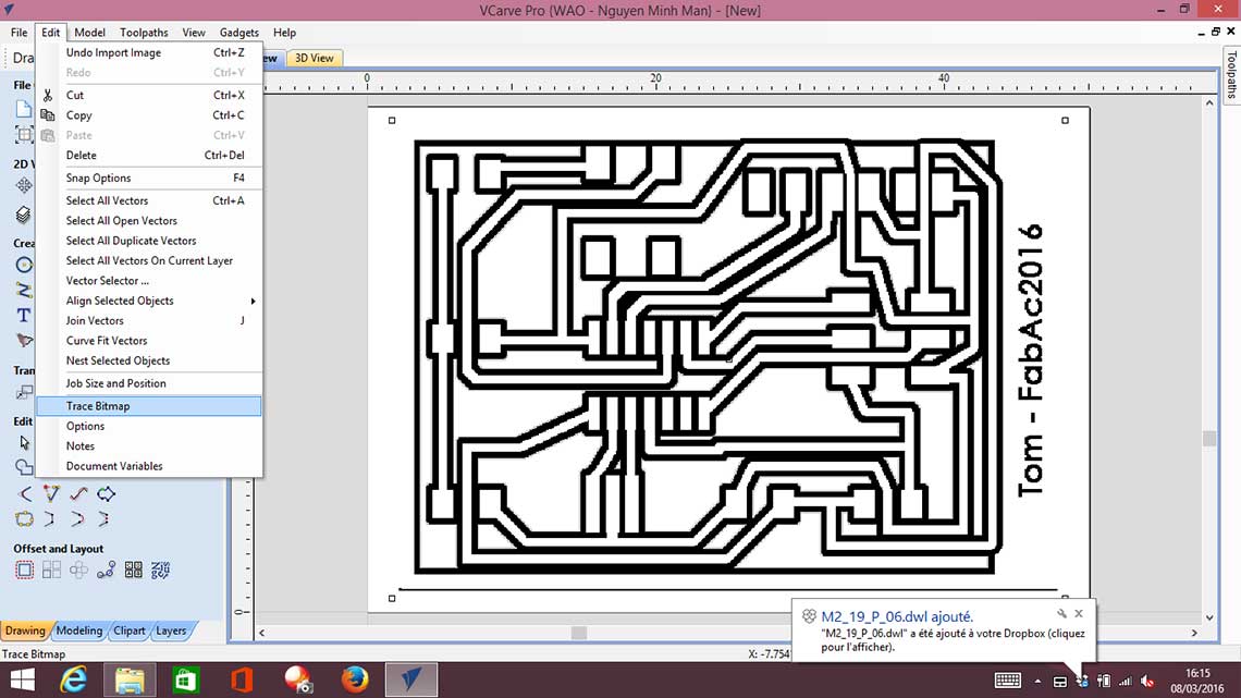
 So I redid the board in Photoshop this time, using the expand function for the traces. This way there would be less copper to cut away and it would be much faster.
By the way, I aslo cleaned some of the traces that I found too uneven or distorted. This time I generated a PNG that I imported in V-Carve. Then I used the "Trace bitmap" function in the Edit menu : this, amazingly, creates a much more accurate vector trace than in Illustrator or Inkscape so it is a really good trick to use.
 Then I was ready to do another attempt. This time it worked just fine and took less than an hour to mill.
Here is the final result :
Then I was ready to do another attempt. This time it worked just fine and took less than an hour to mill.
Here is the final result :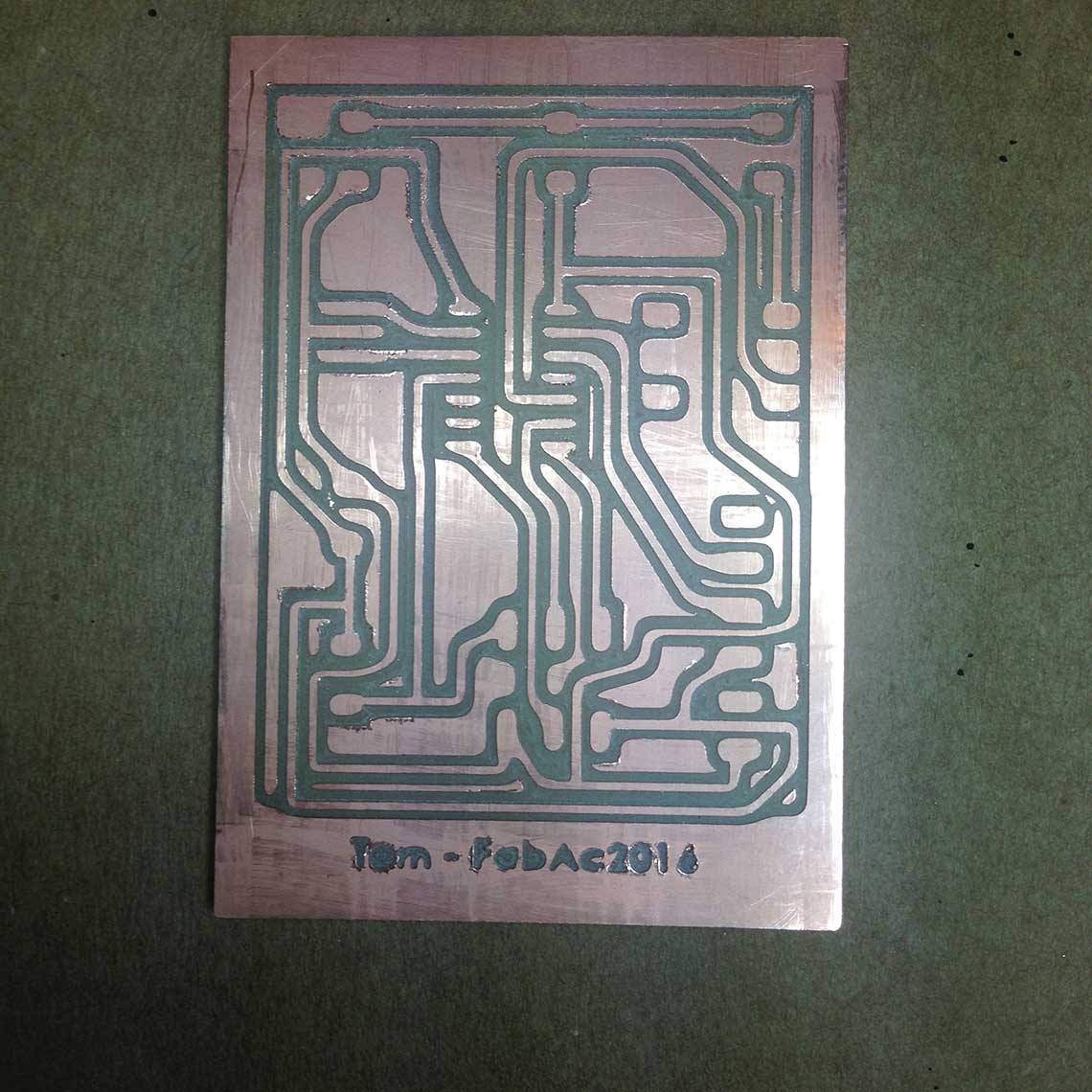 Now, the soldering session could begin ! This time it was quite fast, it only took me like 45mins to complete it all.
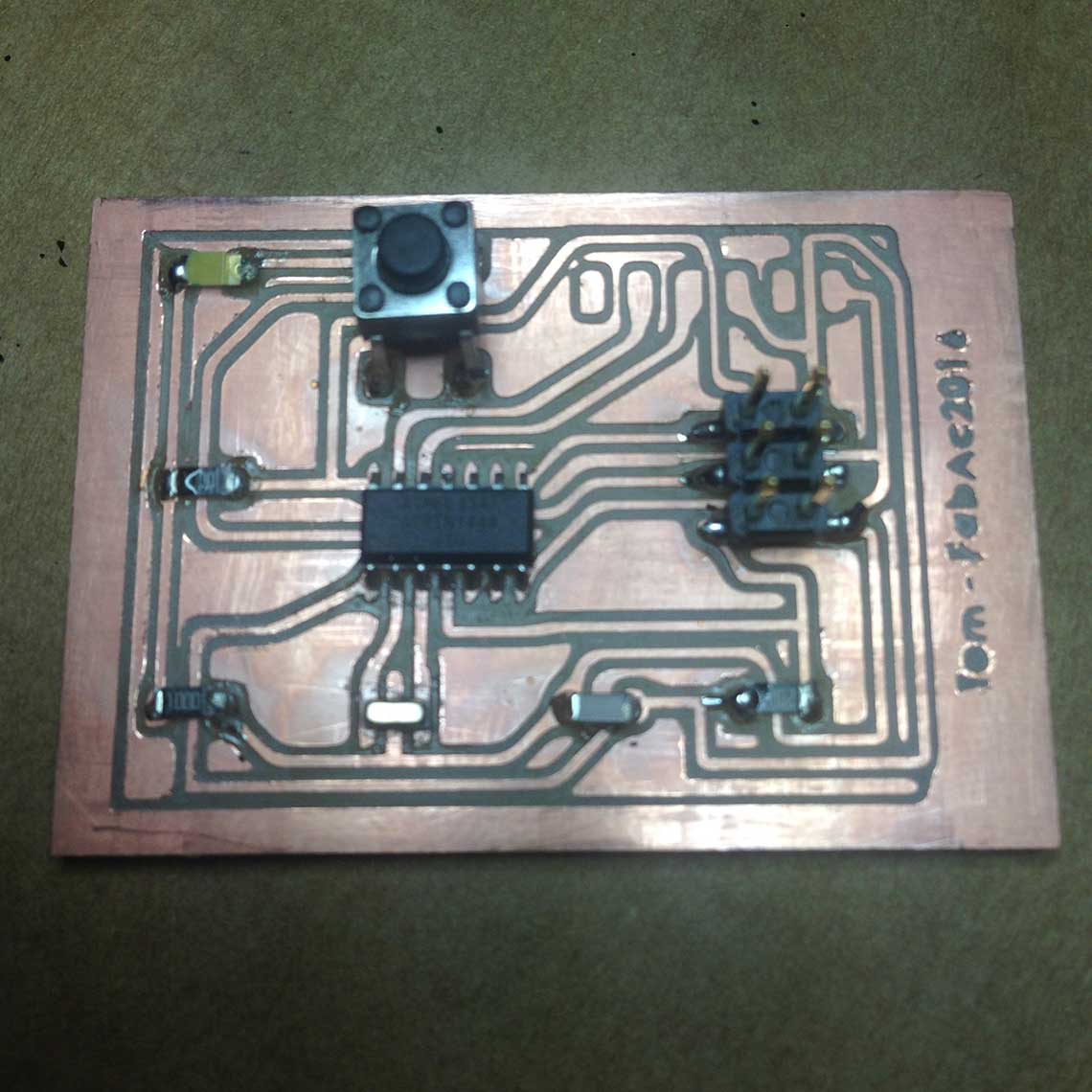
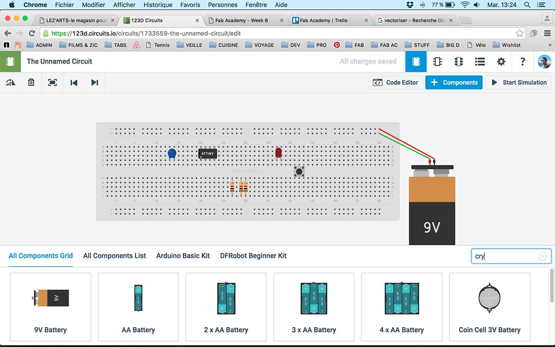
For the extra credit, which was about trying to simulate our circuit, I tried to use 123D circuit but I realized it only allows simulation with Arduino components.
 So I looked for other solutions. There is a plugin for Eagle, called FSpice Simulation : http://www.cadsoftusa.com/eagle-pcb-design-software/partner-products/simulation/
But it is only available for Windows or Linux, and I am a Mac user...
So I looked for other solutions. There is a plugin for Eagle, called FSpice Simulation : http://www.cadsoftusa.com/eagle-pcb-design-software/partner-products/simulation/
But it is only available for Windows or Linux, and I am a Mac user...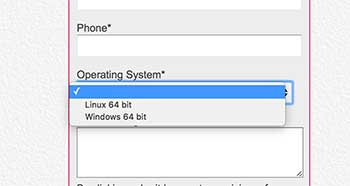 I ran out of time for this week so I'll be looking into this later.