Final Project
Step 4 : Prototyping
In this section I will present the different steps I went through for prototyping my Smart Clock.Outter structure
Choice of the material
I began by looking for the best type of wood I could use to build my clock. I have two criterias on which I will base my choice : the visual aspect and the density.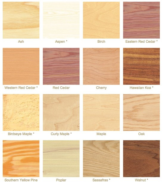 The first one is purely a matter of aesthetics, and on this field I prefer pale types of wood, like pine, birch or beech for example. The second one, on the other hand is really important for my project : I want to cut the wood so thin that it will become translucid.
For that I will need a hardwood rather than a softone (if it is too soft it will break too easily when cut thin) and I will also need a variety with as fine grains as possible and as few knots as possible too.
The first one is purely a matter of aesthetics, and on this field I prefer pale types of wood, like pine, birch or beech for example. The second one, on the other hand is really important for my project : I want to cut the wood so thin that it will become translucid.
For that I will need a hardwood rather than a softone (if it is too soft it will break too easily when cut thin) and I will also need a variety with as fine grains as possible and as few knots as possible too.According to my research on the Internet, it seems like Brich wood would be the best choice.
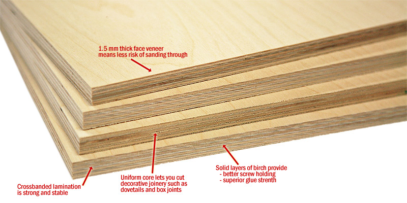
Also, it is quite obvious that I should choose birch plywood rather than raw birch, because birch plywood is among the strongest and dimensionally most stable plywoods. Also it relatively cheap and I since it is very commonly used in FabLabs, I will be able to find leftovers pretty easily to make some tests !
 I must also say that I discussed with the creators of Lunii, a story-tellinng box for kids, who first made prototypes at Woma using wood, and they also advised me to use birch plywood. You can see how this prototype looked like here, and this is their website (not in english sorry).
First tests
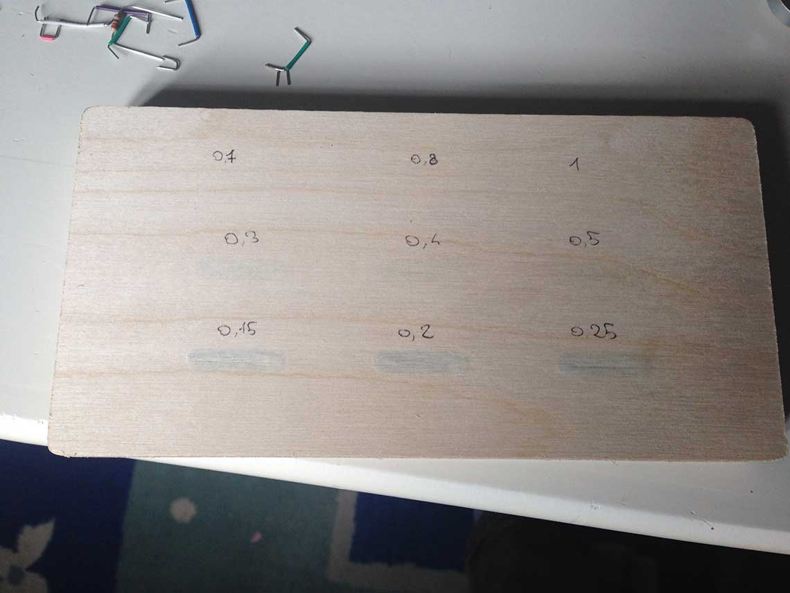
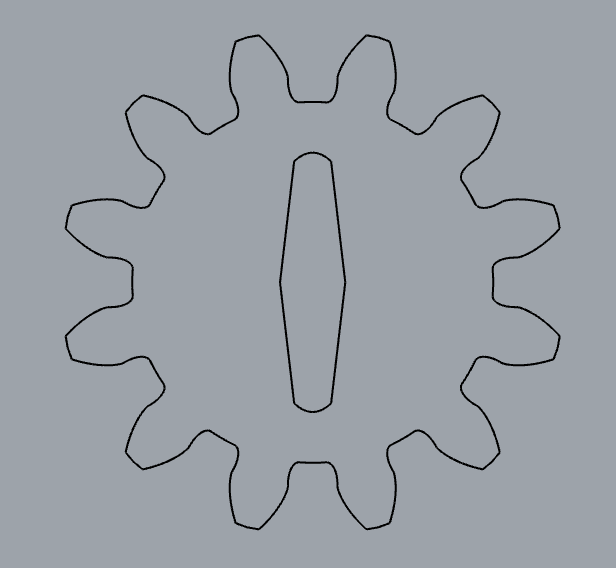
Once I had chosen the material I wanted to use, I could make some tests. I found some 18m: plywood at the lab and I prepared a small cut trial file and a toolpath in V-Carve with different depths of cut to test the limits of thickness I could reach as well as the level of transparency, the question being of course : how thin can I make my plywood board before it breaks ?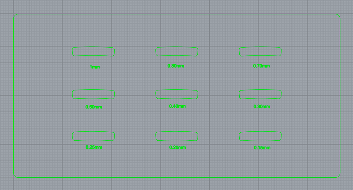 The shapes you see on this image are the ones I want to use to display the hours on the clock. Maybe I will have to change them ultimately according to the results of the tests...
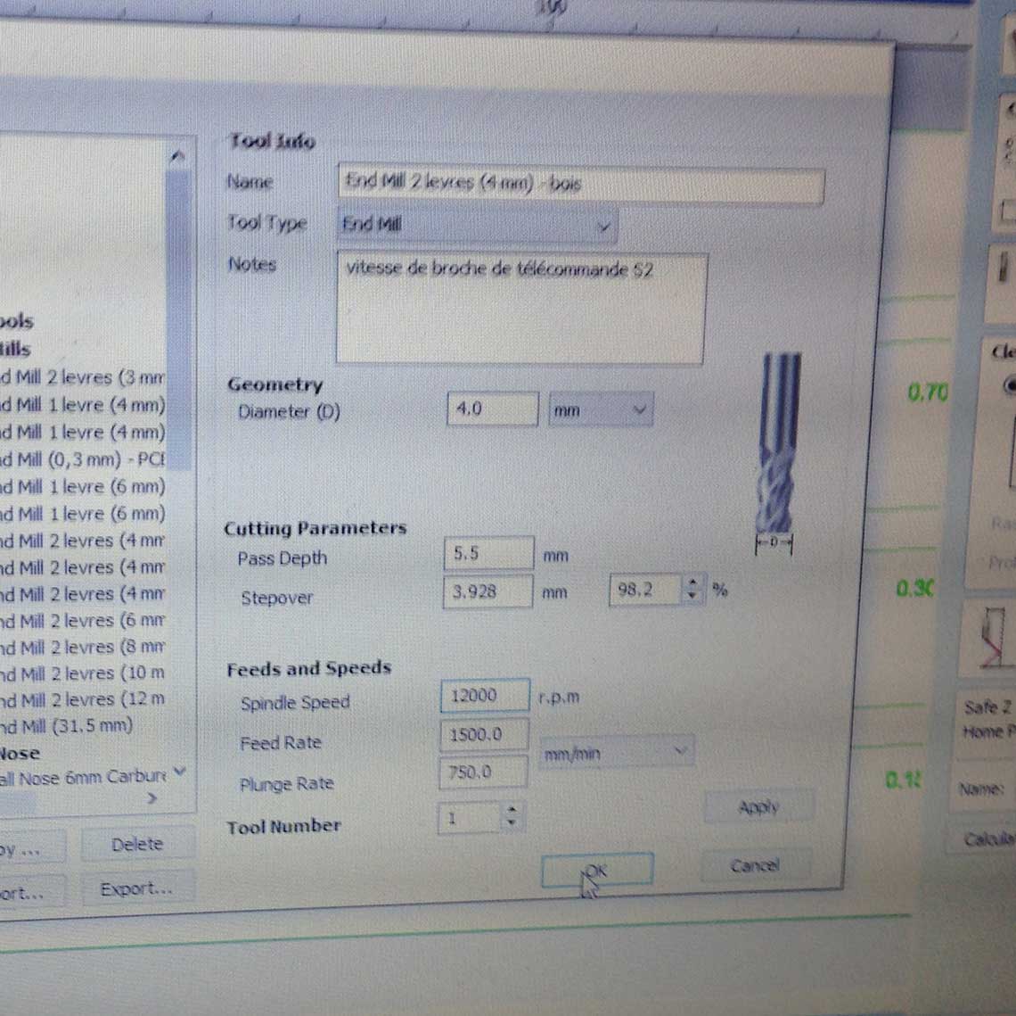
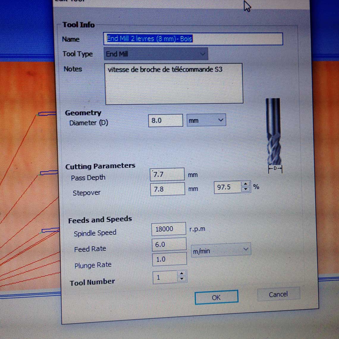
For those tests I used a 4mm end mill for the pockets, and a 8mm one for the profile cut. The settings are reproduced bellow :
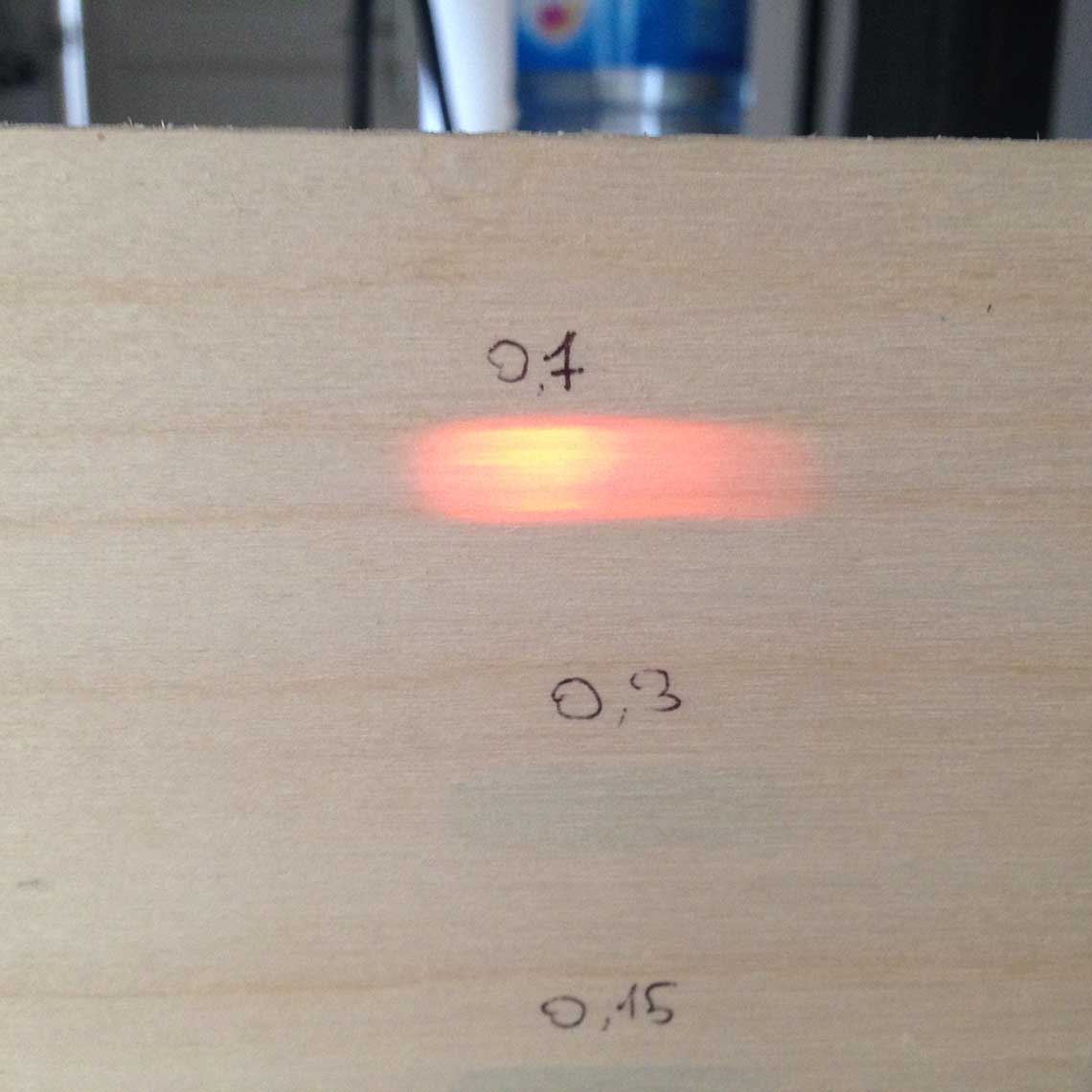
Anyway, here is the result of this test :
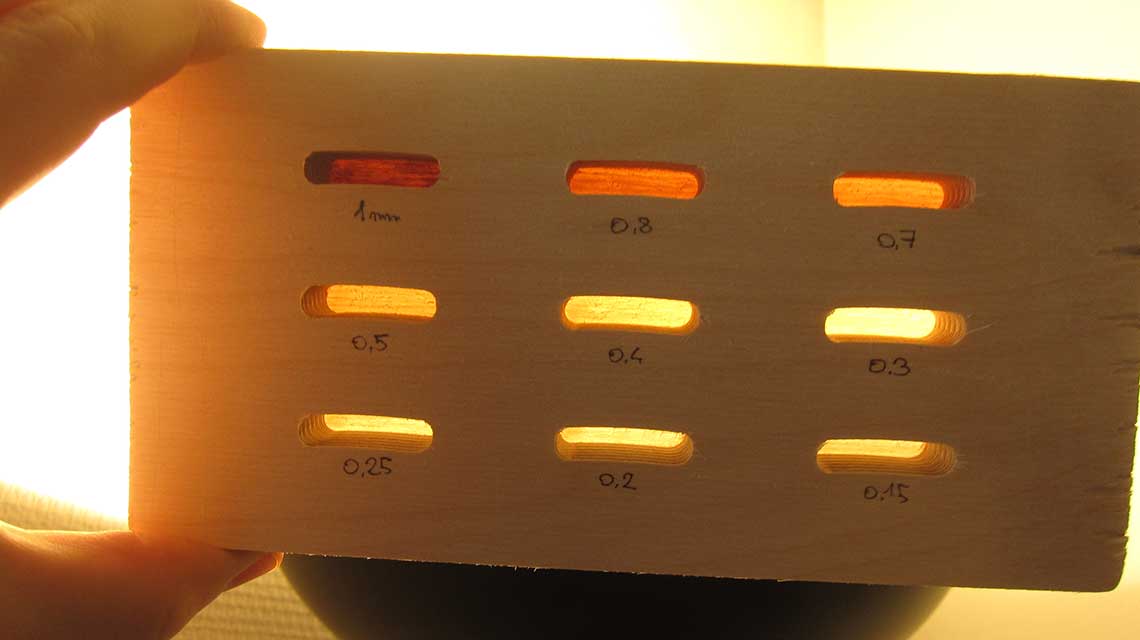 Very neat, very clean and I must admit it did not expect as much ! A few conclusions to this :
- It looks like the "safe zone" is somewhere between 0.7 and 0.5mm - With a higher thickness, it is too thick to see clearly - With a lower thickness, the wood really becomes to be too fragile and also to translucid ! My goal is to be able to see thought it only when it is backlit. When it is not, my wish is that it looks like normal wood !
 Having said that, the next step was to test with LEDs. I tested with an RBG LED, trying to reproduce the colors I used in my design : blue for the hours, orange for the minutes.
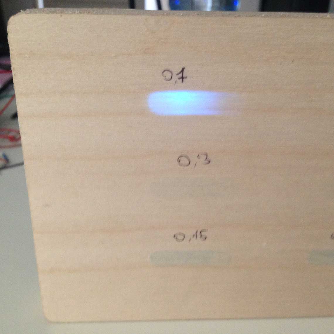
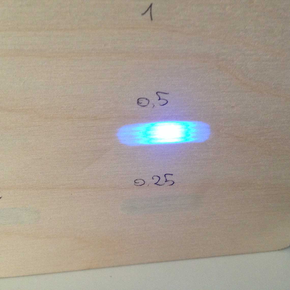
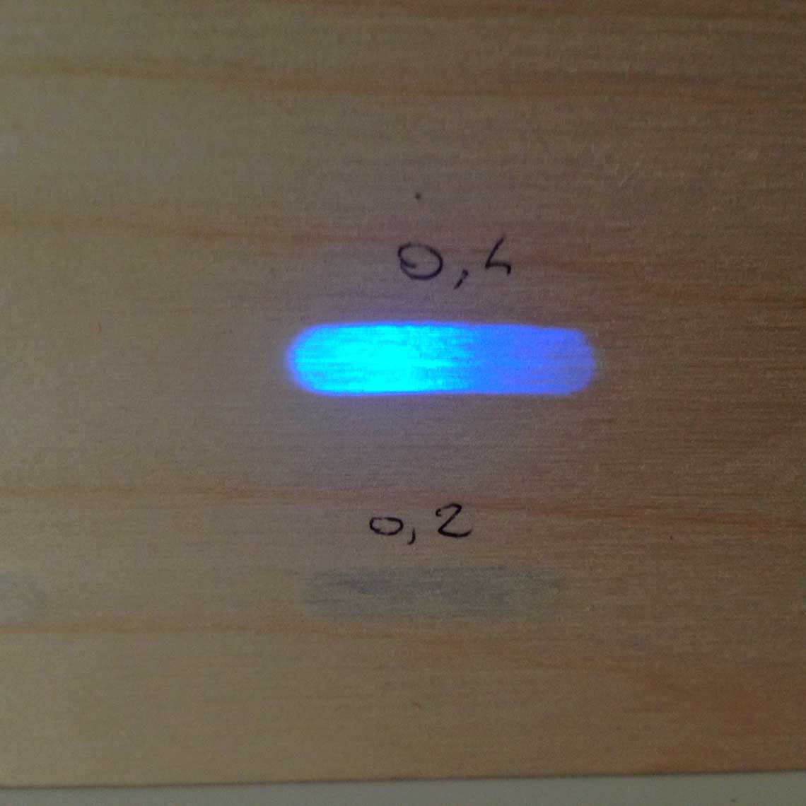
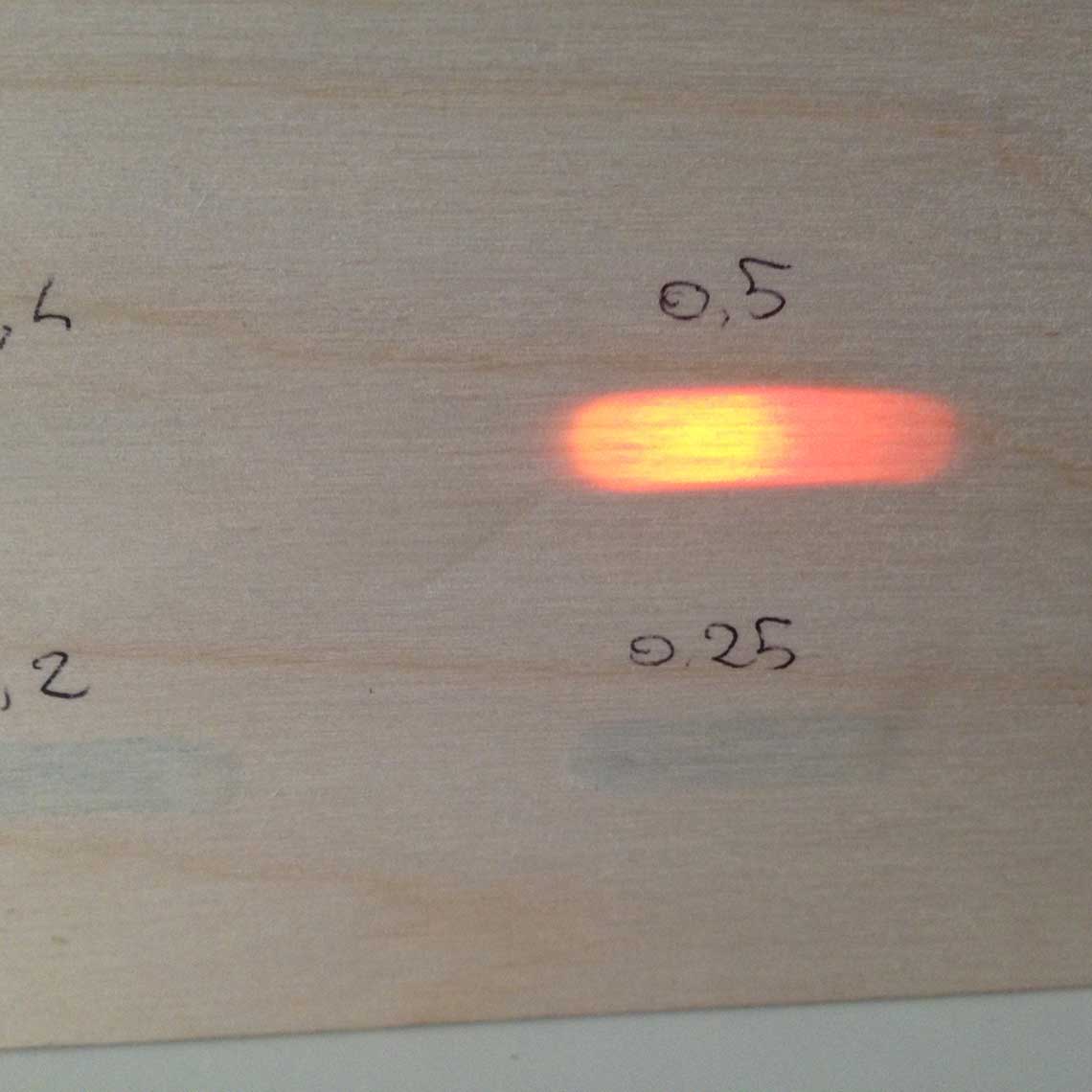
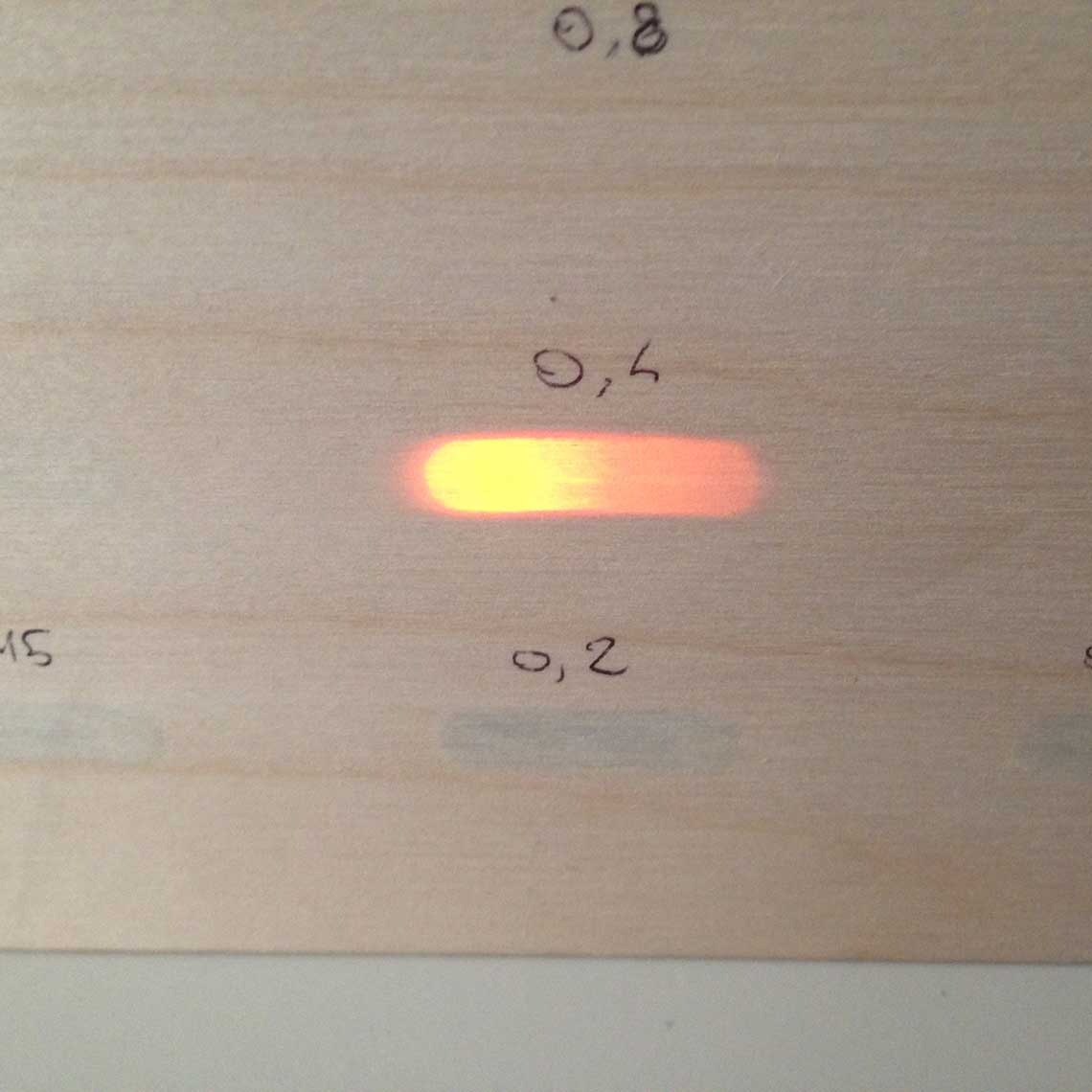
Still, looking at these pictures, it is clear that 0.7 is too thick to have a good effect. There is no big difference between 0.5 and 0.4 so the best choice at this point would be 0.5, to have a good brightness/strengh ratio.
The next phase will be to do the same test with a charlieplexed set of LEDs : they loose brightness when Charlieplexed so this is important to test that even then, they will be bright enough to be seen through the wood.
Then I will test bigger pockets to see how the wood reacts...
Inner structure
The minutes' mechanism
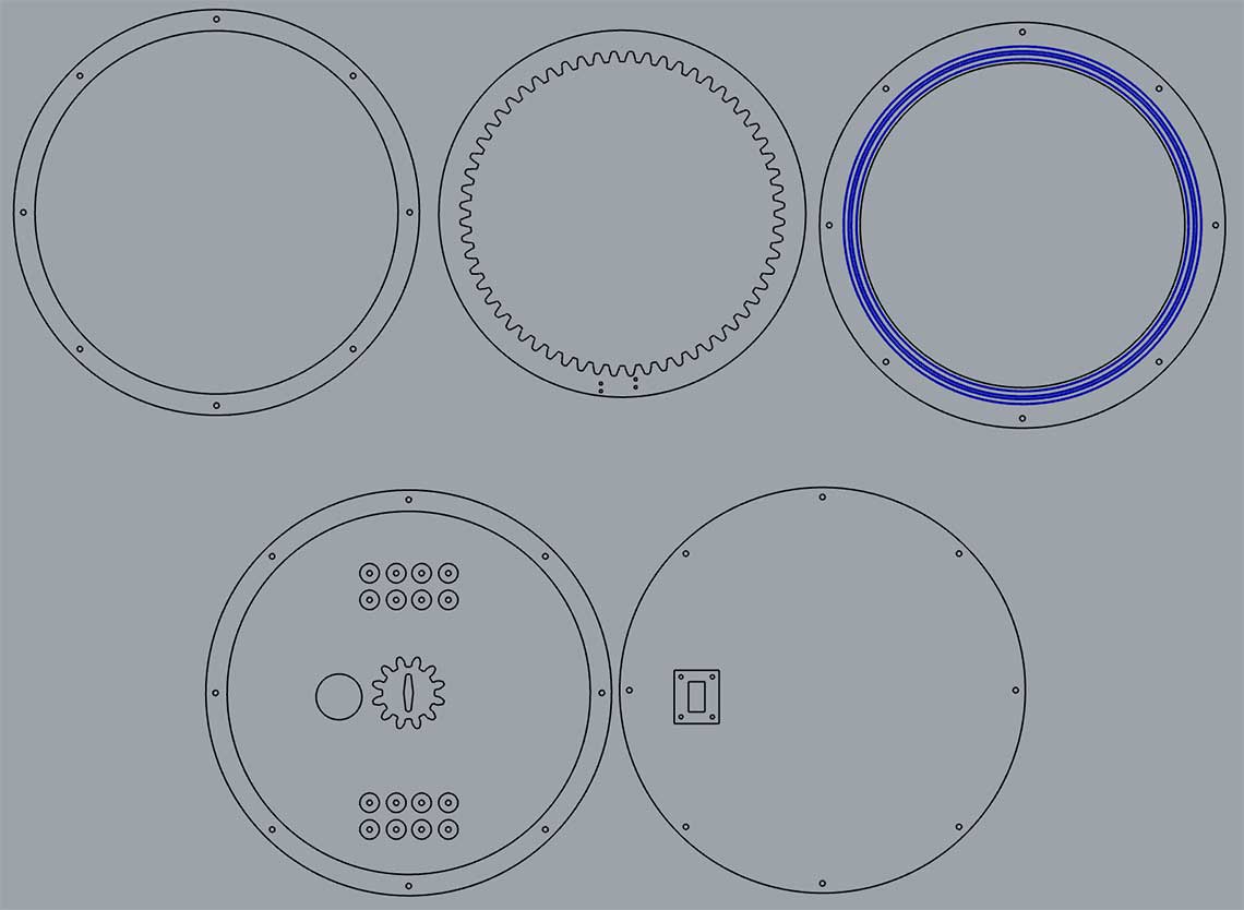
As I explained in the Mechanics section, for the display of the minutes, I designed a system based on gears and the use of a continuous servo motor.I did all the design in 3D with Rhino, and I extracted to outlines from the 3D model to laser cut the parts :
 I used 4mm thick birch plywood, which I cut with the following settings :
| Parameter | Value |
|---|---|
| Power | 80% |
| Power (corners) | 70% |
| Speed | 1500 |
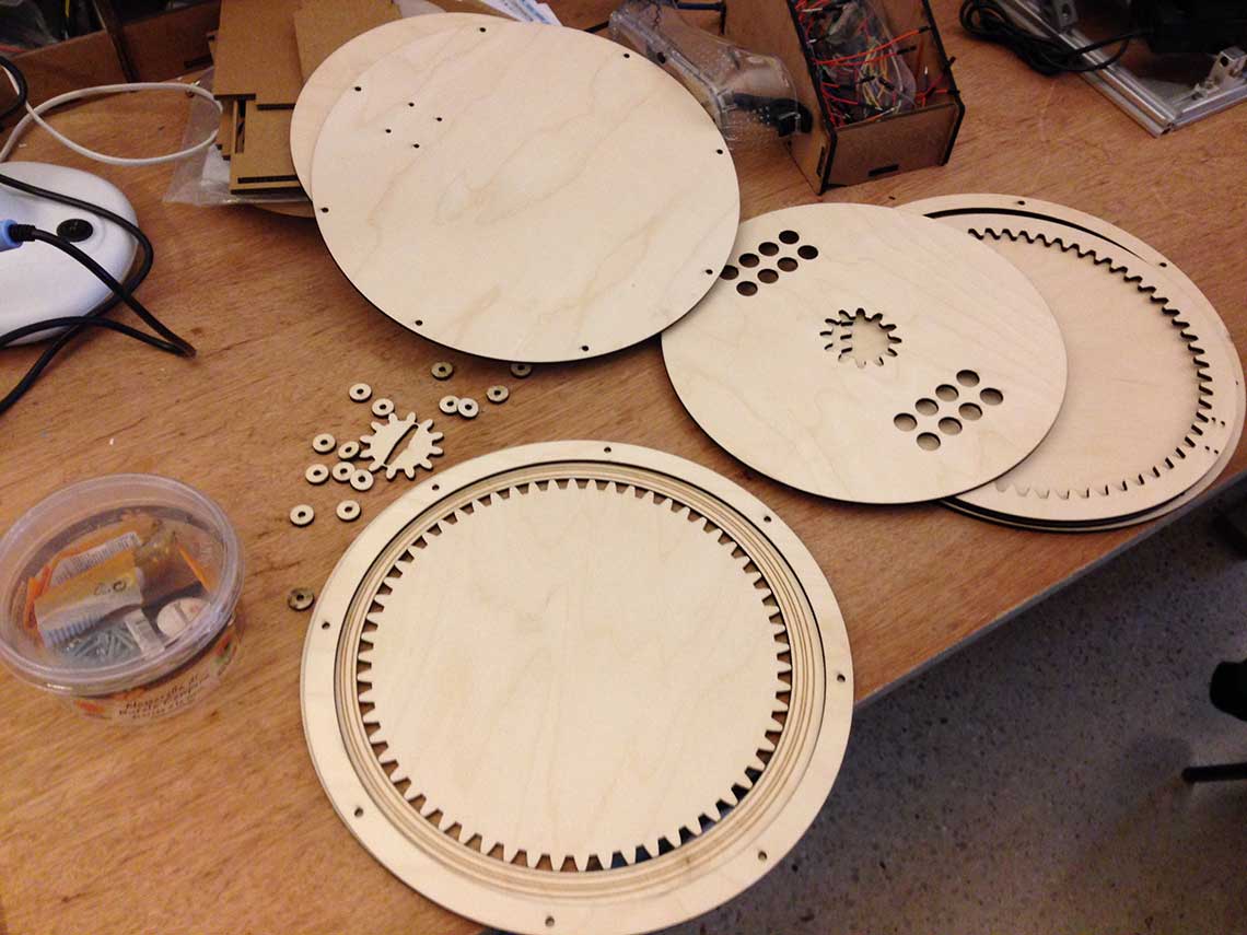 And the assembly steps :
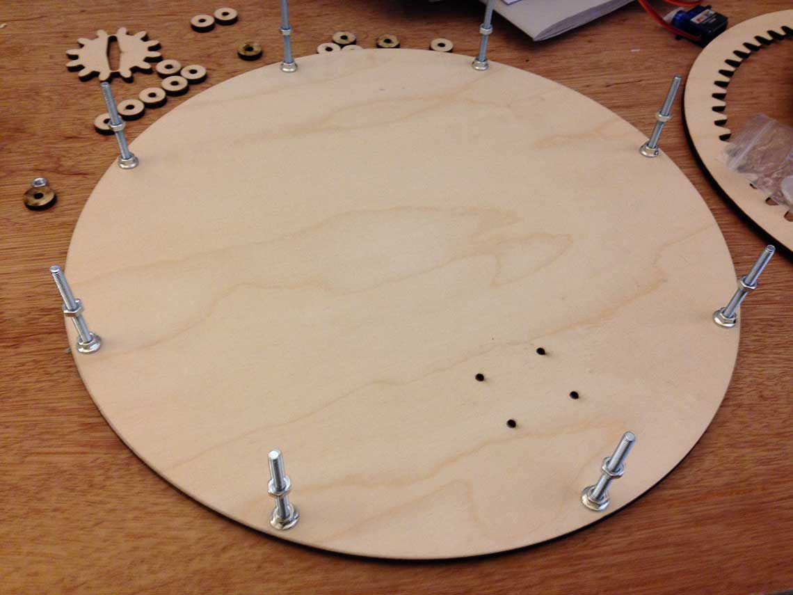
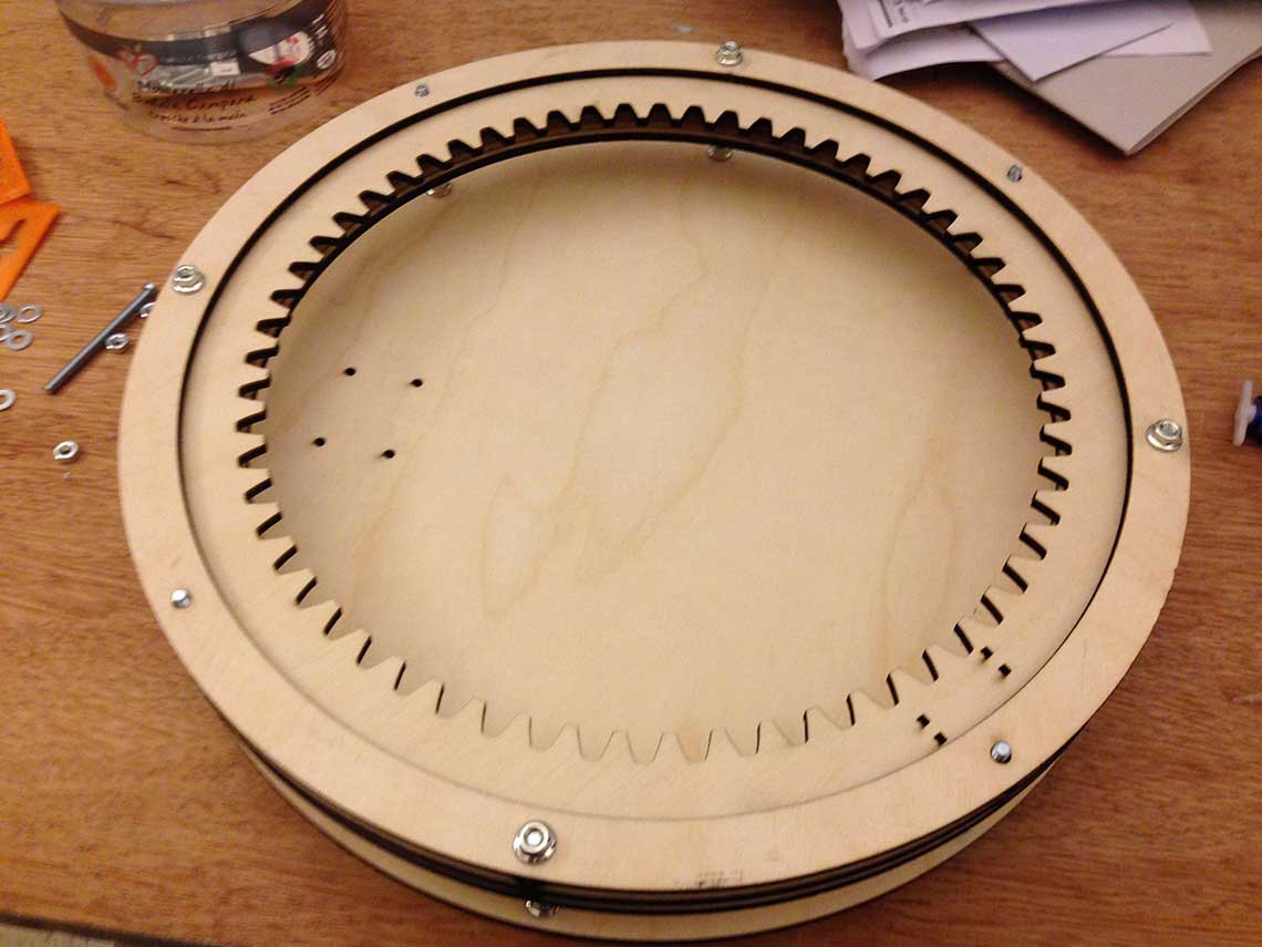 At first I was planning on printing some tubes to hold the bolts as you can see on the 3D model but I did not dit because the 3D printer was out of order.
I just used nuts instead which was even better to adjus the height of the bottom disk (the one with the copper traces).
At first I was planning on printing some tubes to hold the bolts as you can see on the 3D model but I did not dit because the 3D printer was out of order.
I just used nuts instead which was even better to adjus the height of the bottom disk (the one with the copper traces).Without the 3D printer I could not print the part that was supposed to hold the servo either, so I made a part that would do the job with the plywood.
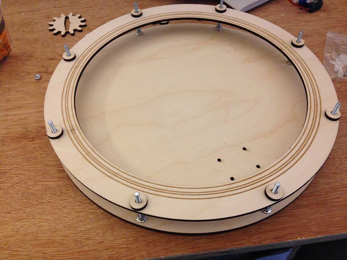
Here a some views of the servo's fixation :
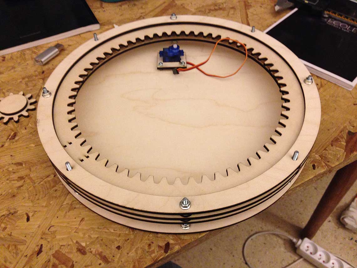
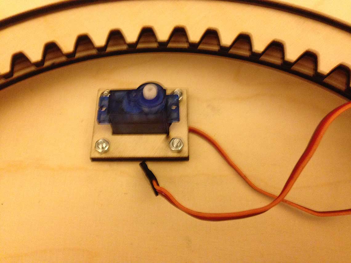
 Once the assembly was done, with some adjustements I could do a first test of the servo, using a sketch that you can find on the Electronics section :
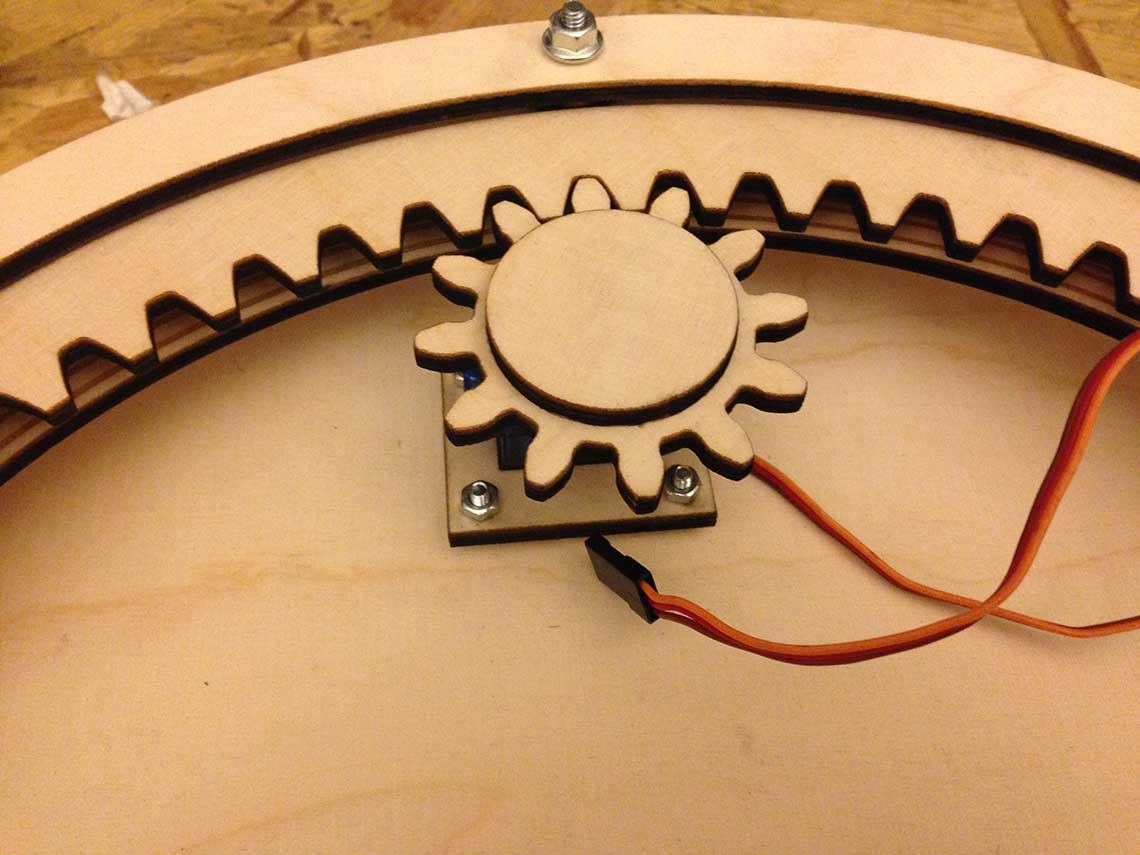
First observations :
- We can clearly see that some resistance is applied to the servo. As a result, it does not always spin at the same speed because sometimes, there is more friction of constraint.
- I see two combined reasons for that :
- 1/ The main gear does not spin completely freely. It is either because of the bearings or because it touches the disk below
- 2/ The contact between the two gears is too tight.
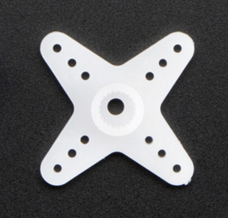
- Another problem is that the small gear is not attached well enough : it tends to bend sideways when receiving too much constraint. To connect the servo to the small gear I simply cut a hole in it with the shape of a horn :
 To be continued !
Update 07/06/2016
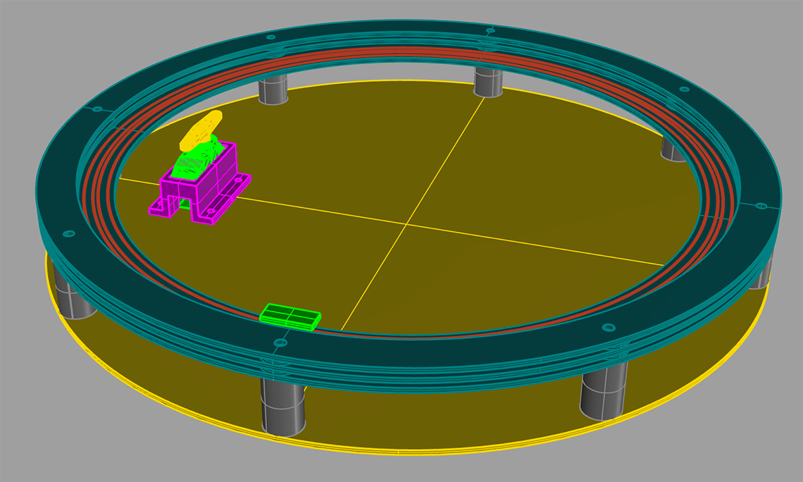
As explained on the Electronics page, I changed my mind about the minutes display. I will use 60 LEDs instead of a single moving one. So the structure of the clock should finally look like this :
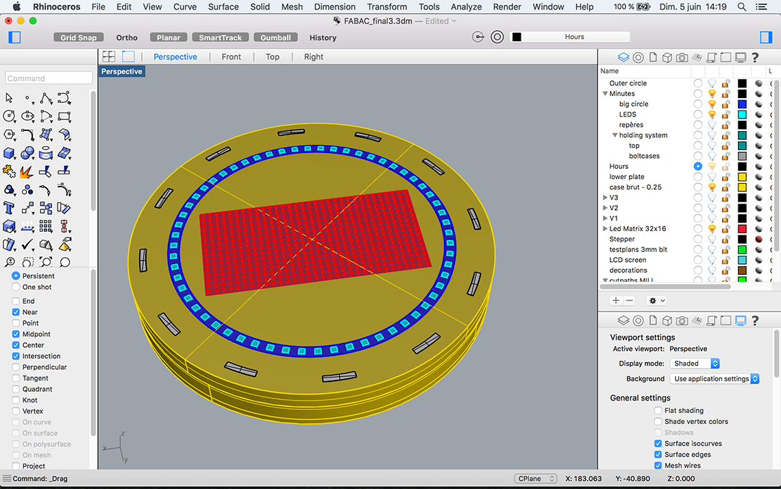 And on the inside :
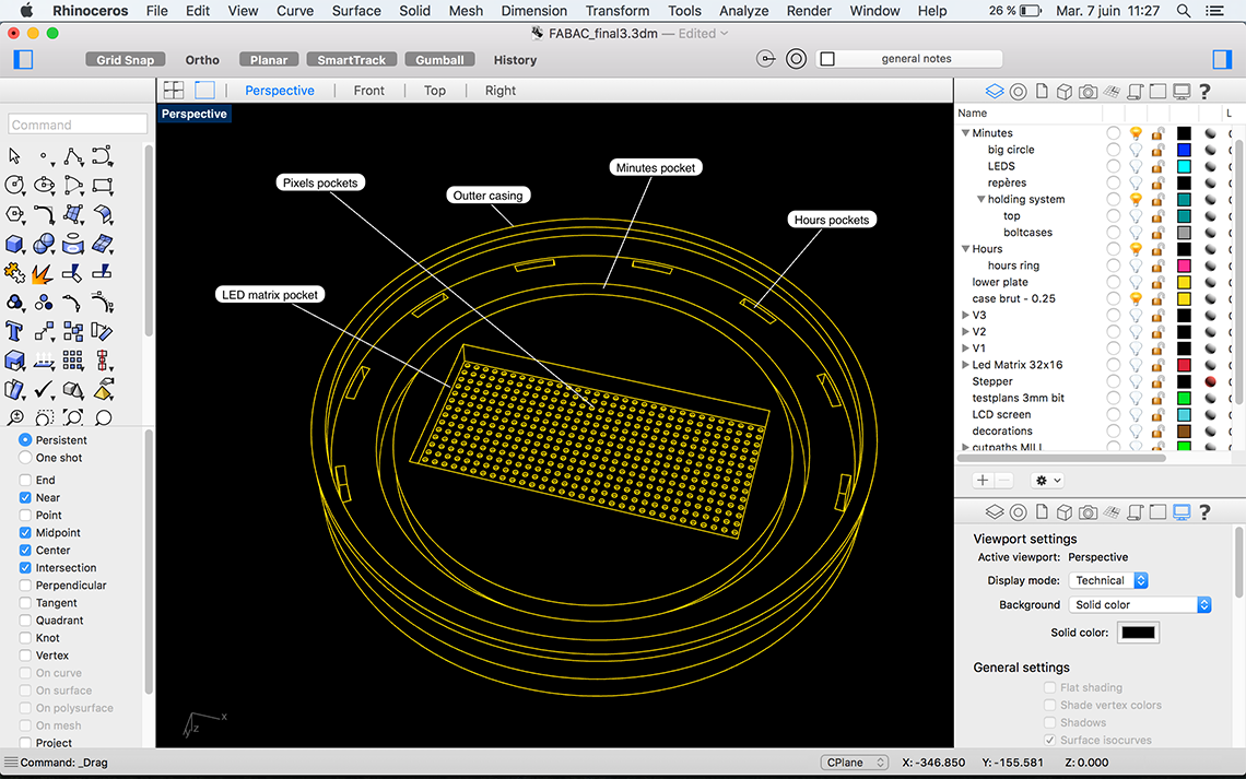 We will have :
• 12 individual pockets for the hours. The 12 LEDs will be mounted on a ring that will go on top of the pockets
• 1 large single pocket for the minutes : the 60 LEDs will be mounted on a ring which will go inside the pocket
• 1 pocket for the LED matrix : first layer just to fit the matrix inside - second layer with small circular pockets, one for each dot on the matrix
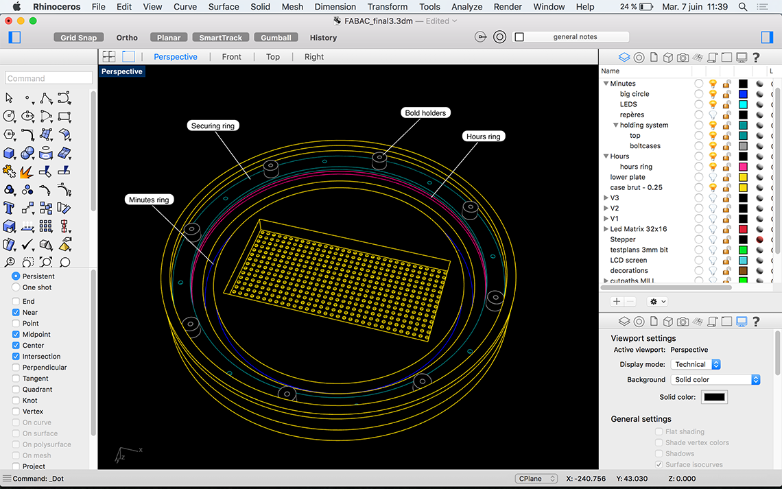 What I call "bolt holders" are just some tubes that I will 3D print and which will act as very thick washers, to hold the whole structure in place inside the clock.
The "secure ring" will be attached to the bolts and will maintain the minutes ring in place.
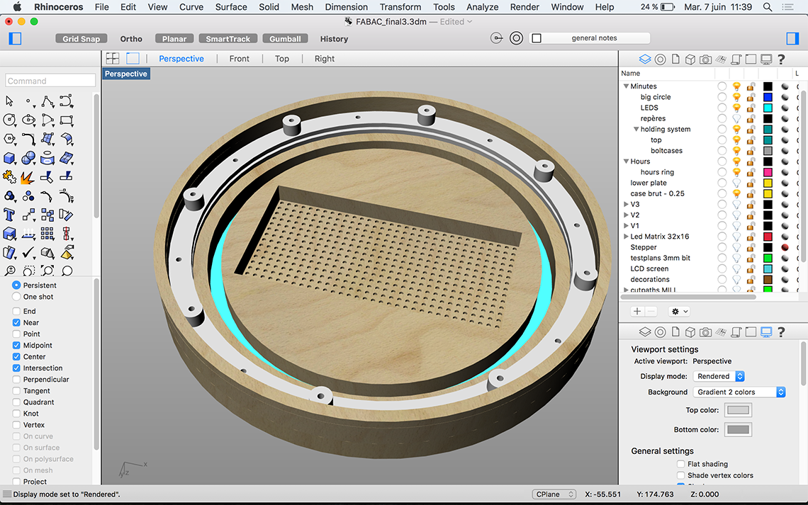
And here is a rendered view just this have a better idea :
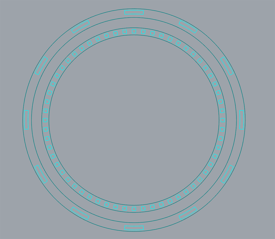
For the fabrication I will use three different techiniques. The "rings" for the LEDs, both for hours and minutes will be laser cut. I generated in Rhino the plan. The light blue curves will be engraved, to have guides on the rings to know where to put the LEDs :
 And the casing of the clock will be made with the CNC mill using 18mm plywood. Here a the plans for the pockets and cut :
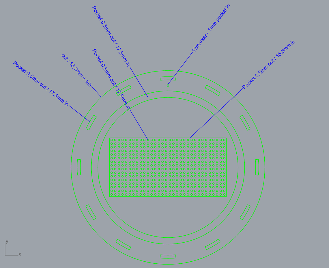 Here are the rings :
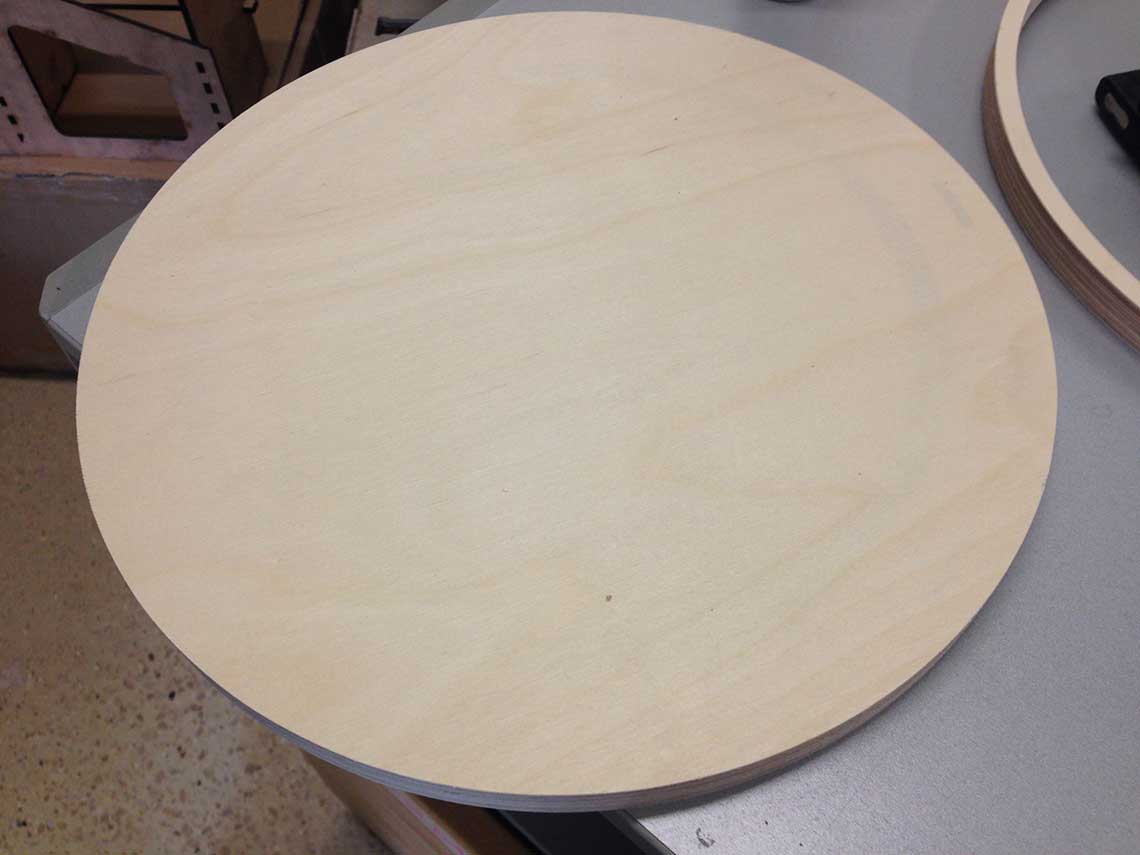
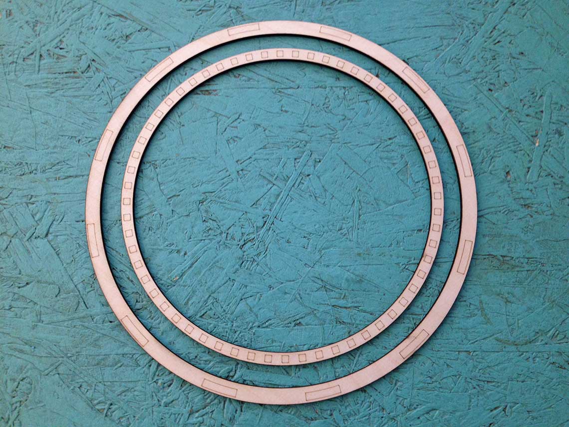 The first attempt of milling the surface of the clock was almost successful !
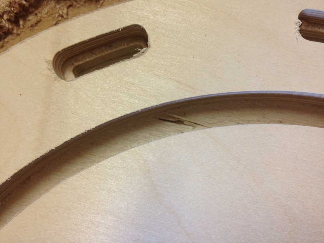
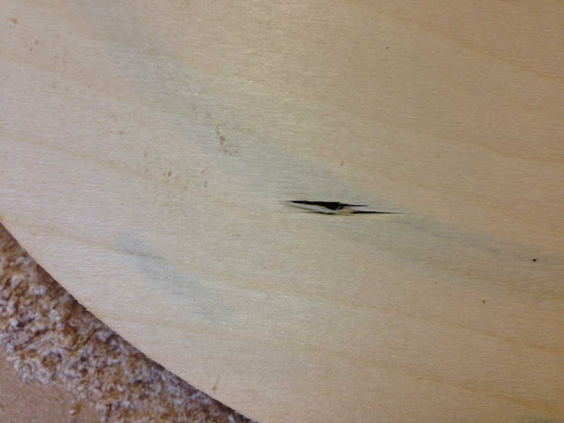
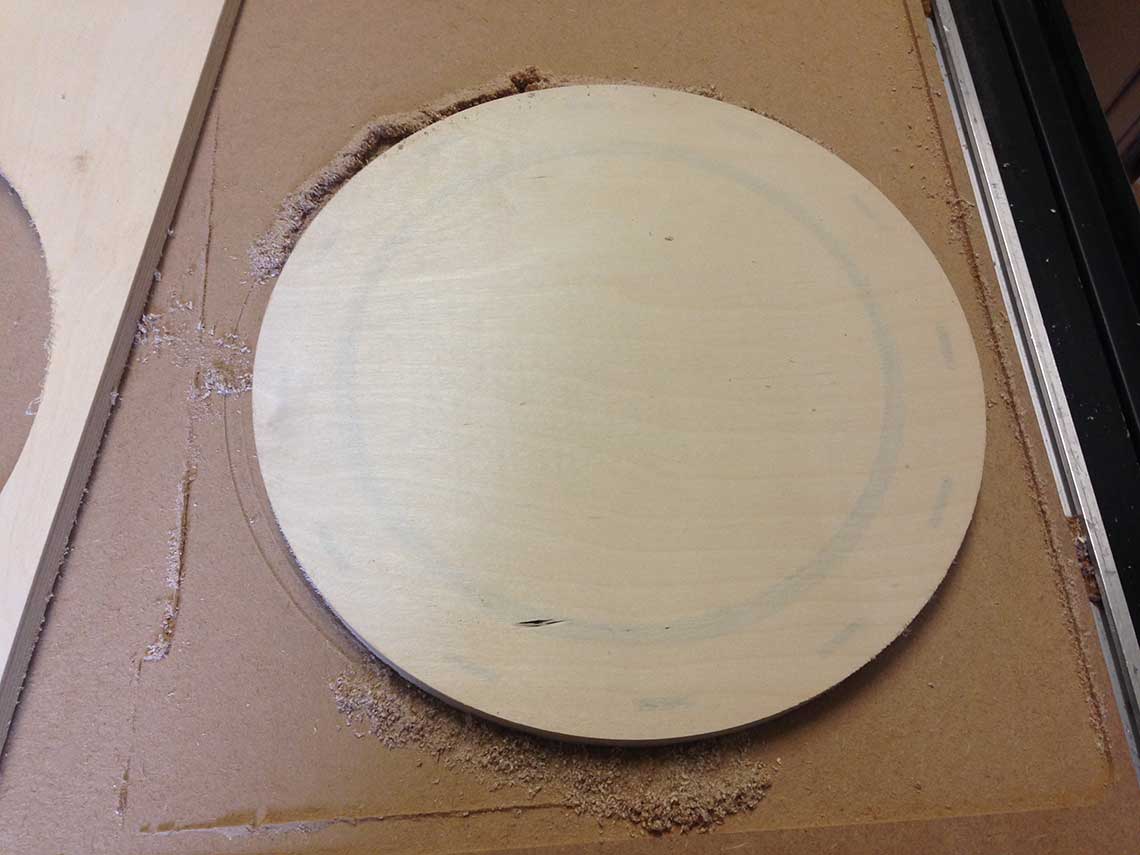 The result is generally very good but at one spot, the surface of the wood did not hold. Also, we can see that the parts where the wood was milled are darker, which I don't want. The thickness I chose was 0.5mm, I will therefore try 0.6mm to see if I can get a better and stronger result.
Those are the parameters I used in V-Carve. This time I did my zero on the surface of the sacrificial layer :
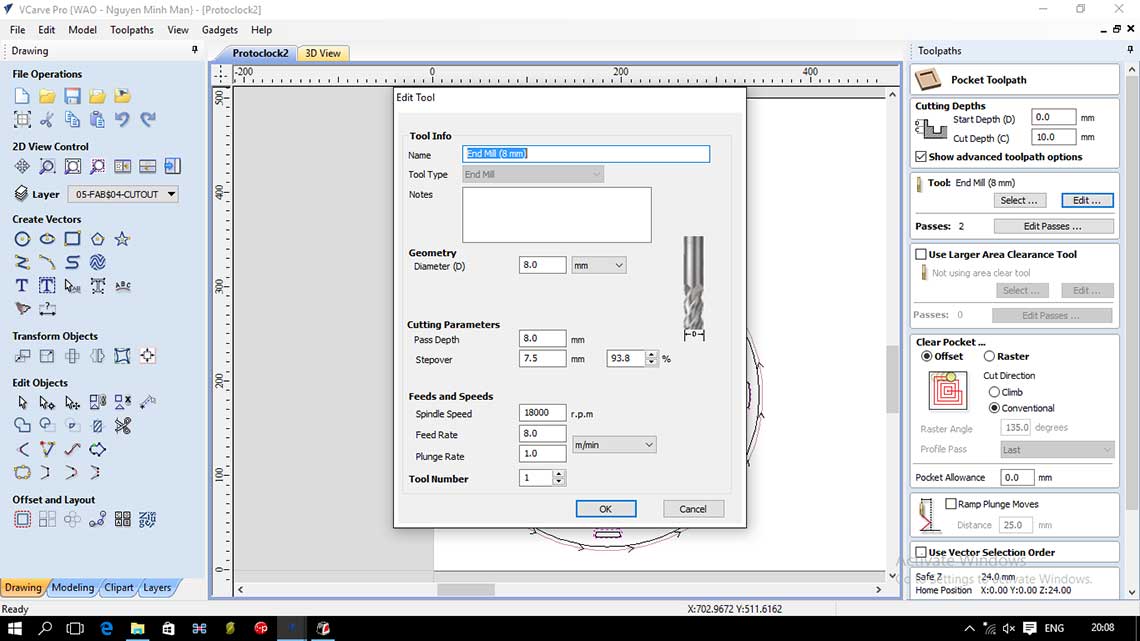
First job : 10mm deep pockets for the matrix, the minutes' ring and the hours, using a 8mm bit
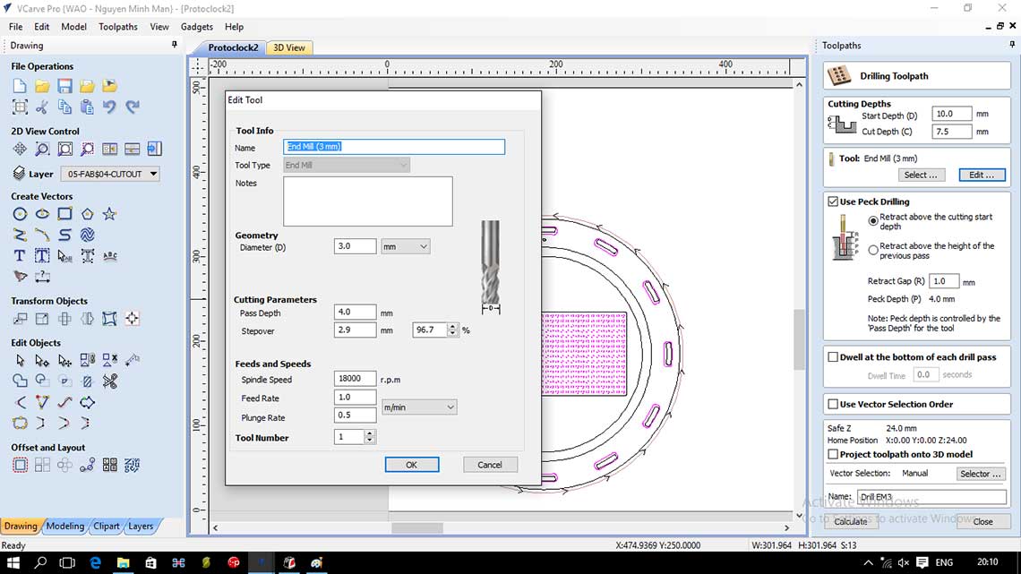
Second job : 7.5mm deep pockets (from 10mm to 17.5mm) for the hours and the matrix pixels, using a 3mm bit
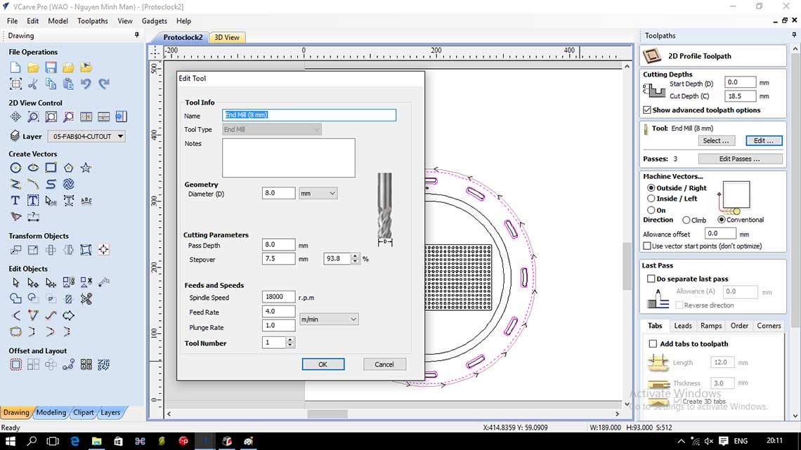
Third job : cutting the outline of the clock with a 8mm bit
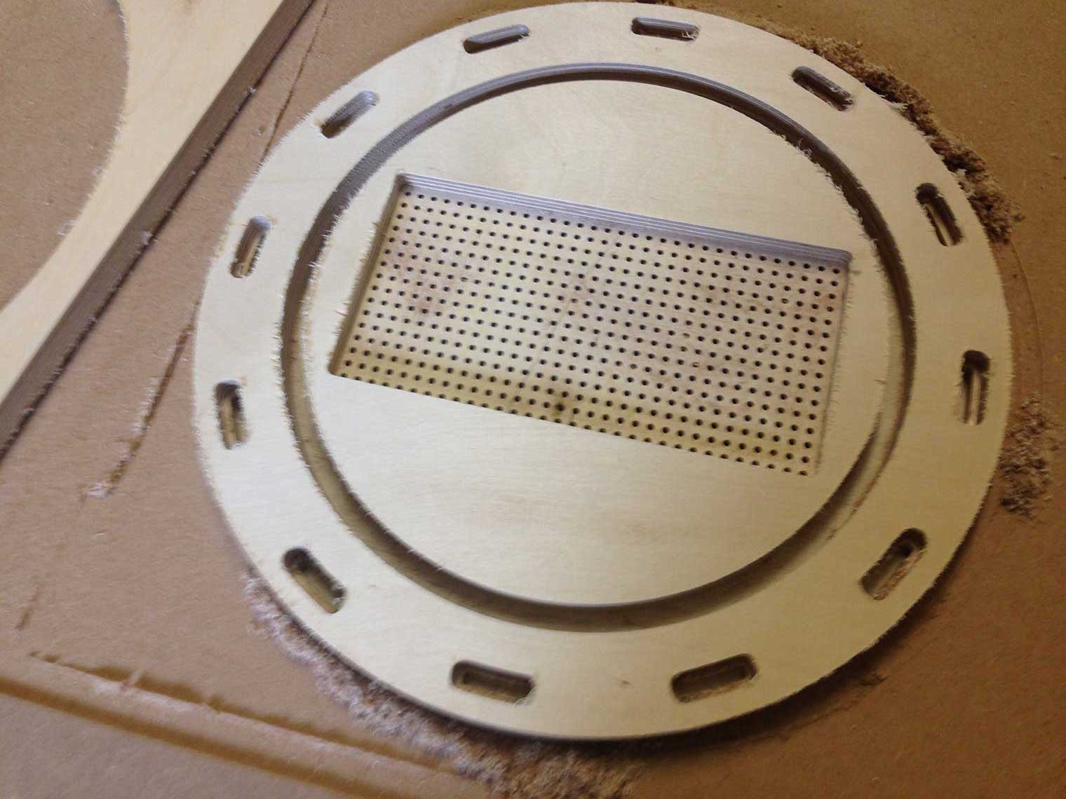
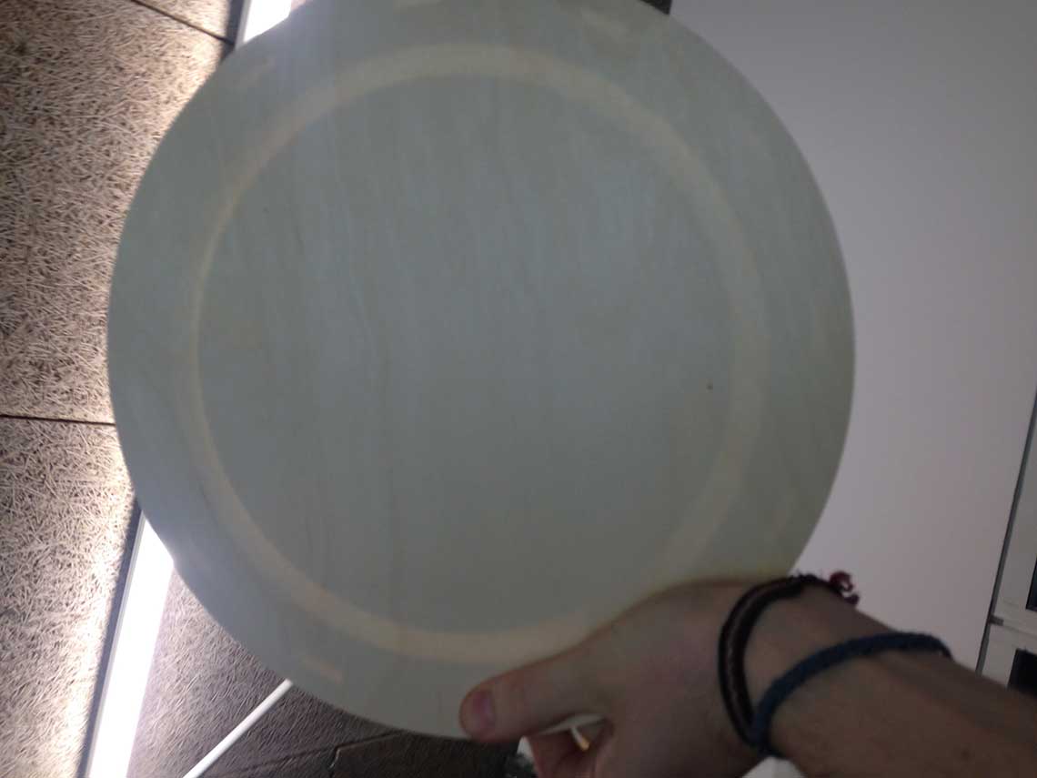
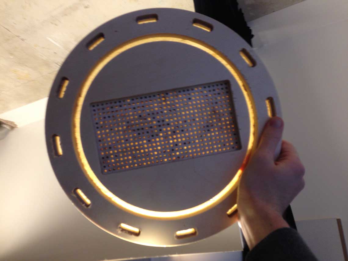 We can see here that the light passes really well through. Some dots are black on the matrix holes because there is still some dust inside.
Now this is the third attempt, with a thickness of 0.75 instead of 0.5. For the hour and minutes pockets it is just fine, but for the pixels dots I had to scrape the pockets because it was not translucent enough : the bottom of the pocket was too brown :