Computer-controlled cutting
Week 3's assignment
Tools used during this assignment : - Inkscape - Rhino - 123D Make - Illustrator - Vinyl Cutter - Laser cutter.
VINYL CUTTING
This week, we’ll be working around laser cutting. During the weekly lecture, we learned a lot about the different particularities of laser cutting as well as about the machines, materials, techniques, and softwares. Our assignment for this week will be to design, make and document a parametric press-fit construction kit. This is a bit of a challenge in only one week but it’s going to be exiting ! For this assignment, we will have to design something which is not related to our final project, so it will be like a small independent project, which is also cool. My idea is to create a construction kit for both a chess and a checkers game.
So first of all, I wanted to have on look on the different possibilities we had for 3D to 2D design. I find the UnrollSurf command in Rhino really interesting and I am sure it could be useful in the future !
I did a little test with a cone and it took me only a few seconds. The Curvature command can be as well pretty handy if you try to determine weather a surface is unreliable (developable) or not.

Another tool which I like a lot, and find very impressive, is 123D Maker. I also made a little test using a 3D model I found on the internet. I can't wait to try it for real, making for exemple a piece of furniture or a nice lamp for my leaving room made of cardboard !

But the main thing I wanted to look into was the clone function in Inkscape, because I thought it was the best way to make parametric design.
Before I began with Inkscape, I first did some drawn sketches, as a research for my kit. It was not necessarily the final idea but it gave me something to start with.
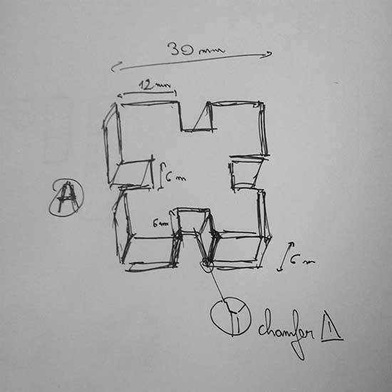
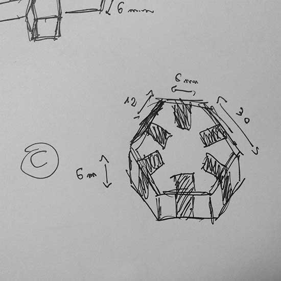
Then I designed a joint piece in Inkscape using the clone function for the joints : I created a joint, added a chamfer with the vector drawing tool and then cloned it to have four of them.
I will use cardboard first, to make some tests, so I set the width of my joints to 6mm. Later I will maybe switch to plywood if I am satisfied with my tests’ results.

First problem I had is that when I modified the width of my original joint, it did not stay centered on the edge of the piece. So I would have to move each joint separately if I wanted to change the width.
But I found the solution on the link that Niel gave us : if you go to the preferences dialog box and change the clones behaviour to « move according to transform », then they all move at the same time if you move the original !

So now I just have to clone the whole piece as much as I want it to appear on my board.
…But : I realized that there is something that does not really work. If I want to have chamfers, with this clone option it is almost impossible to control precisely the size of my joints, once I have added chamfers. So I’ll have to proceed differently.
Finally I found out about the « block » option in Rhino, with allows you to insert a block that you can edit from a separate file. So I created a file only for my joints, defining the width and then I created a file for my shapes (the pieces of my kit) in which I inserted the joints’ block.
If later I wanted to change the width of the joints in my shapes, I would just have to change it in the black file and then it would change automatically in every occurence of my block.
After this, I had to do a little test on cardboard, to make sure my joint’s width was good and that my kit was really « press-fit ».
I had to try twice because the thickness of the cardboard was not exactly the same as it was suppose to be.
But finally it worked.


Then I spent quite some time designing the final kit. Each chess piece is made of two parts : one defines its type (peon, tower, fool, etc.), the other is neutral and acts as a base for the piece. But I can also combine two bases to get a checkers piece.
I also made a different part which would be used for the second set of checkers peons.
As for the board, I designed one that can be transformed easily from a chess board to a checkers board using the same joints as for the pieces.
The design of the pieces :
 The design of the board :

A little test to show how the parts allow to build either chess pieces or checkers pieces :

For the fabrication, this time I wanted to work with wood to have an even better-looking result, and for the sake of trying. I first did a test with only two pieces to be sure the joints worked fine. For this I used 90% of power, 80% for corners and then 1200 for the speed.
The result was fine although I would have a lot a sanding to clean the pieces ! After a while, I realized it would take me too much time given that I had nearly a hundred different parts to sand ! So I switched back to carboard.
So here is my kit with both chess setting and checkers setting :


In addition to my previous comments, here are some interesting and/or useful links that were presented to us during the regional review of this week :
- On this Pinterest board are some very nice examples of complex parametric construction kits.
- SVGNest is a awesome tool that automatically nests your svg files in order to optimize the space used on the material and therefore the time spent for cutting.
- Fab Docmaker is an app that allows fablab users to keep a record of the parameters they have used to build their projects with the different machines that are available. The app generates pdf files.
VINYL CUTTING
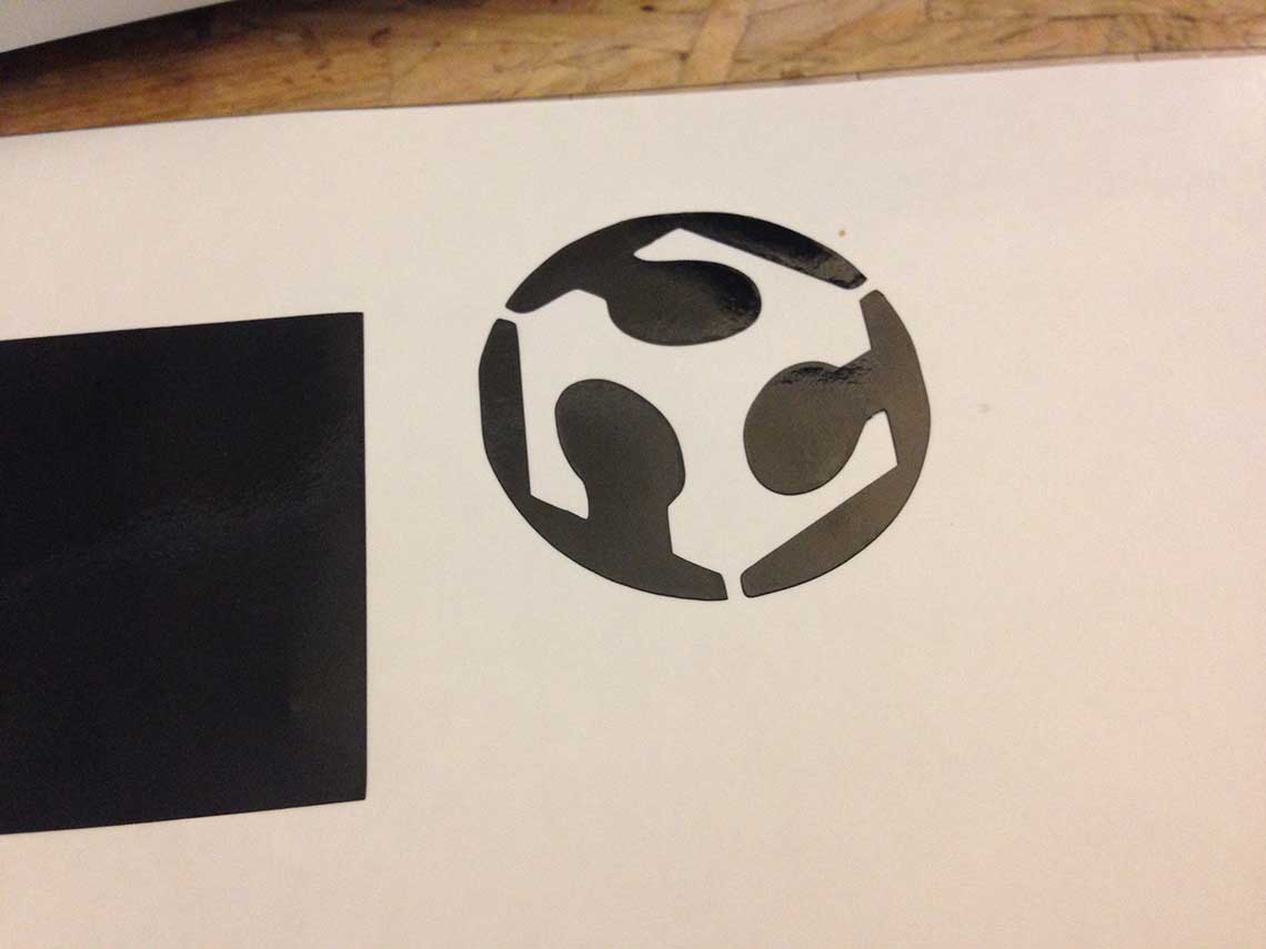
I also tested the vinyl cutter we have at the lab, which is a "Silhouette Cameo":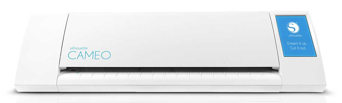 It is really simple to use : you just have to install the Silhouette Studio software to pilot the Cameo . First I started by doing a test with the Fablab logo. I just imported the PNG into the Silhouette Studio and it worked just fine :
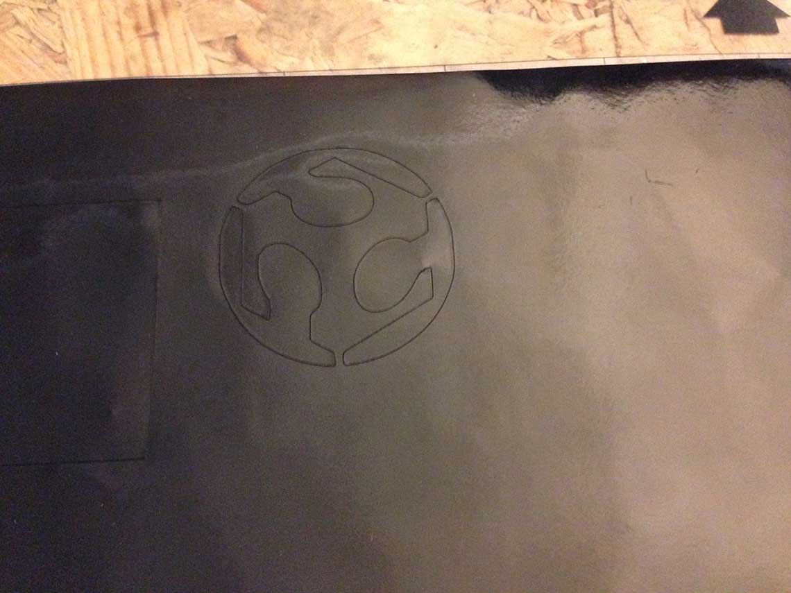

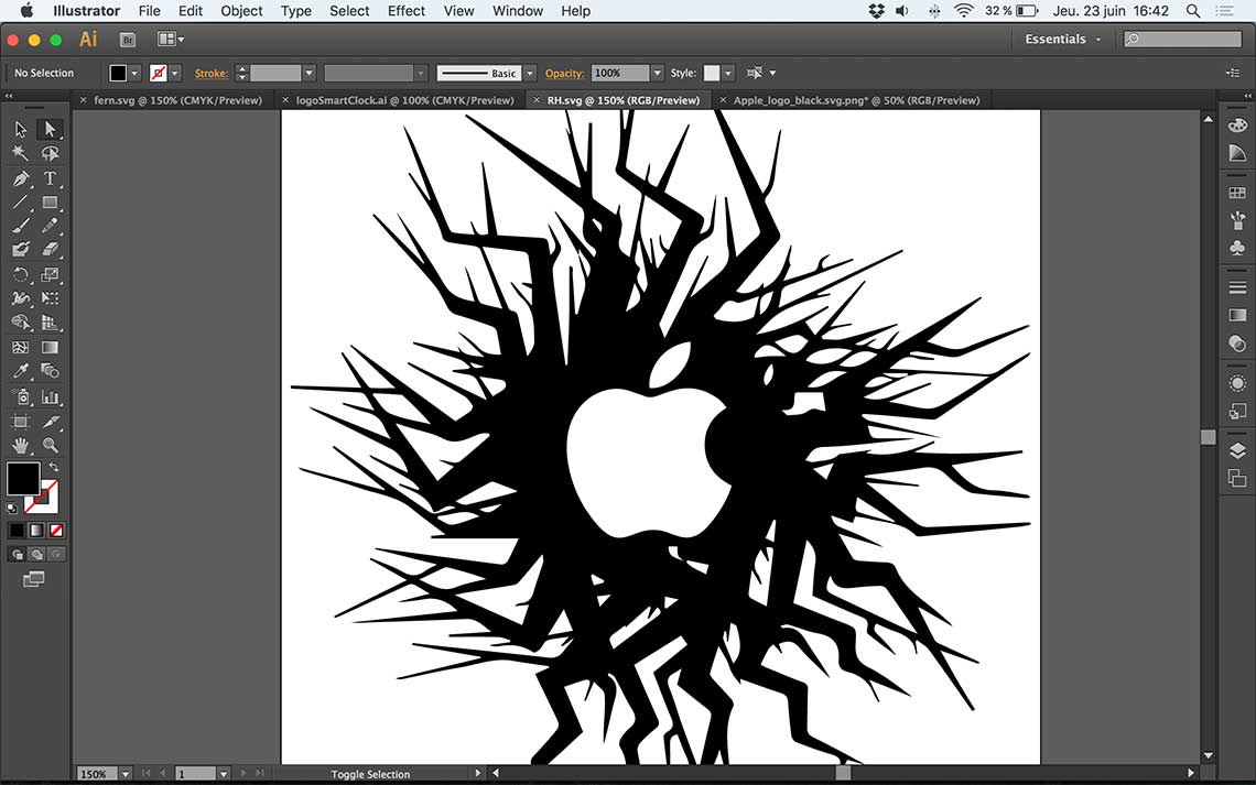 Once this done, I loaded the PNG in Silhouette Studio and vectorised it :
 The settings that I used where the default ones for vinyl cutting :
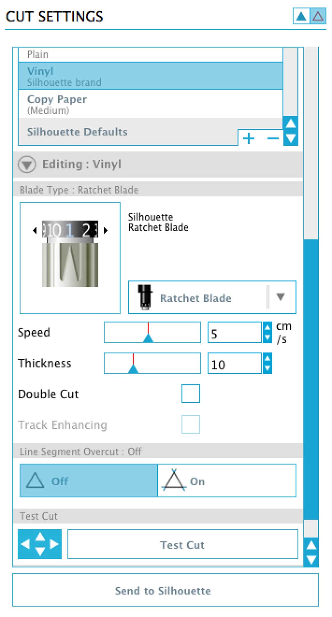 The cutting worked really well too ! I used some black adhesive vinyl sheet. Then I had to gently tear off the unwanted vinyl. Rather than just peeling it, I used a cutting knife to remove the extra material, because I had really thin details :
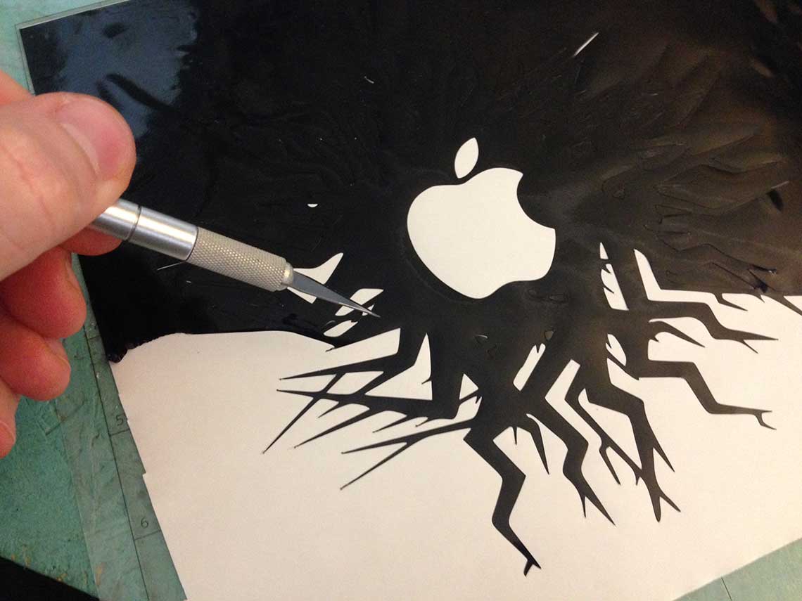
 Then I just had to apply the transfer paper on the cut material. I did a mistake and did not use the right one but it was not so critical :
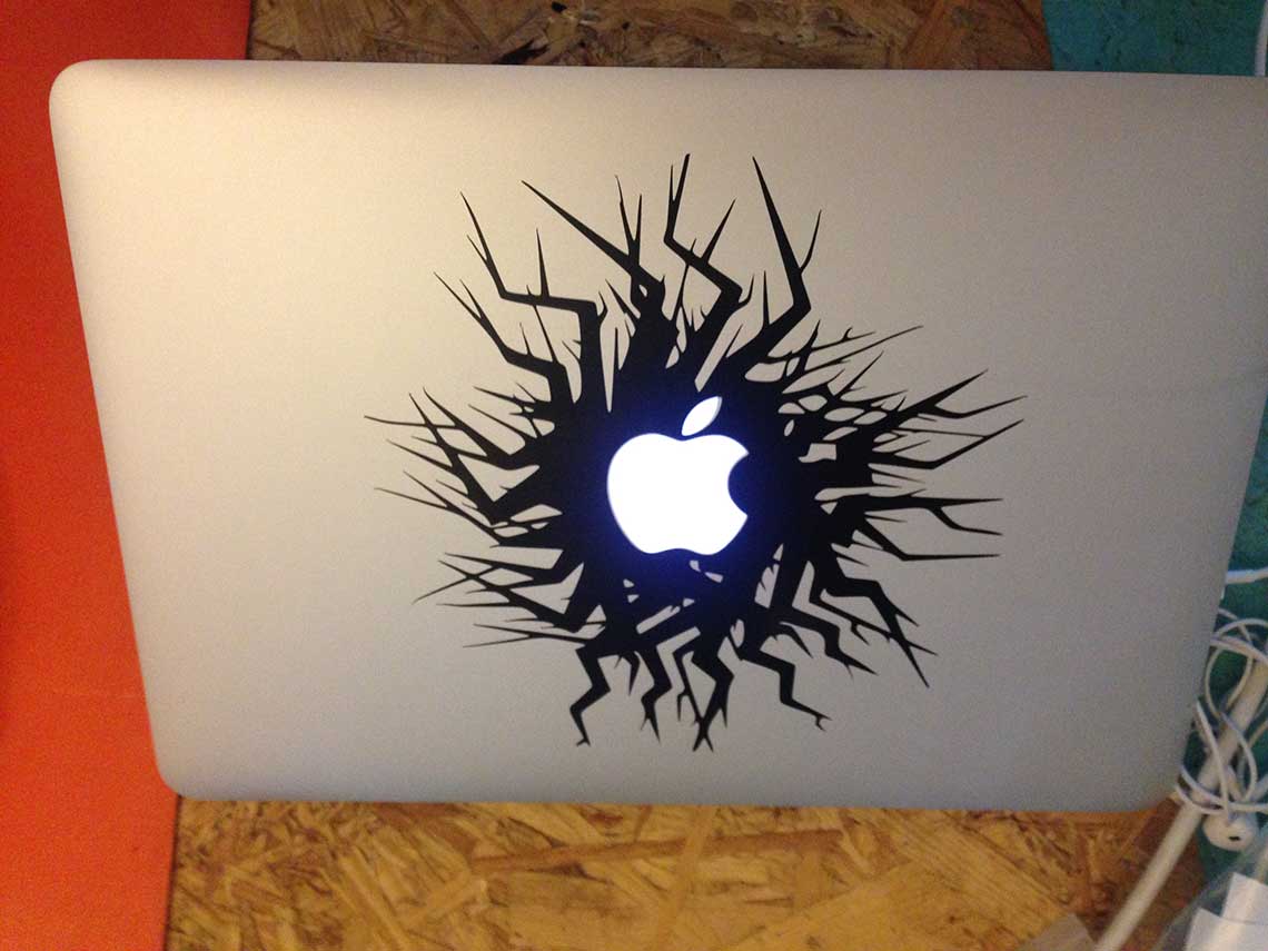
Here are the source files used during this assignment.