Assignment for week 4 Electronic Production
1.Make the FabISP in-circuit programmer
2.Mill the board
3.Solder the components on the board
4.Set it up for programming
What is the FabISP?
The FabISP is an in-system programmer for AVR microcontrollers, designed for production within a FabLab. It allows you to program the microcontrollers on other boards you make.
AVR microcontroller
An AVR microcontroller is a type of device manufactured by Atmel.
A microcontroller
A microcontroller is a single chip with build in features so it can run on its own, a mini computer. It sort of acts like the microprocessor on the motherboard of your PC but it does not need the motherboard or any other components to run. It is a lot simpler than PC microprocessor and deals with data in 8-bit chunks as its data bus is 8-bit wide.
An 8-bit microcontroller like the AVR doesn’t usually have an operating system, although it could run a simple one if required, instead it just runs a single program. Loading this program into the AVR is done with an AVR programmer or another microcontroller that is already programmed using a USB cable and 6-pin IDC to 6-pin IDC cable. Most simple machine like washing machines use a microcontroller
Milling the Board:
Currently in our lab we are facing some issues with the modela machine.So, I milled my board in IIT Bombay Fablab.
Steps for Milling
STEP 1 - Preparing the milling machine:
1. Turn the machine on.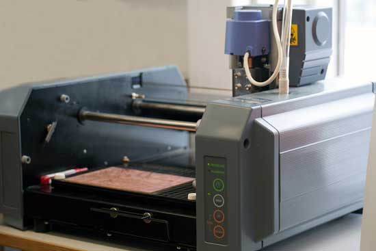
1.Fasten your board with the special double tape provided. NO dust underneath.
2.Make sure you have a sacrificial layer of material under your board. It will protect the machine and the milling bit when it cuts all the way through .
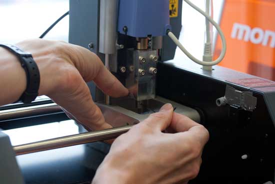
3.Set the correct milling bit in. First we use 1/64". Make sure its almost all in so it does not accidentally break when we move to the zero point. Use an allen key to fasten it. Careful not to over tighten. (The bits and the tools are on a magnet on the machine)
4.Move the machine to the zero point pressing VIEW button.
5.Use the DOWN button to set the machine in the lowest position, then take it back up a notch. (the purpose if moving the machine head up after putting it all the way down is to allow for it to move down from the starting position to cut into the material and it gives the milling bit the space it needs to travel above the board when moving from one milling position to the next.)
6.Now lower your bit with the allen key so it sits on the board. Fasten it carefully. (Note you might need to go first to step 8 if your board if far from the zero point.
7. Next open the Fabmodules and from there set your starting point. Zero point is an absolute position in the lower left corner. You need to play with the X and Y values to find where you want to start.
8.If for some reason you need to reset the milling machine, say to clear its memory of a job it did not finish. Press and hold in both arrow keys at the same time. Pressing up and down to clear the cach in the machine only works in view-mode (light next to view button turned on).
Download the board files.
There are two files needed for the milling. One for the traces (the boards roadmap) and one for the cutting outline. The reason why it is in two files is that two different milling bits are required for each job. We need a small flat 1/64" bit for the traces. For cutting the outline we need 1/32" end mill (flat). The third one is to show the placement of the components.
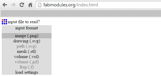
1.Use the FabModules to communicate with the Milling machine.
2.INPUT: Start by importing the image you are about to mill. First is the trace.png
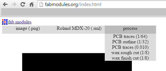
3.OUTPUT: Choose the machine you will use. We choose Roland Modela MDX-20
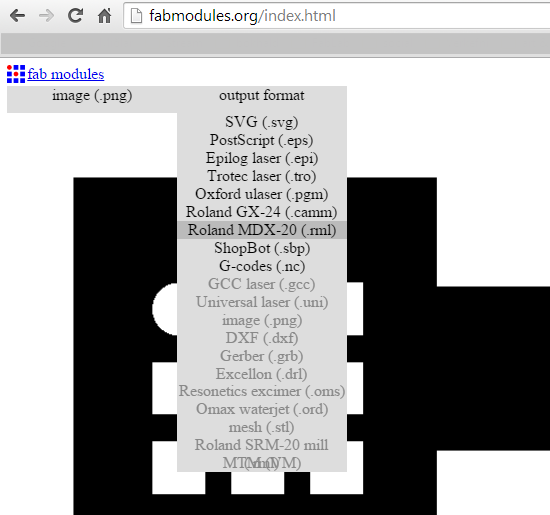
4.Pick the milling bit. - For milling the traces we need 1/64"
5.Set the starting point. Zero point is an absolute position in the lower left corner. You need to play with the X and Y values to find where you starting point is.
6.Press CALCULATE to see if the milling path is ok
7. NUMBER OF OFFSETS -tells you how many rounds it will be going from the cutting line. NOTE: black will go - (black-hole). Make sure your paths don't overlap.
8.Press SEND when ready and you're done!
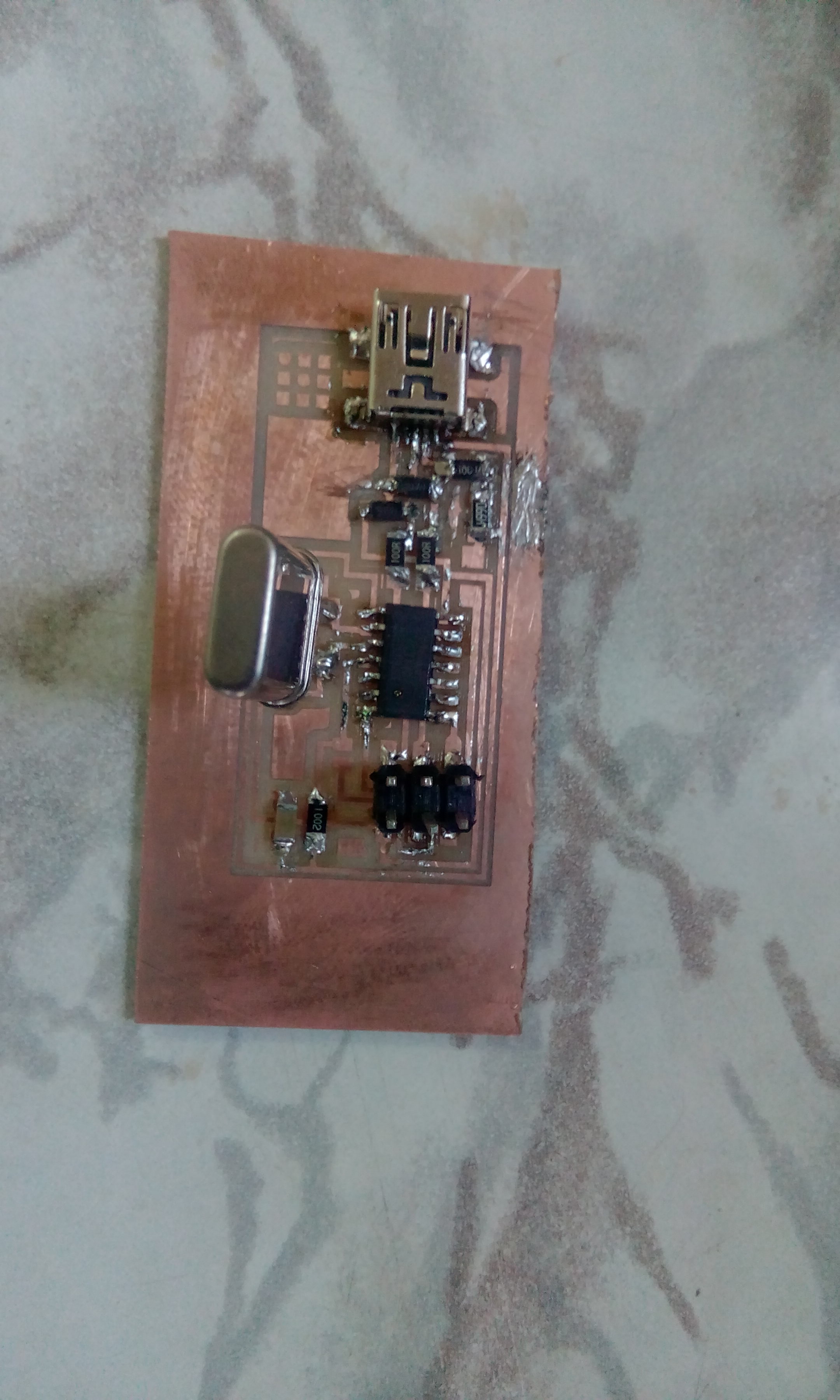
Soldering
To see what what components are needed and where they are supposed to go we need the FabISP board diagram.
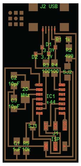
Required Component.
1. 1 USB connector
2. 1 ATTiny 44 microcontroller
3. 1 Capacitor 1uF
4. 2 Capacitor 10 pF
5. 2 Resistor 100 ohm
6. 1 Resistor 499 ohm
7. 1 Resistor 1K ohm
8. 1 Resistor 10K
9. One 6 pin header
10. 2 jumpers - 0 ohm resistors
11. 1 Cystal 20MHz
12. two Zener Diode 3.3 V
13. one usb mini cable