Assignment for week 11 Input Devices
This week challenge is to create and program a board that measures something. I was intrigued by the step response sensors, as they are really general purpose and allow to measure a lot of different things. For my final project I will also need to measure the pressure of the fingers, and this can be done using the step-response mechanism.
Force Sensor
The Flexiforce Pressure Sensor is essentially a variable resistor. When no pressure is applied, the resistance between the two outer leads is incredibly large, probably greater than 10 Mega Ohms (more than my meter can measure). When pressure is applied, the resistance measured between the outer leads lowers until you've reached the max pressure it's intended to measure. In this case that's about 25 lbs of pressure, and the current Flexiforce Pressure sensor I'm using measures about 50K Ohms when given that max amount of pressure.
You can test the range of your sensor using a multimeter. Just attach the two outer leads to the multimeter and set the meter to measure resistance. Then squeeze the sensor and watch the resistance value change.
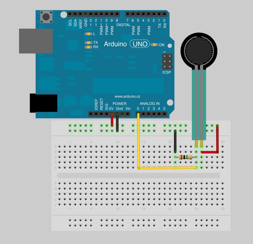
Now, let's read values with an Arduino. To do this, we create a voltage divider circuit with the Flexiforce sensor and an extra resistor. I picked 1M Ohm in this example because it's about in the middle of the Flexiforce sensor's dynamic range. Many other similar values could work as well.
Connect 5V to one side of the voltage divider, and GND to the other. In the middle, where the Flexiforce sensor and the resistor connect, connect one of the analog-in pins of the Arduino with a jumper wire. In this case I used pin A0. Here is a Fritzing diagram of the setup:
Software
Now that you have your circuit wired and ready, it's time to write some very basic Arduino code. This code is almost exactly the same as Arduino's standard AnalogReadSerial example. Let's take a look to see what it's doing:
// Flexiforce quick start example
// Reads A0 every 100ms and sends voltage value over serial

void setup()
{
  // Start serial at 9600 baud
  Serial.begin(9600);
}
    void loop()
{
  // Read the input on analog pin 0:
  int sensorValue = analogRead(A0);

  // Convert the analog reading (which goes from 0 - 1023) to a voltage (0 - 5V):
  float voltage = sensorValue * (5.0 / 1023.0);

  // Print out the value you read:
  Serial.println(voltage);

  // Wait 100 milliseconds
  delay(100);
}
The code is simply running in a small infinite loop every 100ms, or 10 times a second. In each pass through the loop, it measures the voltage on pin A0 and returns a corresponding value between 0 and 1023. 0 represents ground in this case and 1023 indicates A0 is sitting at 5 Volts. For other numbers in between, we can figure out the voltage by multiplying the measured number by the fraction, 5.0 / 1023.0. We then spit this value back over the Serial port, we can watch the values change in real time.
Board design
The first step of the assignment was to decide what parts of the board would be necessary and how many of them were not. As i will need to save as much space as possible. I redesigned the whole board in order not not have an additional microcontroller neither its own programming pins, so the board reduces considerably its size and its price aswell.
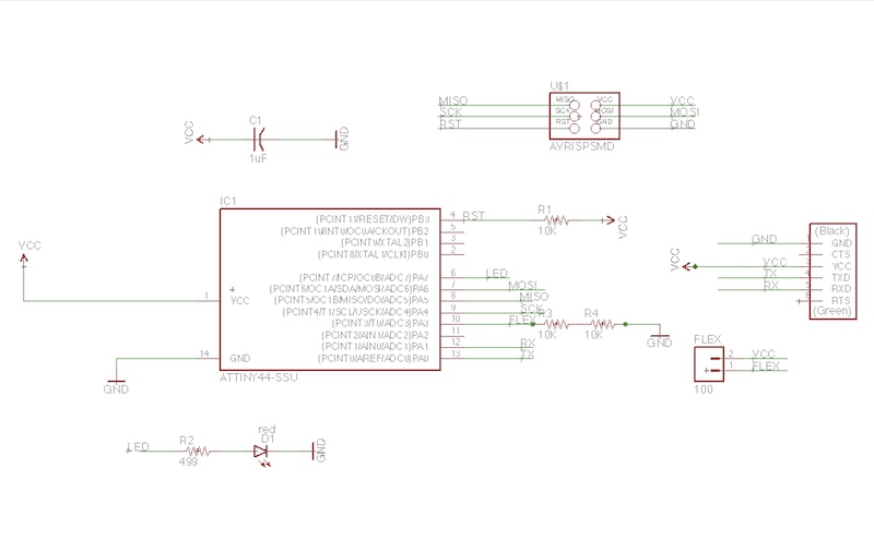
The board is redesigned with Eagle, incorporating just the necessary components:
1 Attiny 44
2 3 resistors 10K
3 1 resistor 499
4 1 capacitor
5 head pins conector (2)
6 ftdi header
7 head pin conector (6)
Programming with Processing
As the program of the Processing was a little bit more difficult and it was the first time opening this software, it took me longer not just to write the code but to understand the process that Processing is doing through Arduino code.
 import processing.serial.*;

 Serial myPort; // The serial port is opened