#05week
3D Scanning and Printing
tasks- - group project: test the design rules for your printers
- - design and print an object that can not be made subtractively
- - 3D scan an object (and optionally print it)
This weeks lesson was about 3d scanning and printing, the differences between the various processes and the advantages or disadvantages. of course a 3D object can be made by subtractive methods like milling or cnc machining, but for this week we will focus on those technologies that building 3D objects by adding material to a complete object.
There are a view technologies like stereolithography, FDM/FFF (fused-deposition modeling), extrusion, contour crafting, SLS (selective laser sintering) and much more. Also they use different materials to achieve their goals. Obviously not every system is for every object or project suitable. Sometimes only the combination of two or more 3D technololgies will bring the expected results. Nowadays a lot of comsumergrade 3D printers exist, affordable to enduser. Also a lot of 3D Services emerged due the demand of the market, they provide to the enduser those technologies that usually are on industrial level and more or less not easy accessible. But as with the FDM technologie when time goes by more and more will be accessible for everone.
There differences between the technologies also between the machines within the same technologie. They vary in costs, resolution building volume, production time and handling. An entry level FDM printer for example can use the same material an uses the same technology but will not achieve the same quality or speed as a commercial ones nor will be the handling as easy or straigtforward. But with more people get involved with 3D printers the more evolution there is.
Because of it open structure (most of the consumer level 3D printer are open source) the support is self-envolving through user-forums and blogs all over the world/internet. Sometimes the speed of response is unmatched when a problem occured and posted somewhere, where the community is active.
Of course the commercial ones cannot depend or rely on this kind of support, what not means that they won't also use this kind of sources - in our time the community driven sites are a very important source of information and feedback.
What's more the commercial solutions are not open source, they are propietary and not open to the public. Therefore the use of these sometimes differ from the opens ource ones. But the technology basically is identical. So the restrictions of the used materials are regardless the grade of the used machines.
FDM - Fused deposition modeling
is an additive manufacturing technology commonly used for modeling, prototyping, and production applications and it is one of the techniques used for 3D printing. Most of the machine that are used in the noncommercial level are based on FDM. Popular brands like Ultimaker, Makerbot, Delta 3dPrinter SpiderBot and more use this technology.
FDM works on an "additive" principle by adding material in layers. A plastic filament is melted and pushed through a noozle and supplies material to produce a part.
An small abstract from wikipedia: The technology was developed by S. Scott Crump in the late 1980s and was commercialized in 1990.[1] The term fused deposition modeling and its abbreviation to FDM are trademarked by Stratasys Inc.[2][3] The exactly equivalent term, fused filament fabrication (FFF), was coined by the members of the RepRap project to give a phrase that would be legally unconstrained in its use.
SLA - Stereolithography
is a process where a thin layer of liquid photopolymers is solidified by a ultraviolet laser beam steered by the design program, see the illustration below. The unsolidified resin is reused. It was invented in 1984 by Charles Hull who established the company 3D Systems to develop printing machines and the technology.The first machines were quite big in size, there a view companies that developed desktopsized machines to affordable prices and high resolution.Materials.
Photopolymer resins that are cured with ultraviolet radiation, they exist in variations that simulate other plastics such as ABS (Acrylonitrile butadiene styrene), Polypropylene, Rubber or castable wax supplied as liquids.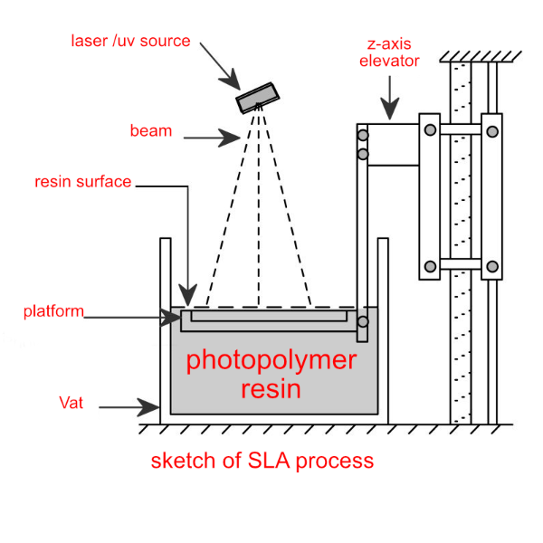
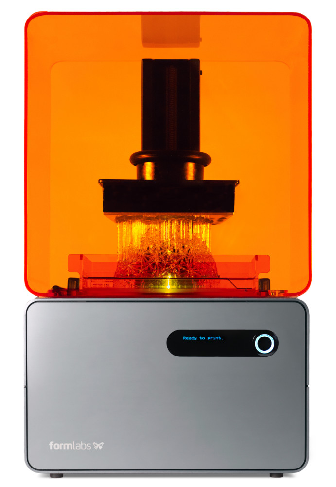
Below some images from the SLA printer we have in our FabLAb here in Kamp-Lintfort, the Formlabs:
failed stereolitho print

failed stereolitho print
SLS - Selective Laser Sintering
is an additive manufacturing (AM) technique that uses a laser as the power source to sinter powdered material (typically metal), aiming the laser automatically at points in space defined by a 3D model, binding the material together to create a solid structure. It is similar to direct metal laser sintering (DMLS); the two are instantiations of the same concept but differ in technical details. Selective laser melting (SLM) uses a comparable concept, but in SLM the material is fully melted rather than sintered, allowing different properties (crystal structure, porosity, and so on). SLS (as well as the other mentioned AM techniques) is a relatively new technology that so far has mainly been used for rapid prototyping and for low-volume production of component parts.Materials.
Fine powders of many metals, including titanium, gold, silver; also glass and ceramics.
Basic Information
Resolution
A major point for all described technologies is the resolution. There many factors that have influence to the resolution, like how many steps the motors have to do to make a full turn (the more steps are neccessary the finer the movement/resolution). This is so far true but usually to the cost of speed. Surely this dependency can be weakened by more powerful hardware up to a certain point.Supports
Some Technologies need to build supports where the object has a overhang if not the build will not succeed at all or will be missaligned in any matter. To name here are the FDM/FFF and Stereolithograpy procedures. The SLS/SLA/SLM on the other hand don't need extra support because the sourrounding material works as building material and supportmaterial in them same time.Wallthickness, clearences and fills
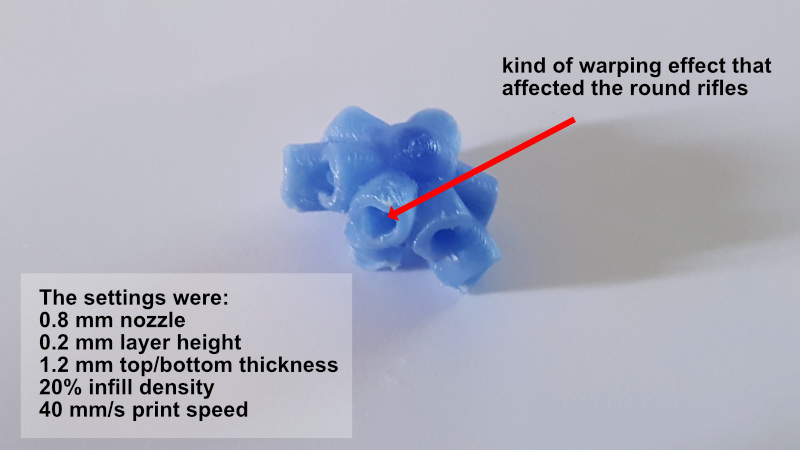
This characteristics have depednecies to the used material and the resolution the machine is capable of. As the minimum thickness for example can't be smaller than the noozle is capable to extrude. And the SLS for example is capable of extremly fine and thin structures but it is kind of useless if the object collapse as soon as it is taken out of the supporting material.So one of our assignments for this week was to test the rules and settings for our printers here in our lab, even that it was meant as a group task, after the group discussion where we talked about the settings and their effect on the prints, everyone of us did something on its own in the end. I guess it's because of different workflow everyone has. Because two of my fellow students printed an object similar to a calibration object. So I decided to print of one of my joints I will use later on in my final project as a test object. I decided to go for an ultimaker 2 just because I've heard so much about that printer and I was somehow curious about his quality. Also the slicer software CURA that comes with an ultimaker allows us to change nearly anything in the custom settings to achieve the best possible quality. But to do so it will take much more time than we have available for this assignment.
As on the last image visible - there was some warping effect that caused the opening of the rifle to come out somehow deformed. That way it wouldn't be very usefull for my project. After some research on ultimakers forum I rotated the object in a manner that the openings would be printed in a parallel position to the printbed - that solved the problem. Just that without changing any other settings. Tiny action but big effect!

I loaded the stl-file for the central joint into ultimaker's CURA slicer

This is the "layer view" - it shows how the object will be build up in layers

This is how the first 12 layer will look like - more or less

This is the first "Brim" layer
The final print with the standard settings showed some issues that I have to keep in mind
This is the reprint result just after rotating the object in cura, it took a bit longer to print because of it's orientation
The other part of our assignment for this week was to print something with the available 3D Printers in the FabLab that werre hardly or impossible to be made by subtractive ways.
So I designed a couple of geometrical objects that contained inner structures and overhangs combined with twisted or bended sections in Rhino.

I created UV curves from my sphere with the command
_CreateUVCrv
to define a startingpoint or edge, I had to select an curve/isocurve on the object

the unfolded UV contour is placed next to the object

Next step was to create a polygon within the unfolded contour
_Polygon
Than I selected & aligned the polygon in the corner for the next command
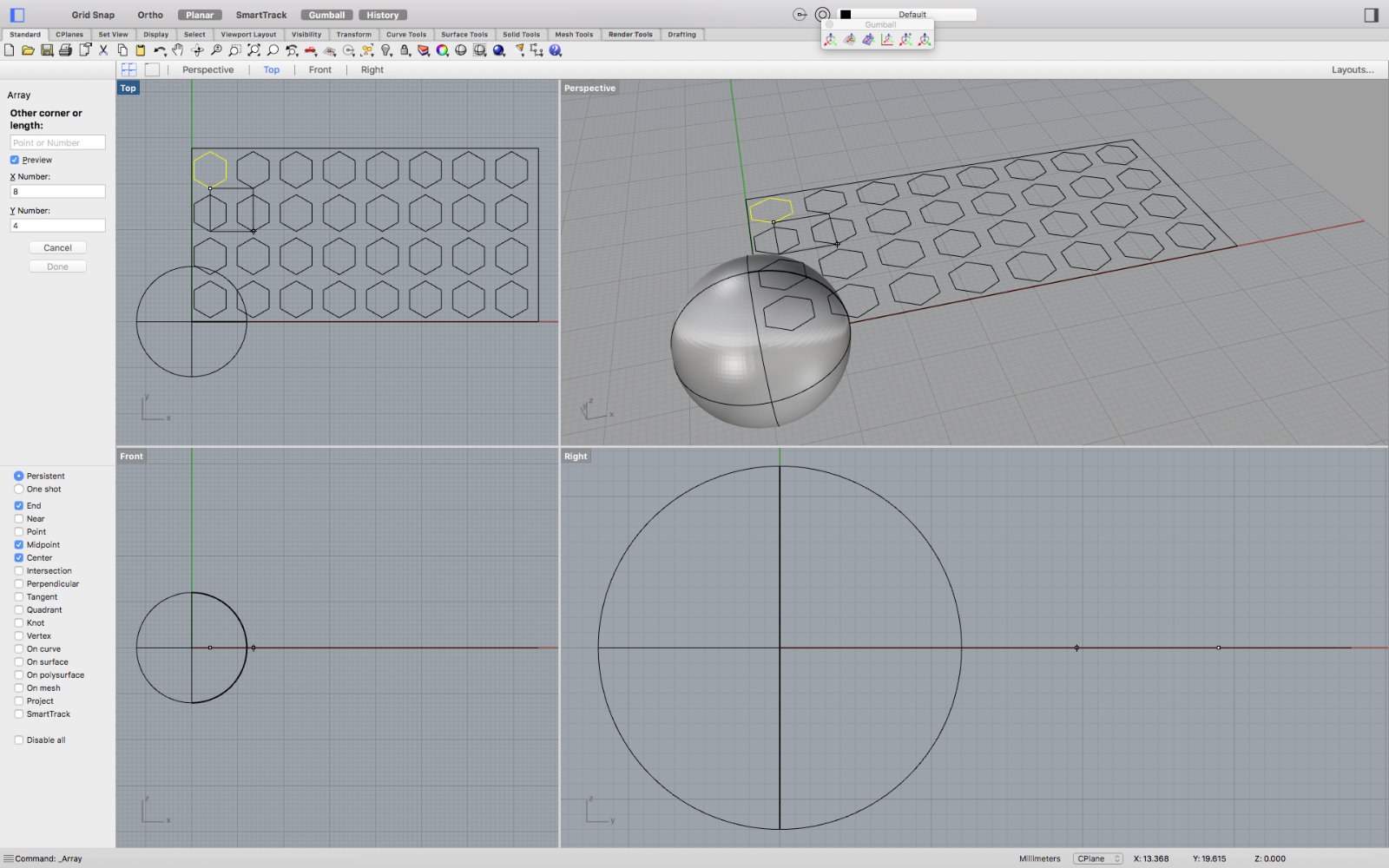
Now the polygone array is created with the command
_Array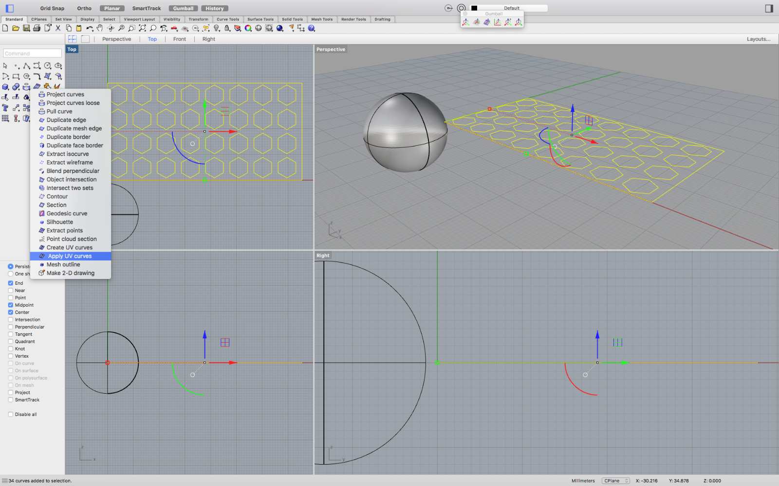
To get the array onto the sphere surface I used the command
_ApplyCrv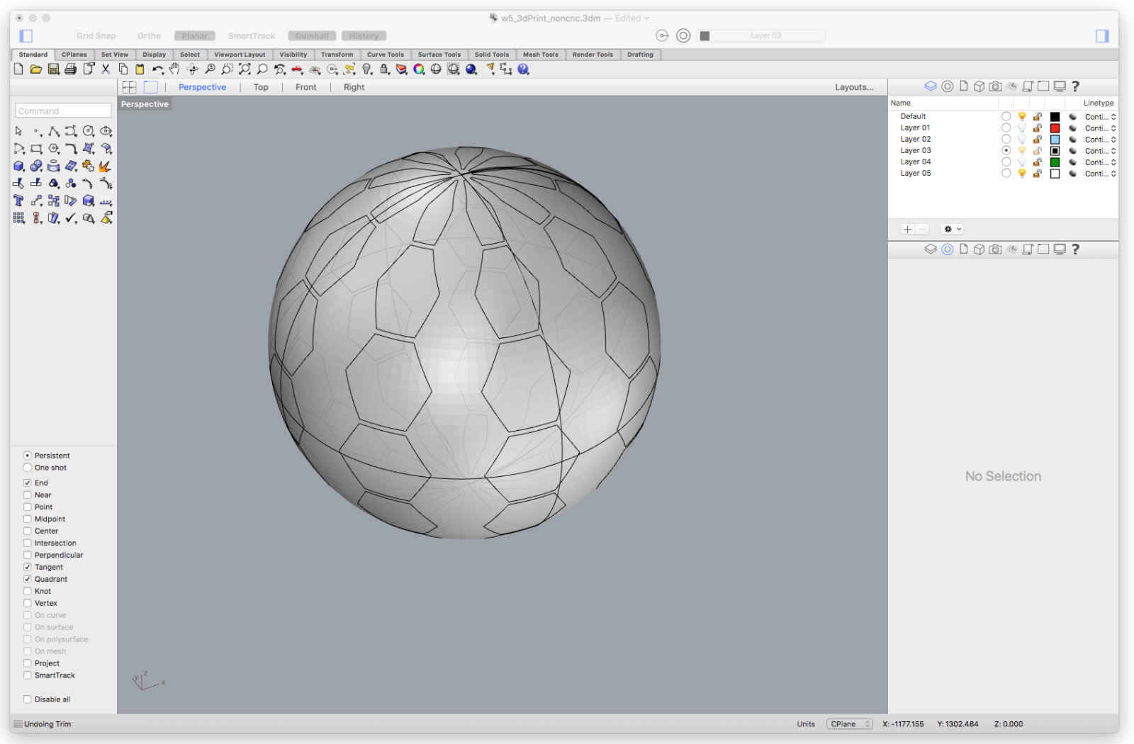
...the result looked alright...

To prepare the surface for further action I had to trim it
_Trim
...then I had to offset the leftover surfaces to the desired depth
_OffsetSrf
I'm nearly done, just a view steps.

I deleted those elements I had no use for...
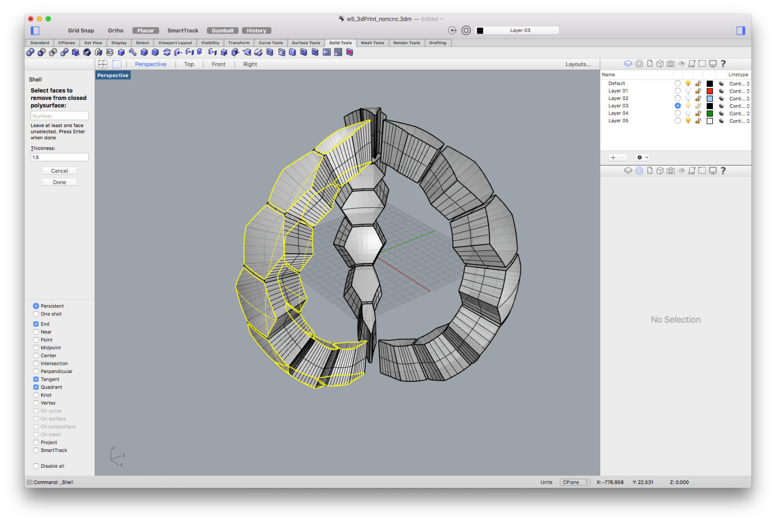
Now it's time for the command
_shell
...then I had to offset the leftover surfaces to the desired depth

Done!
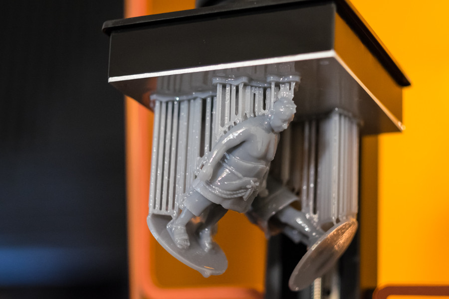
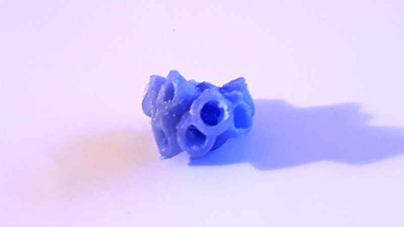
My hexagon file was choosen by me to be printed with the FormLabs Stereolithography 3D Printer. I thought because of it's structure it would be nice and interesting a half opaque appearance - I was thinking of planting some micro LEDs in the arms to use it as a desktop lamp... well i have to retry i guess. Below are some photos I took, it seems that the basin I used wasn't in the best condition. The clear bottom of the basin had minor scratches what maybe caused the faults. I will try again at a later moment with a new basin and on the second FormLabs. The pictures with the cube object were printed using the FFF/FDM process on an Ultimaker 2+, with a 0.8 noozle and standard speed settings.

failed stereolitho print

other part of the failed print
main part of the failed print
The Ultimaker 2 is a compact (by footprint meanings) 3D printer, but in it's class I believe one of the best. The results that can be achieved are amazing especially with the smaller noozles. Now for my prints I have used the 0.8 noozle - a midsize noozle, good for the most objects. It is a good choice between durability and resolution of the printed 3d objects.
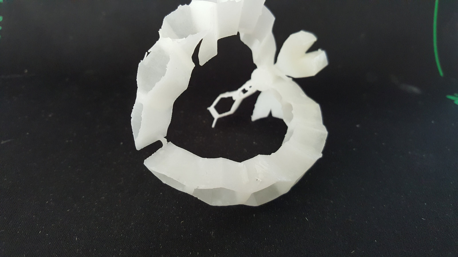
In my case now the standard settings generated of course automatically support for the overhangs and rings. Unfortunately was the object one of the smaller designs so that the support was very tight nearly bonded to the object. I tried to clean up the model but succeeded not completely - a part broke away....
My second run - was with manually added support-colons - but I guess the dimensions of those were a bit to small. Nevertheless the result looks really interesting. Kind of corall-style. No really the footprint and the diameter was too small and the support elements had no chance to get hold in time. So they were moved by the noozle and the following material...
Well I tried it a third time - now without any support. Just with a bunch of hope & believe that the "little" Ultimaker will do a good job if I let him. Just kidding - I was really curious how good or bad the result would be if the support was deactivated. And suprisingly the result was not that bad. With a bit grinding with a Dremel, Proxxon or similar tool it would look alright. Sure with a bit more time and some testing with the custom settings regarding the support the cleaning won't be a problem.
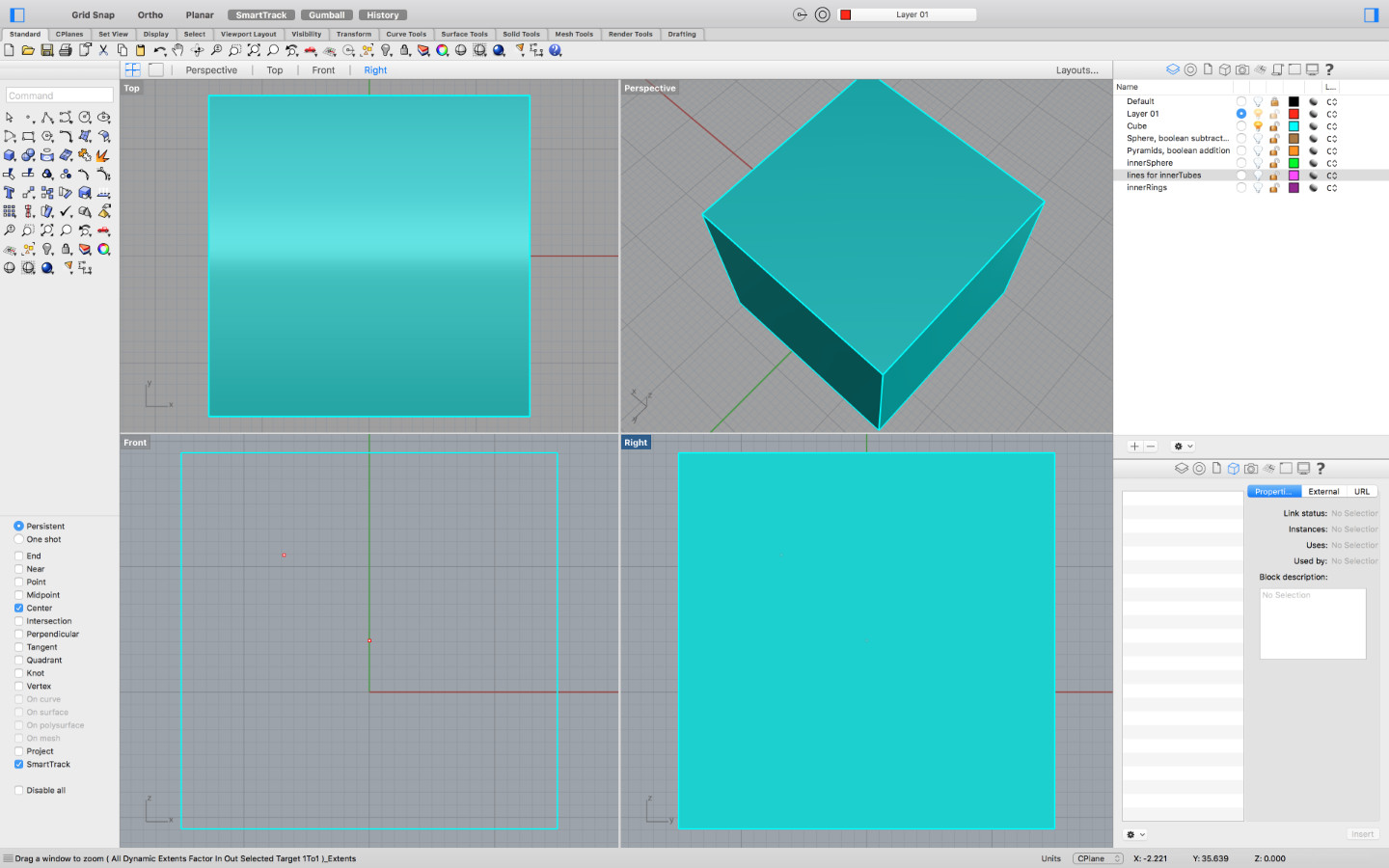
Step 1: I created a cube...

Step 2: I added a sphere to subtract from the cube..

Step 3: Here is the result from the boolean subtraction

Step 4: I added a second, smaller sphere in the center of the object

Step 5: I hide the cube & the sphere to work on the inner ringstructure

Step 6: After mirroring the ringstructure across...
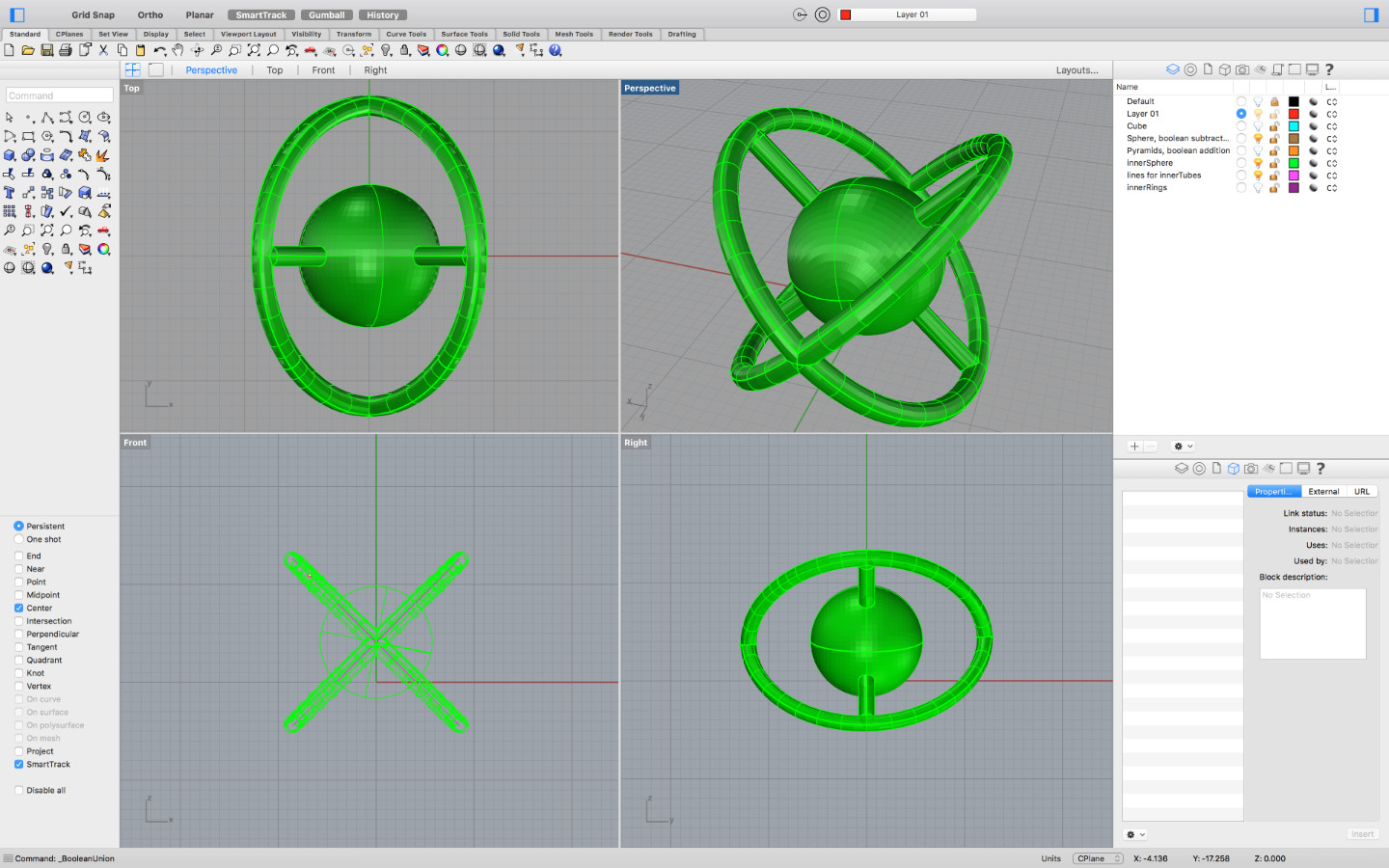
Step 7: ...I did a boolean addition with the inner sphere

Step 8: Then I added a pyramid that I rotated about 45 degree in two angles, to align it at the corner of the cube.

Step 9: Next I multiplied the pyramid with the function 'polar array', 4 copies, full circle

Step 10: Finally I mirrored the pyramids to the opposite side so that I had all corners covered

Step 11: I made all object visible again...

Step 12: After the final boolean addition I had my object ready for slicing for this weeks assignment!

This are the settings I have used for preparing and slicing my testfile for the Ultimaker 2 Extended

...on this screenshot there are those areas marked in red that need a support structure
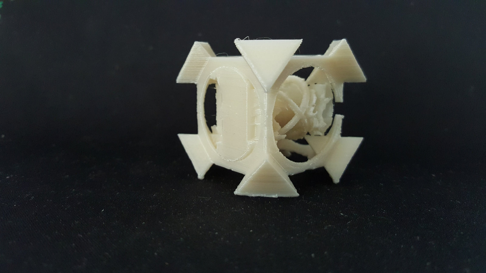
printed on Ultimaker 2+, 0.8 noozle
this cube is printed with automatic generated support
this cube is printed with automatic generated support

printed on Ultimaker 2+, 0.8 noozle
this cube is printed with manually added (to) thin support
this cube is printed with manually added (to) thin support

printed on Ultimaker 2+, 0.8 noozle
this cube is printed without any support
this cube is printed without any support

On this image I marked the settings I changed comparing to the standard settings
3D scanning
For our 2nd assignment I also used the 3D Systems handscanner Sense. It's very compact and therfor it can be used away. Despite it's size the technical data makes it clear that this is not a toy.Here the specs:
- Scan volume: Min: 0.2m x 0.2m x 0.2m / Max: 2m x 2m x 2m
- Dimensions: 5.08(w) x 7.08(h) x 1.3(d) inches / 12.9(w) x 17.8(h) x 3.3(d) cm
- Operating range: Min: 0.2m / Max: 1.6m
- Depth image size: 640(w) x 480(h) px
- Color image size: 1920(w) x 1080(h) px
- Field of view: Horizontal: 45° / Vertical: 57.5° / Diagonal: 69°
- Spatial x/y resolution @ 0.5m: 0.9mm
- Depth resolution @ 0.5m: 1mm
- Operating temperature: 10-40° C
- Maximal image throughput: 30 fps


3D Systems SENSE Handheld Scanner
For mac- and windwosbased systems the software can be downloaded here. Just take care that it is the right one you are downloading.
Ok, the software itself is similar to the scanner - very slim and simple. It is clearly addressed to enduser/consumer(moneywise too), because I believe that an engineer or other professional would like to have more control and adjustment possibilities.
When the application starts it asks the user what he wants to scan: Object or a Person, if object was chosen then the user hat to choose the right size between small - medium - large. If person was selected then the decision has to be done between head or full person. And actually that's it - the next step is just to press the start button and after 3 seconds the scan starts. Now this procedure is a bit tricky - to get a full 3D scan from a object/person - the scanner has to be guided around the target. During the scan process a constant distance (approximately 15 inches away) has to be kept, else the scanner will lose the tracking an the scan would be incomplete. Make sure that the image is centered on the screen. If there are gaps in the scanned data after a single pass, continue scanning to try to fill the gaps My experience and also the advice from cubify's support recommends a steady, not to fast scan process, first the lower sections of the object and afterwards the top sections. After a while, if the preview looks complete, the scan can be finished. After the scan is done, the scan can be edited by croping or erasing parts of the scan. With the button 'solidify' the scan will be converted into a solid object with all holes filled. At that stage there is still the possibility to enhance the scan in his visual appearence.
That was all - as i said a slim application. And as a result of this procedure following scans came out - not without saying that it was just one first try and my 'model' was a very special one. I will try later again to optimize my own handling because I had to promise this to my 5year old son ;)
Resumee
What I learned from this assignment, is to think about all possible options before changing a complete workflow or adjusting a bunch of settings. Sometimes a tiny change/adjustment can have a huge impact on the result. Like in my test case the rearrageing/turning the object other way round did the job. Sometimes small steps make the difference.

Optimus Prime scanned with SENSE Handheld Scanner
This is actually my 'Heroshot' for this weeks assignment
Downloads

This work is licensed under a
Creative Commons
Attribution-NonCommercial-ShareAlike 4.0 International License.