finalproject
Final Project
-
Idea, Inspirations & sketch
-
CAD design
-
prototyping & manufacturing
-
building process
-
spaceframe setup
-
the electronics
-
Software & configuration
-
Modifications in the software
-
preparing for testing
-
Issues
He Vessel
Resumee
Downloads
Index
Idea, Inspirations & sketch
My final project is a drone, not an ordenary one more a specialized one. It's a hybrid system based on a modular spaceframe structure that can be scaled to different pourposes. Thanks to the support of the helium filled vessel It should achieve a longer airtime as a second goal.They are hundreds of multicopters they compete by features and speed but nearly all of them lack of a reasonable airtime.
I prefer a higher airtime than topspeed. This would be more useful for Aerial photography or for example during an exhibition a indoor flight.
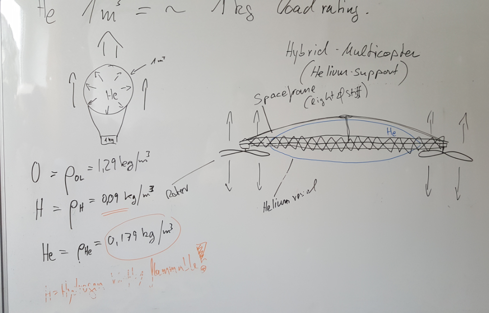
The main thought was to "marry" a multicopter (drone) with an Airship (Heliumvessel) in a manner that looked cool and functional. As I am a designer by profession it is always a natural automatism that my work has to "look" good in different meanings. So instead of taking a standard drone frame and mounting just a ballon filled with helium to it - I sat down and made my mind up how to design a new hybridcopter that meet my needs.
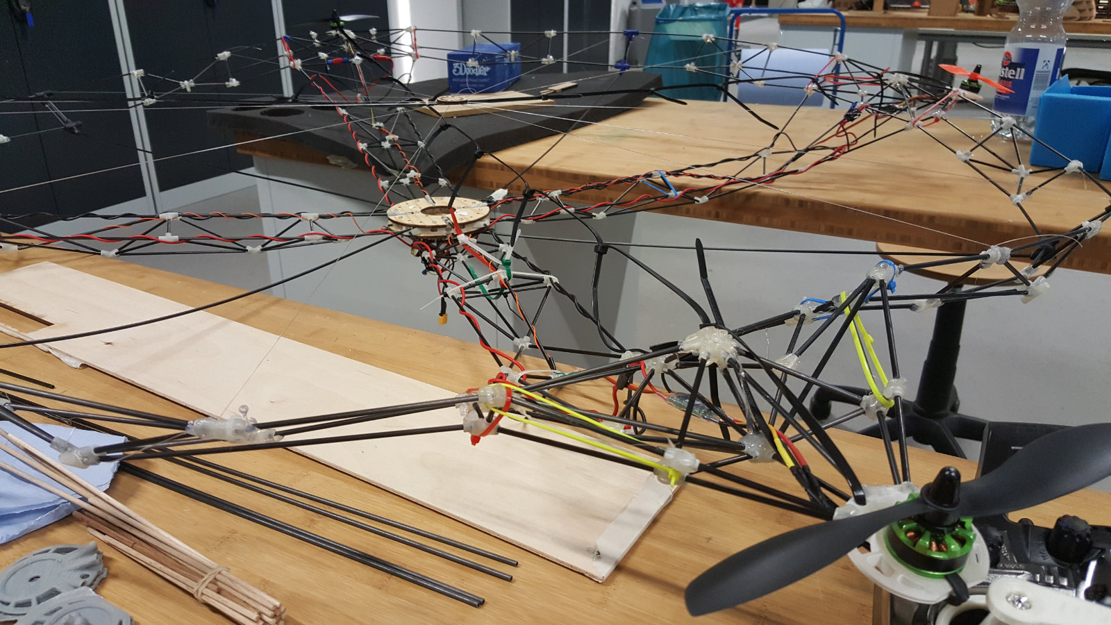
So I ended with a so called spaceframe structure - depending on the material that is used it can be not only lighter than comparable objects also it can be stronger or stiffer than those. My idea to use a spaceframe structure was inspired from motorsports and aeronautics as well as architecture object. I have also two buildings in my neighborhood whose picture I also included. They are a nice example of a spaceframe. And then I also got somehow inspired by nature for the Helium vessel - the skeleton of a sea urchin
Next I did some research to find out if something similar is done before. I found some reports about airships and airship technology but nothing close to my idea. Somebody said to me "Ah you want to make a Blimp?", that is actually somehow a modern kind of an airship. And my design can can be easily mistaken as a blimp but unlike that my hybridcopter will be capable to fly even without the helium vessel. And than I found by accident a short video clip from the research division of FESTO Tools, a german manufacturer of high quality professional tools. They made a vessel filled with Helium and a ringstructure with a couple of rotors to control the ballon-drone. But because of its design, a 1 cubicmeter big sphere it can only be used indoors. Outdoors it would become uncontrollable because of the wind load.
Factor wind load - to minimize the wind load - was one of the reasons that I took in account when I decided to go for a space frame structure - this factor also influenced the shape of the Helium vessel. I decided to design an elipsoid shaped donut. It gives me by a certain size enough volume so that the impetus of the helium will have an effect to my drone. And the "donut hole" in the center I wanted to use for a central housing that will contain the electronics and batteries. And it gives me also the opportunity to keep the center of main mass/weight in the center of the copter and below the motors/props.
I prefer a higher airtime than topspeed. This would be more useful for Aerial photography or for example during an exhibition a indoor flight.
The main thought was to "marry" a multicopter (drone) with an Airship (Heliumvessel) in a manner that looked cool and functional. As I am a designer by profession it is always a natural automatism that my work has to "look" good in different meanings. So instead of taking a standard drone frame and mounting just a ballon filled with helium to it - I sat down and made my mind up how to design a new hybridcopter that meet my needs.
So I ended with a so called spaceframe structure - depending on the material that is used it can be not only lighter than comparable objects also it can be stronger or stiffer than those. My idea to use a spaceframe structure was inspired from motorsports and aeronautics as well as architecture object. I have also two buildings in my neighborhood whose picture I also included. They are a nice example of a spaceframe. And then I also got somehow inspired by nature for the Helium vessel - the skeleton of a sea urchin
Next I did some research to find out if something similar is done before. I found some reports about airships and airship technology but nothing close to my idea. Somebody said to me "Ah you want to make a Blimp?", that is actually somehow a modern kind of an airship. And my design can can be easily mistaken as a blimp but unlike that my hybridcopter will be capable to fly even without the helium vessel. And than I found by accident a short video clip from the research division of FESTO Tools, a german manufacturer of high quality professional tools. They made a vessel filled with Helium and a ringstructure with a couple of rotors to control the ballon-drone. But because of its design, a 1 cubicmeter big sphere it can only be used indoors. Outdoors it would become uncontrollable because of the wind load.
Factor wind load - to minimize the wind load - was one of the reasons that I took in account when I decided to go for a space frame structure - this factor also influenced the shape of the Helium vessel. I decided to design an elipsoid shaped donut. It gives me by a certain size enough volume so that the impetus of the helium will have an effect to my drone. And the "donut hole" in the center I wanted to use for a central housing that will contain the electronics and batteries. And it gives me also the opportunity to keep the center of main mass/weight in the center of the copter and below the motors/props.
based on my ideas & thoughts these are the specifications for my final project:
...my very first thoughts...
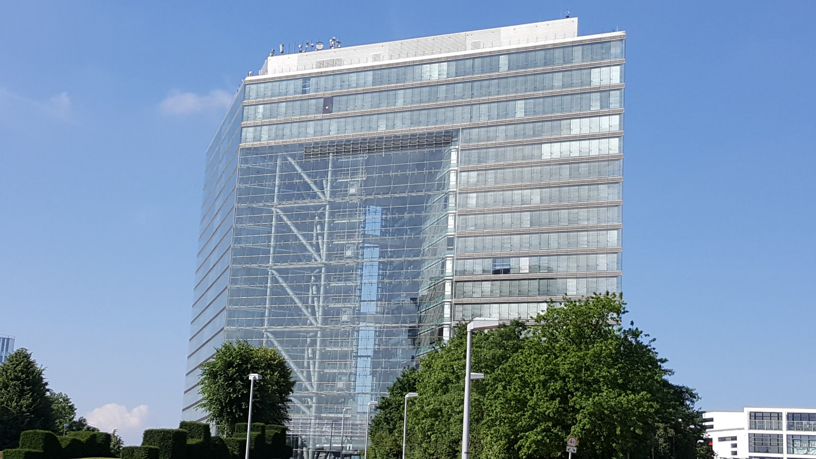
spaceframe XXL Inspirations
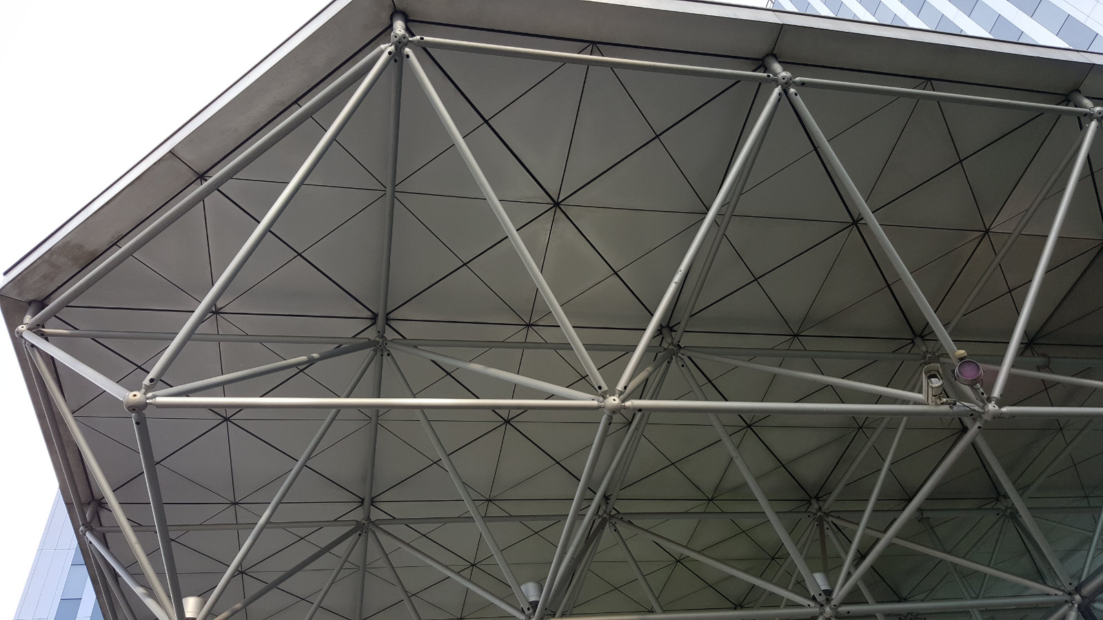
another spaceframe Inspiration
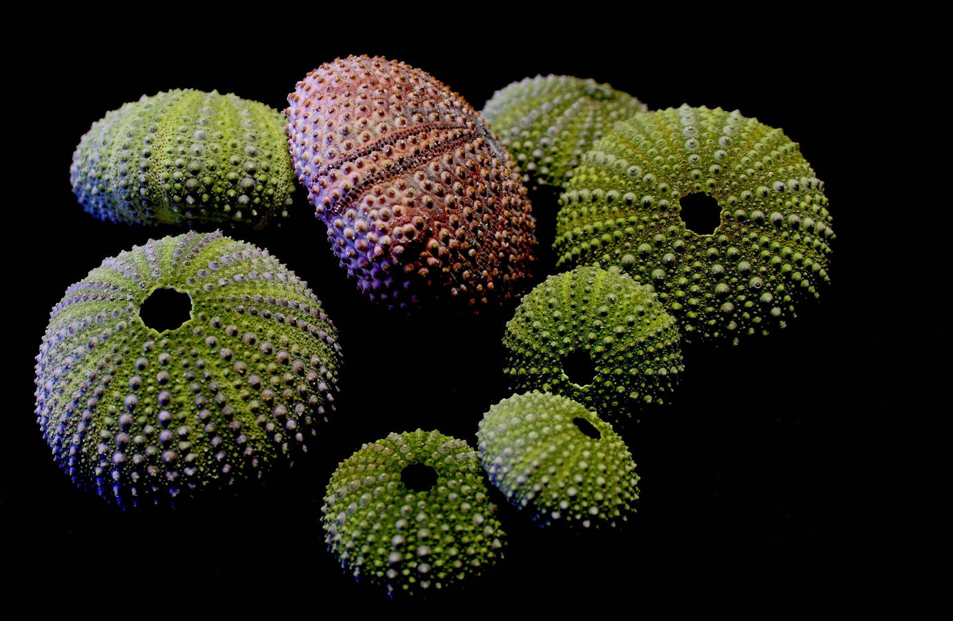
My Inspiration for the shape of the HE-Vessel
Return to Index
CAD design
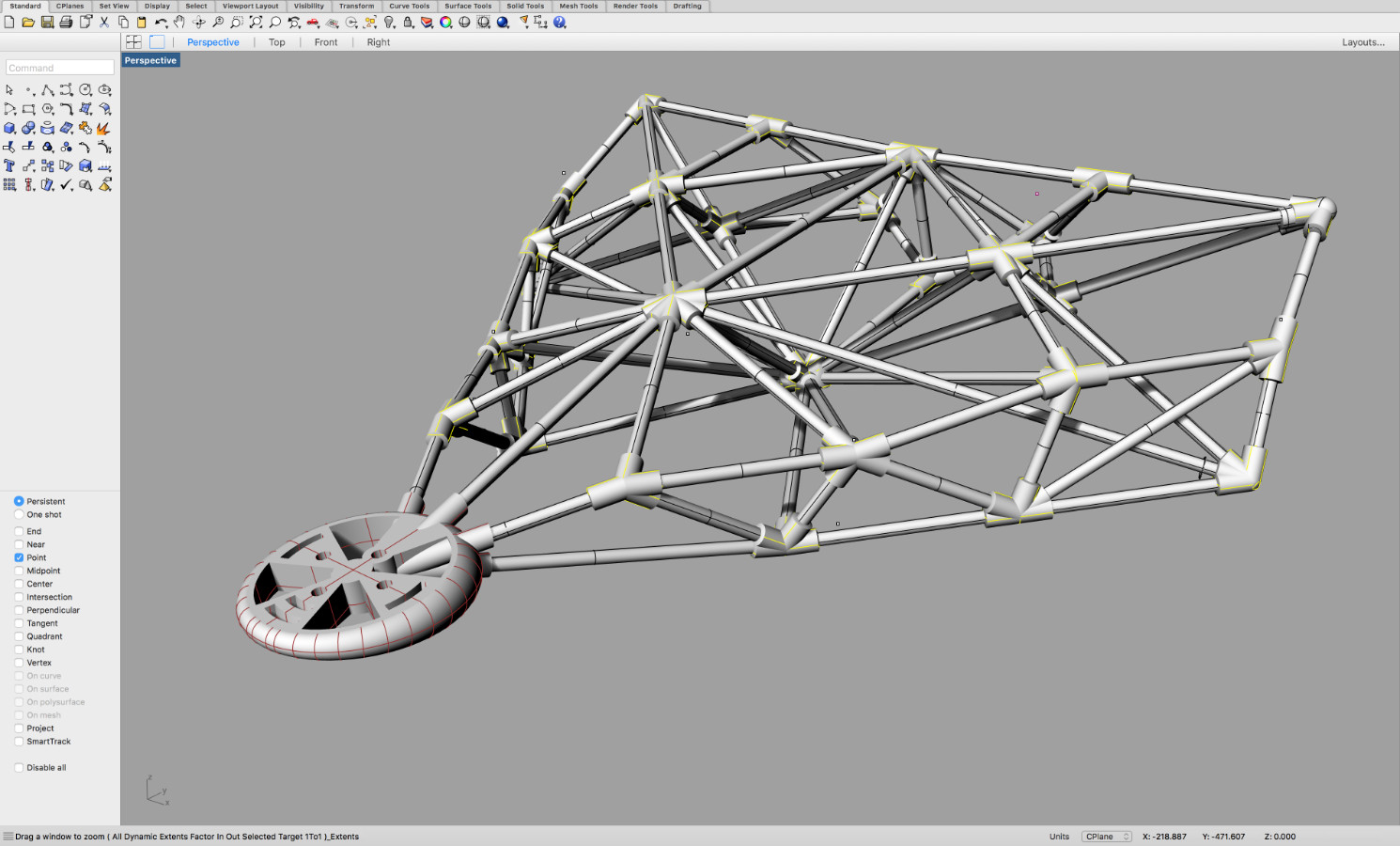
I began my design in Rhino because I'm more familiar with its workflow. As reference object I made first as a placeholder the elipsoid that supposed to be the helium filled vessel that way I had some reference about the space and distances within the structure. And then I began to design around this placeholder the structure. I always start with plain lines and curves, and I'm changing them until I'm satisfied. Then I added points where the lines/curves end or intersect with other lines/curves so that later I could snap easily at those points for any further designs. That way I won't get distracted by any volumeshapes.
Some of these intersection points became later the center points of my joints, also I used them for designing the single space frame beams. And because I planned to design my structure on symmetrical principals, only one half were created and then mirrored - so I made sure that the part that I designed this way was absolutely symmetrical. (by the way it's also a speed factor)
Finally when the part was complete I arranged it around the virtual center point of the vessel/placeholder with the function polar array as many times It was needed for a full rotation (360 degree).

from scribble to the first sketch in Rhino...

another view - for the arm structure

trying to get some symmetry in the structure

the focus on the motor suspension...

nearly final stage...
rendered view of the suspension
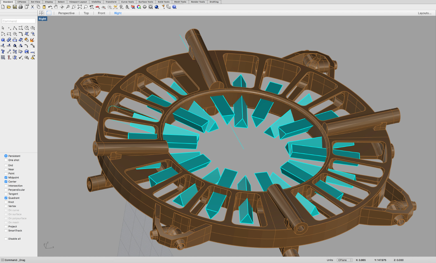
the head plate
Return to Index
prototyping & manufacturing
Since I tried out all the different 3D printers (week #5 3D scanning & printing ) in our FabLab here in Kamp Lintfort, I was eager to use the Projet3500HDMax for my joints. It is fast from high quality and very precise. To print the full set of joints it took me about 7 hours and another 3 - 4 hours melting and cleaning the support wax material from the prints. At first I was very satisfied with the results - but soon I was taught a lesson. The stability for this purpose was not enough, so i was forced to reprint nearly all the joints in ABS and PLA.
But before that happend I built a prototype with benchwood rods and then a second one with carbon fiber tubes.
I wanted to use some composites (week #14 composites ) of glass fiber fabric and epoxy, for the support structure that I planned to make and a couple of moduls that I will either cut with the laser (week #3 computer-controlled cutting ) or with the cnc milling machine(week #7 computer-controlled machining ) . If I would have more time I would maybe try to produce the spaceframe joints with molding and casting (week #12 molding & casting ) - but because of time they will be 3D printed.
Of course some components (motors and rotors) and materials (Mylar foil) I had to buy and the costs herefor were between € 90,- for the motors/rotors and ca. € 45,- for the Mylar foil. For the Carbon rods I found a reliable source, a company spezialised in composite materials and tools - where I paid 1,80 Euro per rod/meter.
I am going to use nearly all processes we learned during our past assignments - just the molding and casting and maybe the cnc milling I will skip. I'm going to make a microcontrollerboard based on Daniele Ingrassias SATSHAKIT with some modifications (week #10 Output devices ) for my needs also the programming of it.
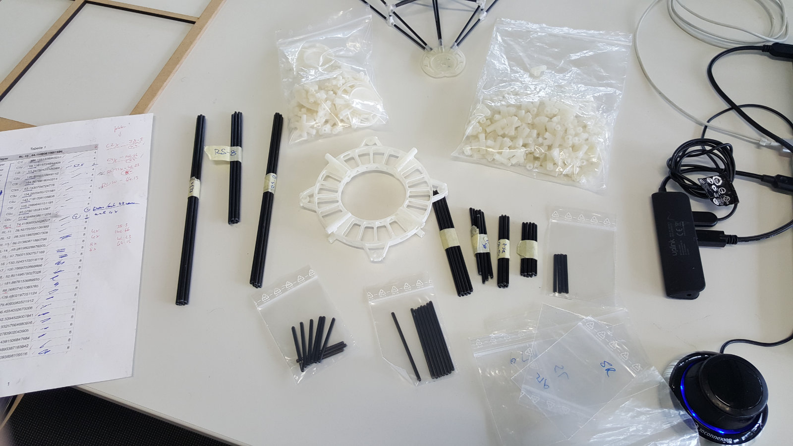
After the cad work was done I thought about the materials I wanted to use for my hybrid drone. I did some research and price comparison and then I ordered 50 rods of carbone tubes in 3 mm diameter, 10 meters of a mylar film for the vessel, the motors and the rotors. I will list my sources where I got my material from in the donwload section at the end of this page.
I exported all the lengths from my cad design to a csv table. this is a handy function in Rhino. It saved me some valuable time. I'm used to name all my parts within a design so that I can easily identify or search for each one just in case. Than I printed a rendered view of the spaceframe to to use this as a quick setup manual. I numbered each joint and each frame beam begining from the end of the structure going inwards. Like this: C01-u for the first upper center beam, 2R-l for the second lower on the right and so on... - This is very helpfull if you have a number of similar looking parts that have to be mounted.


But before that happend I built a prototype with benchwood rods and then a second one with carbon fiber tubes.
I wanted to use some composites (week #14 composites ) of glass fiber fabric and epoxy, for the support structure that I planned to make and a couple of moduls that I will either cut with the laser (week #3 computer-controlled cutting ) or with the cnc milling machine(week #7 computer-controlled machining ) . If I would have more time I would maybe try to produce the spaceframe joints with molding and casting (week #12 molding & casting ) - but because of time they will be 3D printed.
Of course some components (motors and rotors) and materials (Mylar foil) I had to buy and the costs herefor were between € 90,- for the motors/rotors and ca. € 45,- for the Mylar foil. For the Carbon rods I found a reliable source, a company spezialised in composite materials and tools - where I paid 1,80 Euro per rod/meter.
I am going to use nearly all processes we learned during our past assignments - just the molding and casting and maybe the cnc milling I will skip. I'm going to make a microcontrollerboard based on Daniele Ingrassias SATSHAKIT with some modifications (week #10 Output devices ) for my needs also the programming of it.
After the cad work was done I thought about the materials I wanted to use for my hybrid drone. I did some research and price comparison and then I ordered 50 rods of carbone tubes in 3 mm diameter, 10 meters of a mylar film for the vessel, the motors and the rotors. I will list my sources where I got my material from in the donwload section at the end of this page.
I exported all the lengths from my cad design to a csv table. this is a handy function in Rhino. It saved me some valuable time. I'm used to name all my parts within a design so that I can easily identify or search for each one just in case. Than I printed a rendered view of the spaceframe to to use this as a quick setup manual. I numbered each joint and each frame beam begining from the end of the structure going inwards. Like this: C01-u for the first upper center beam, 2R-l for the second lower on the right and so on... - This is very helpfull if you have a number of similar looking parts that have to be mounted.
the first 3D print on the Projet3500 HDMax - 9g !
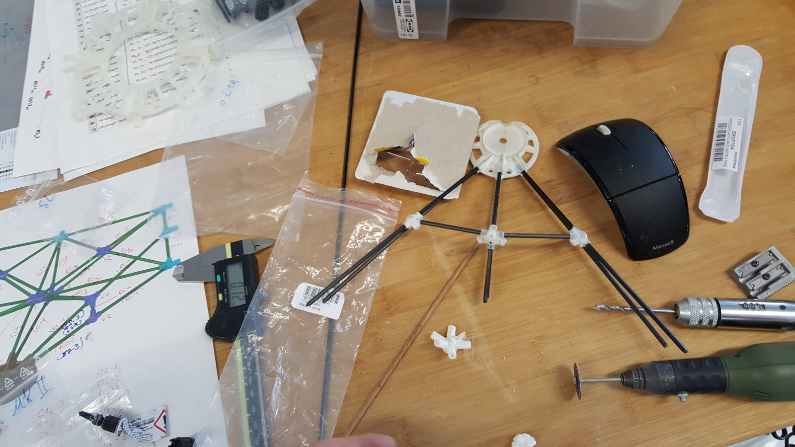
...suspension prototype with benchwood and 3D printed joints...
..in comparison the same with carbon fiber tubes...
...partner view...
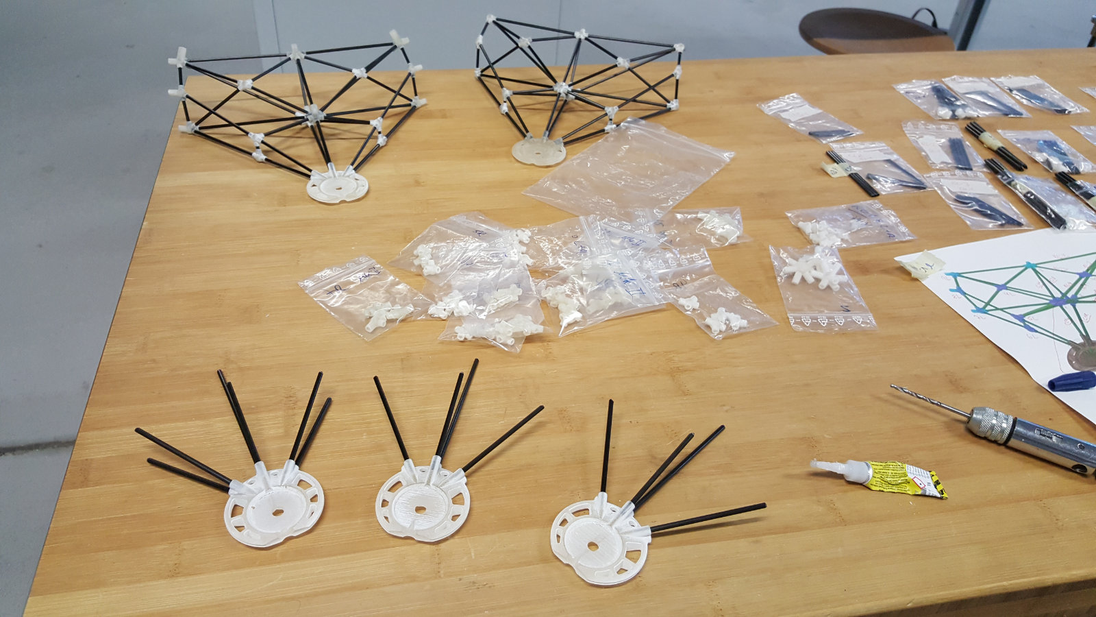
...all the carbon tubes cut to lenght...
...bringing all parts in order...
...ready for the build up process...
...step by step - always checking...
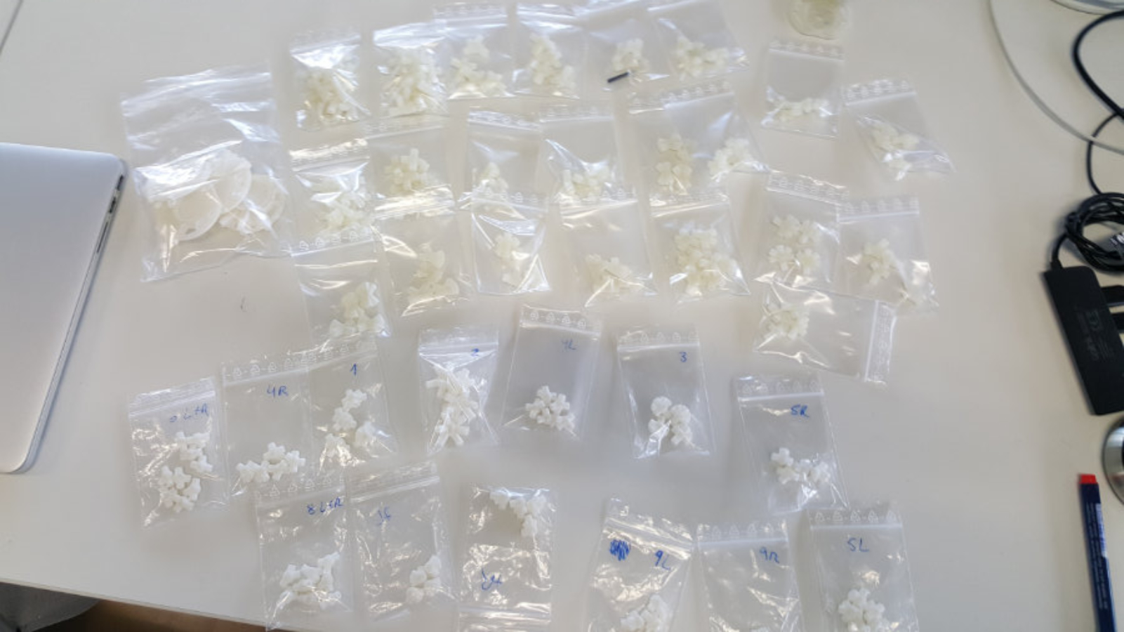
...the sorted joints in bags..
...a view on my workplace..
...everything at the start..
Return to Index
building process
It is crucial to memorise the order of the parts that fit together, because of its structure it will be a hassle or nearly impossible to fit them in a wrong sequence. Carbontubes or rods can be very flexible depending on their length - but the shorter they get, the stiffer they become.
This is something that I forgot in the heat of finishing my final project - and that caused me some trouble and it ended in to have another try of setting up the sequence. My first Prototype was made with benchwood rods in 3mm diameter - this material has the same weight but it is way more flexible than the carbon material - saying so it was no issue to put the bench wood rods in the right position without taking to much care about the order. - Lessons learned !
This is something that I forgot in the heat of finishing my final project - and that caused me some trouble and it ended in to have another try of setting up the sequence. My first Prototype was made with benchwood rods in 3mm diameter - this material has the same weight but it is way more flexible than the carbon material - saying so it was no issue to put the bench wood rods in the right position without taking to much care about the order. - Lessons learned !
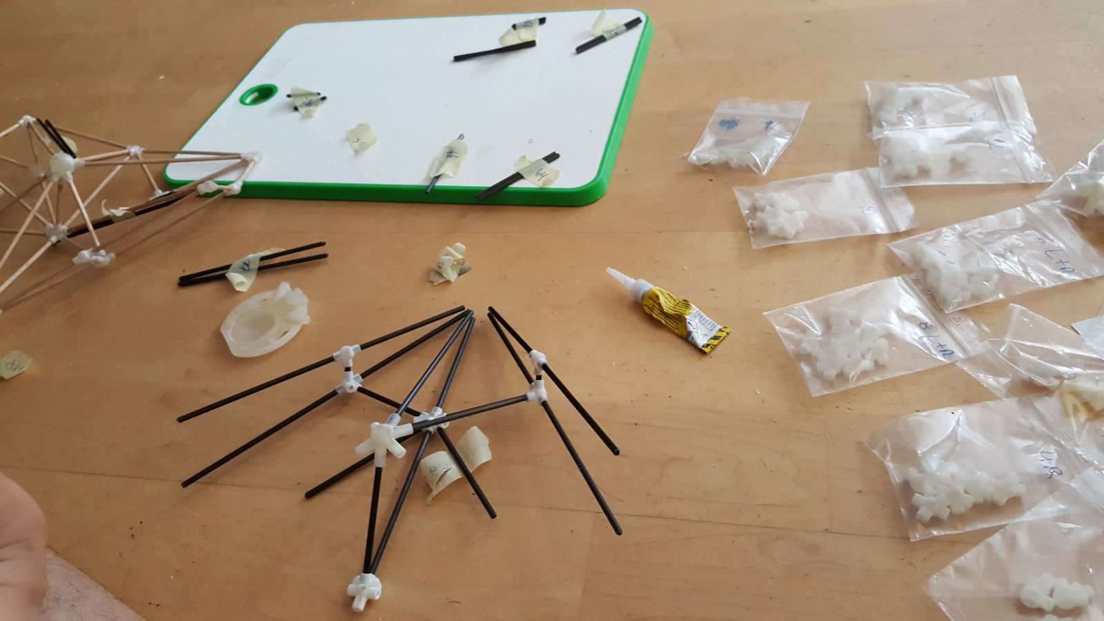
...as mentioned the right order in building teh parts together is cruical...
...one by one - taking a note to memorize the order...

...a very close view of the first finshed suspension...

...another view...
...next one...
Return to Index
spaceframe setup
Actually the section "building process" and the "space frame setup" are some how identical, so all the rules and workflows can be applied here 101 - the difference is in the building process the single parts and elements were put together and in the spaceframe setup those parts were now combined into the complete multicopter frame. Of course there is some difference in handling a part of 10 or 20 cm size or a segment with a lenght of 60 or 70 cm length

...laying out all finished parts...

...coming closer to final structure...

...the center head plate with some addons for the extra rods...

...the motor suspension from the side...

...another view of the motor suspension...
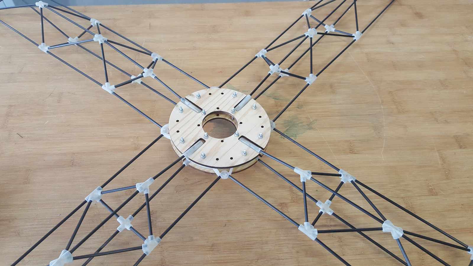
...a top view with fitted head plate...

...the main frame just finished...

...another close view...

...a test setup with benchwood rods...

...a view on the motor bay...

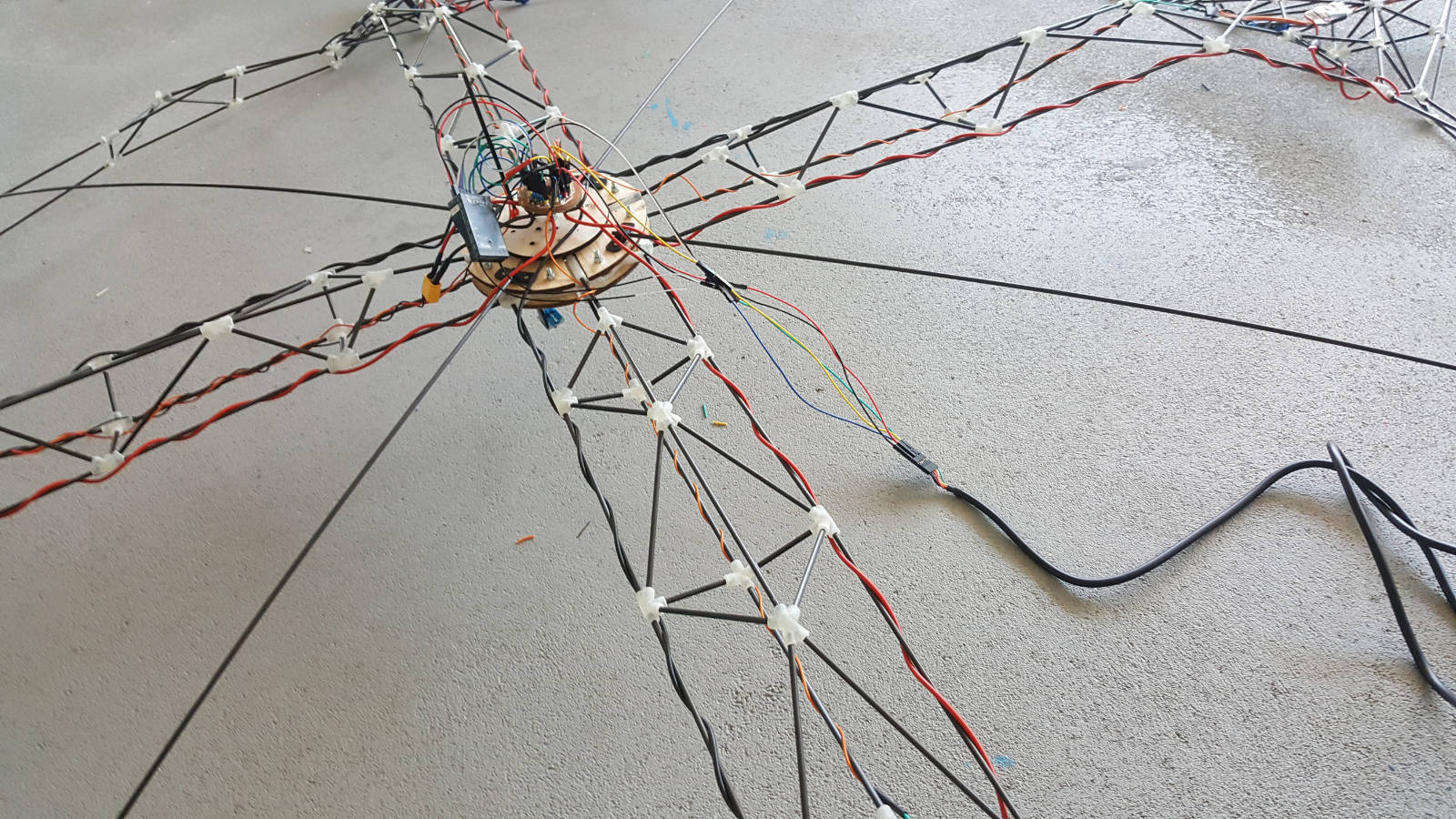
The MK1 structure setup awaiting the electronics
Return to Index
the electronics
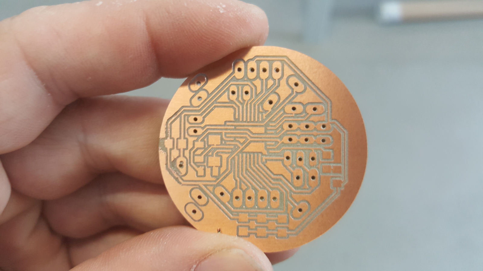
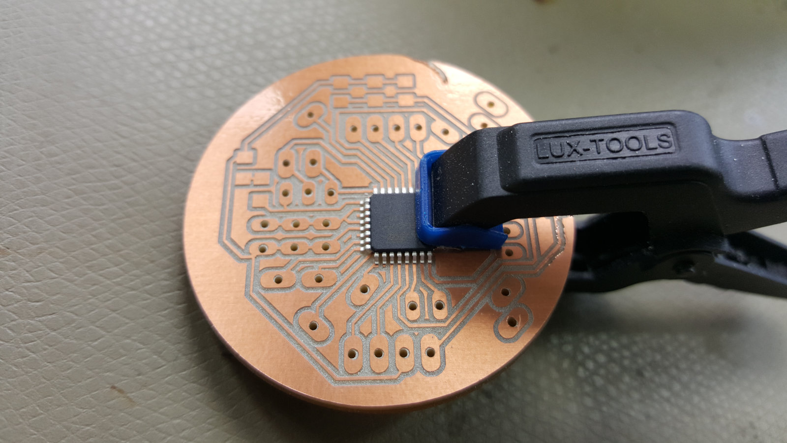
The electronics of the flightcontroller is a section on his own. Based on the SATSHAKIT from Danielle Ingrassia, I modified it to my needs and I did also a redesign of the shape to fit into my copter structure. I made a double-sided board by sticking two single pcbs together and for the IMU (Accelerometer) I made a 'piggyback' board to attach it to the flightcontroller.

...the flightcontroller schematics in EAGLE...

...board layout in EAGLE...

...flight controller traces...

...power board traces...
...pcb cut out...

ready for milling - the setup in fabmoduls
my flightcontroller ready for soldering

the pcb board after finishing the cut out
my way to hold 'things' in place

just in case i made a 'piggyback' pcb for the IMU

my flightcontroller with the IMU on the 'piggyback' pcb
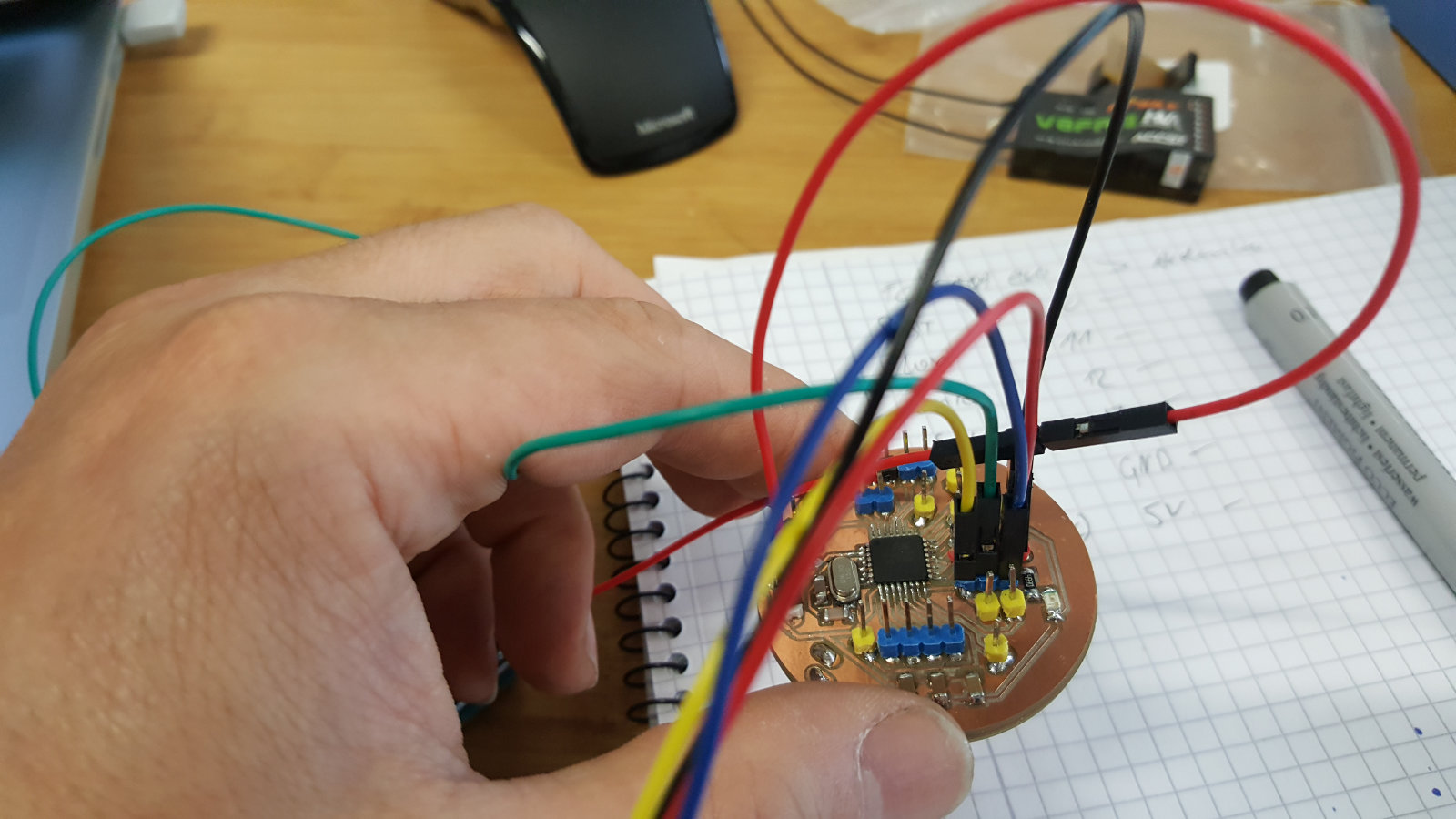
just finished the programming of my flightcontroller
Return to Index
Software & configuration
As software I used the Opensource application MultiWii, that is very powerful but has to be configured well and acurate to make it work. But it is well documented and has a very active community. The modifications I did can be seen on the picture below. It is not only for the flightcontroller software mandatory, also to calibrate the IMU and the motors it is very helpfull.

my copter setup schematics

the interface of the MultiWii software

Here I did the configuration modification for my drone in the MultiWii

...and here...

...and finally here...
Return to Index
Modifications in the software
Below I highlighted the parts that i had to modify for my project
	/**************************    The type of multicopter    ****************************/
    //#define GIMBAL
    //#define BI
    //#define TRI
    //#define QUADP
    #define QUADX //set the configuration for x-shaped multicopter
    //#define Y4
    //#define Y6
    //#define HEX6
    //#define HEX6X
    //#define HEX6H  // New Model
    //#define OCTOX8
    //#define OCTOFLATP
	   //#define DROTEK_10DOF    // Drotek 10DOF with ITG3200, BMA180, HMC5883, BMP085, w or w/o LLC
      //#define DROTEK_10DOF_MS // Drotek 10DOF with ITG3200, BMA180, HMC5883, MS5611, LLC
      //#define DROTEK_6DOFv2   // Drotek 6DOF v2
      //#define DROTEK_6DOF_MPU // Drotek 6DOF with MPU6050
   #define DROTEK_10DOF_MPU // the IMU that is used in the 3rd & 4th run
      //#define MONGOOSE1_0     // mongoose 1.0    http://store.ckdevices.com/
      //#define CRIUS_LITE      // Crius MultiWii Lite
      //#define CRIUS_SE        // Crius MultiWii SE
      //#define CRIUS_SE_v2_0   // Crius MultiWii SE 2.0 with MPU6050, HMC5883 and BMP085
	  //#define MINTHROTTLE 1300 // for Turnigy Plush ESCs 10A
    //#define MINTHROTTLE 1120 // for Super Simple ESCs 10A
    //#define MINTHROTTLE 1064 // special ESC (simonk)
    //#define MINTHROTTLE 1050 // for brushed ESCs like ladybird
    #define MINTHROTTLE 1040 // (*) (**)  //set of the minimum throttle based on them measurement of the motorcontrolers ESC

  /****************************    Motor maxthrottle    *******************************/
    /* this is the maximum value for the ESCs at full power, this value can be increased up to 2000 */
    #define MAXTHROTTLE 1800

  /****************************    Mincommand          *******************************/
    /* this is the value for the ESCs when they are not armed
       in some cases, this value must be lowered down to 900 for some specific ESCs, otherwise they failed to initiate */
    #define MINCOMMAND  1000

  /**********************************  I2C speed for old WMP config (useless config for other sensors)  *************/
    #define I2C_SPEED 100000L     //100kHz normal mode, this value must be used for a genuine WMP
    //#define I2C_SPEED 400000L   //400kHz fast mode, it works only with some WMP clones
Return to Index
preparing for testing
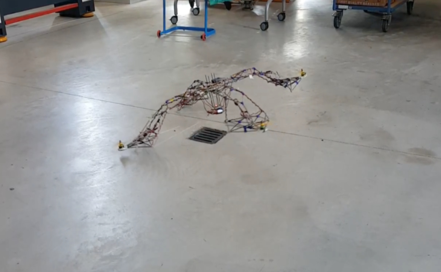
During one of the test flights a part of the arm-ring structure broke of - the joints in that section couldn't take the load peaks that build up during the start. This was the proof of what I already knew, and what's more I realized that also the structure as at the moment designed was to instable to fly.
This was an experience I made during the build-up process due the lack of any previous knowledge with multicopter. And my attitude anyway is that a failure is something good as long we can learn something from it and make it next time better. So I redesigned on the fly the structure - I made it about 30% smaller in diameter - so that it became more stable and compact what I thought would have a positive effect on the flight behavior.
This was an experience I made during the build-up process due the lack of any previous knowledge with multicopter. And my attitude anyway is that a failure is something good as long we can learn something from it and make it next time better. So I redesigned on the fly the structure - I made it about 30% smaller in diameter - so that it became more stable and compact what I thought would have a positive effect on the flight behavior.

checking all the joints and tubes befor going down for tests

the MK1 with some modifications...

The MK1 ready for another testdrive

charging the batteries of the MK1

MK1 closeup

the MK2 ready for the first test run
MK2 indoor liftoff test

MK2 outdoor flight test

reprint of a set joints in ABS...
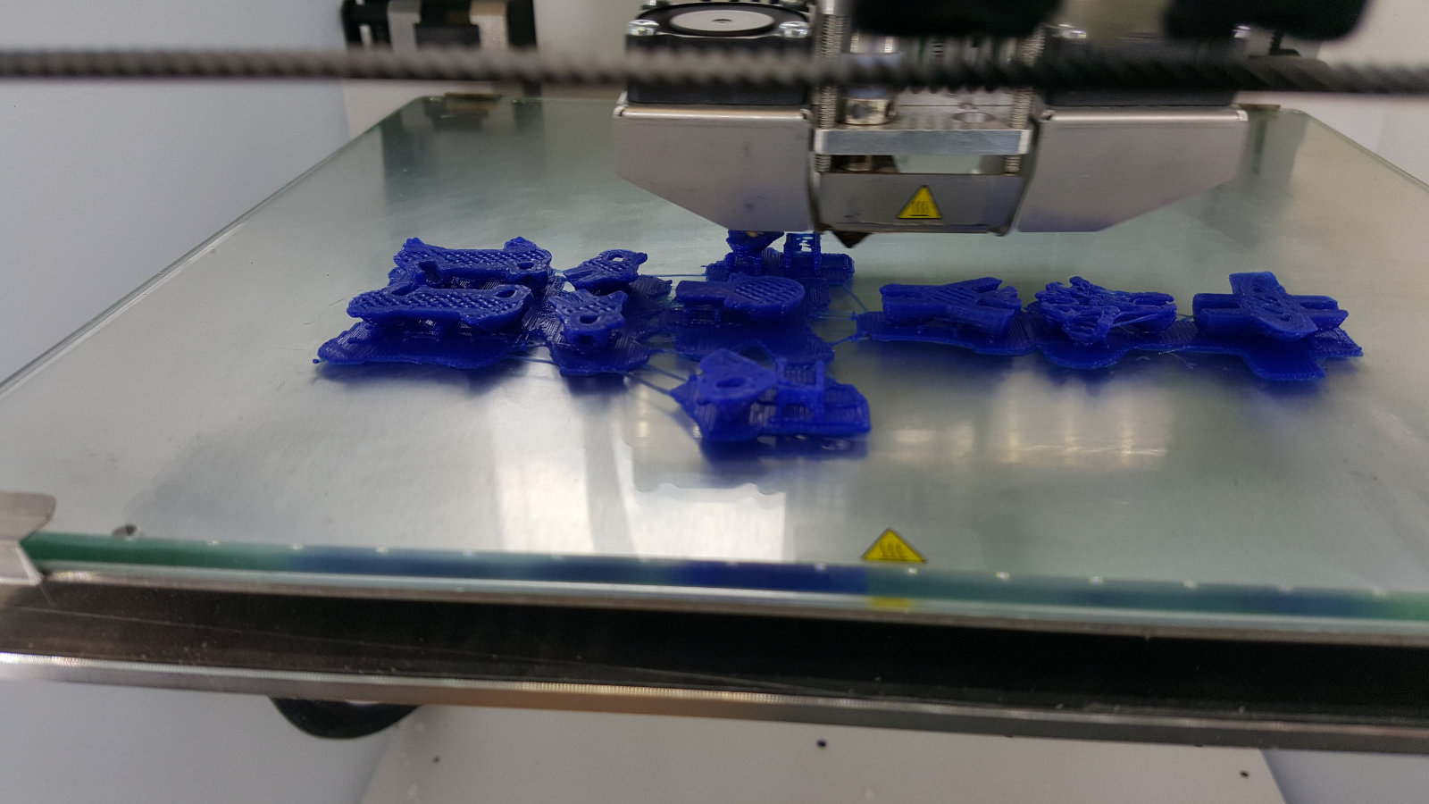
another reprint of a set joints in PLA

a motor suspension with the new joints
Return to Index
Issues
During the building process many issues came up - like the stability of the whole structure. The durability of the joints. Any residue on and in the joints, like leftover wax in the rifle of soem joints. Also finding out in what order the framesections had to be put together. As I collect all issues in this section it can maybe happen that the one or the other problem was mentioned before - I want to apologize for this in advance.

...more to come...
...parts/joints keep breaking when pushed to hard or in a wrong angle...
...looks alright but ...
...in pieces...
For the prototype and the final run 3D printed joints were used and 3mm bench wood rods for the prototype. So far so good, the prototype went so smooth and showed that my intuition for the structure proved to be very reliable. It was quite light and again very stiff. Even with some pressure, that I put on it with my hands didn't broke the structure.
As I found out later, it was the natural flexibility of the wood that prevented the joints to break. And this was also one of the major differences comparing to the carbontubes. A meter of a benchwood rod and a meter of the cfk can be bend nearly for the same degree, but the cfk gets more stiff and more unwillingly to get bend the shorter it becomes, while the benchwood keeps his flexibility to a certain degree.
When I started to rebuild the motor suspension with the carbon fiber rods I quickly realised, that the handling of the cfk differs a lot from the benchwood rods. Thanks to my habbit, always to build first something up without screwing or glueing, I realized that I had to rethink the build up of the structure with the cfk. The order on how the joints and the rods were put togehter was/is crucial
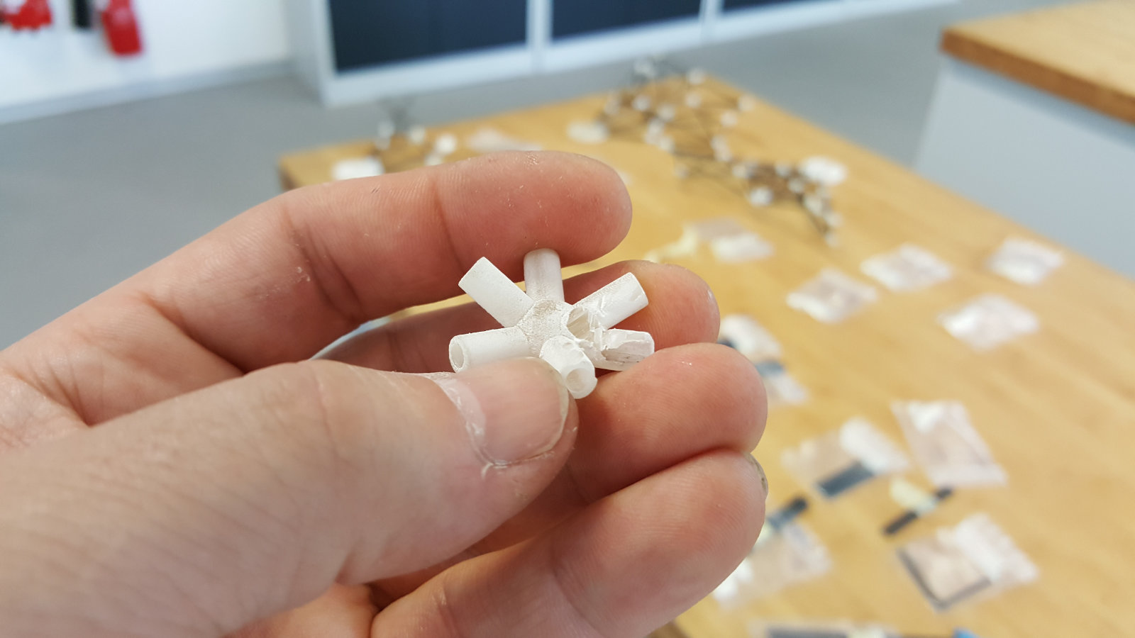
The first set of joints I have printed on a Projet 3500 HD Max. It has an impressive quality and precision and also it is quite fast when it comes to print a lot of parts in the same time. For example it took just 6 to 7 hours to print about 120 joints.
The technology is based on liquid resin that is cured by UV light, and for overhangs and any support structure wax is used. This is a factor that has also to be counted in - to clean the parts - like melting the wax first and cleaning the leftovers in a ultrasonic bath also can take several hours. Unfortunately it didn't worked out perfect for me. Although I did everything as decribed some leftovers still remained - and this caused later a lot of problems within the stability of the structure. The the rods and the joints kept losing connection altough I used superglue to stick them together.
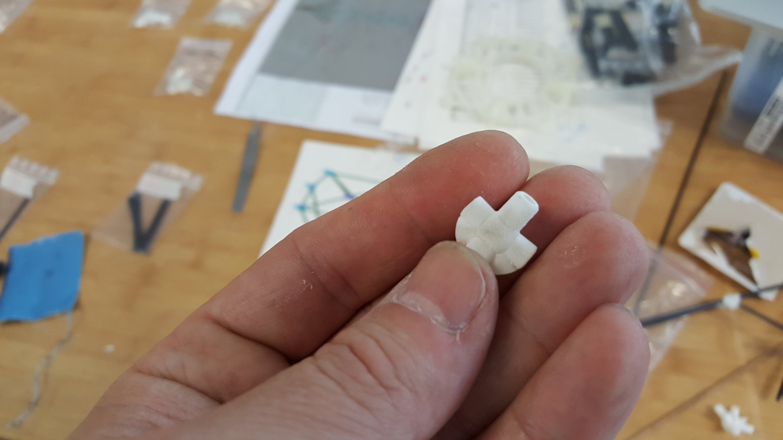
What's more there were in some joints wax left within the rifle, so when I fit them together differences in length appeared and as result the structure wasn't as stable or symmetric as supposed
I ended by printing the joints all over again on a FDM 3D printer in ABS and PLA - the only reason why I used two materials was just because of time. Of course I tried in the meantime somehow to enforce the resin printed joint by covering them by using a hot glue gun - This worked astonishingly good enough to do some test before the new joints were ready for the exchange.
To that stage it was clear that my spaceframe looked different and somehow 'beautiful' as some people said - but that was not the goal - it has to fly!
During one of the test flights a part of the arm-ring structure broke of - the joints in that section couldn't take the load peaks that build up during the start. This was the proof of what I already knew, and what's more I realized that also the structure as at the moment designed was to instable to fly.
This was an experience I made during the build-up process due the lack of any previous knowledge with multicopter. And my attitude anyway is that a failure is something good as long we can learn something from it and make it next time better. So I redesigned on the fly the structure - I made it about 30% smaller in diameter - so that it became more stable and compact what I thought would have a positive effect on the flight behavior
Return to Index
He Vessel
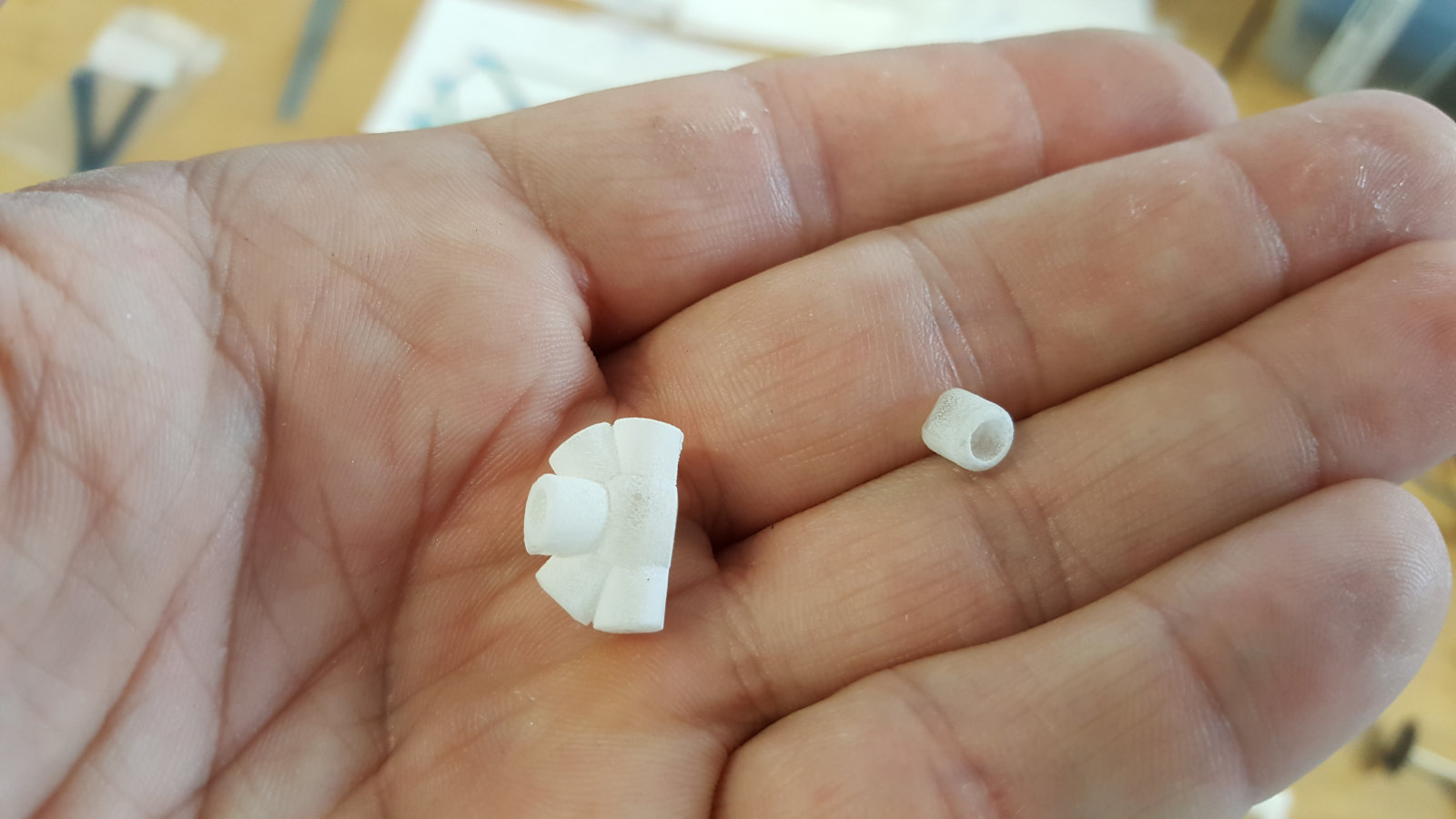
The part with the Helium vessel went out more complicate than expected. To achieve the best possible weight to lifting power ratio, I had to use the lightest material available for helium vessels. A material that is affordable and very light is mylar film, that weights about 16 gramms per square meter. This one has a thickness of round about 24 µm and is very strong. It can be easily cut with a sharp cutter or with the laser cutter. The issues that can affect the workflow is to keep the film absolutely flat for processing it. Because it is so thin it can't be used in the laser cutter without using a vacuum table or any other fixing aid. So a workaround has to be developed in any case.
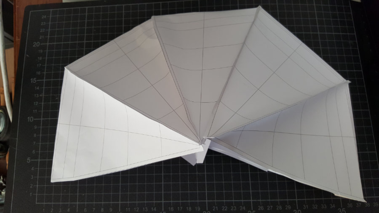
Another point is the choosen shape for my project - an elipsoid shaped donut. To keep the estimated shape, some holding/limiting structure has to build in, because when inflating, the vessel will tend to became a sphere or at least it will not have the estimated shape.
So it took a lot of time to generate usable unfolded segments for cutting. And they need still some rework.
The next problem that came up was to stick the segment parts together - that was not as easy as expected. Using superglue or any gue around the fablab didn't work. Because the surface of the mylar film is so completely clean, the standard glues have no chance to react with the surface to build up any adhesion. After trying a veiw times with different glues, I found out that there is a special 2k glue that is optimised for these kind of sleek surfaces but it is hard to get. Another process for sticking mylar film together is by welding at the seams two parts together either with an solder iron or similar tool. The point here is to find out the right temperature and also the right speed moving the tool along the seams. If it is to hot or the movement to slow, it will just burn and melt through the film. - It was somehow frustrating.
But sometimes you dont't need only power, brain, and coffee - no you need a good portion of coincidence!
When I was at home wandering through our kitchen, i steped over our Vacuum sealing machine - we are using this for sealing processed and unprcessed food for the refridgerator. It has a small vacuum pump and a about 30cm long heat stripe for sealing pp and pe bags. It is adjustable for two timings at a fixed temperature - I gave it a try and it worked perfectly!
Originally I wanted to build up the vessel as one piece, but during the designing and building process, I decided to make it modular, with regarding on the size of the frame, with 4, 6, or more segments. That means a bit more work in making but it will also reduce the danger of a total failure if a leakage happens somehow. The segment would be easily replaceable.
But since I didnt managed to make the a full functional frame structure, the part with the vessel had to be put on hold. But as I will continue with my project here in the FabLab KaLi, it will be part of the next coming spiral development. Any development can be reviewed in future here on my site. My goal is to make it happen - since I'm totally convinced that it will work to my satisfaction.
Finally some technical information about Helium:
Density helium 0.1785 kg / m³, density air 1.225 kg / m³ i.e..
Buoyancy per cubic meter is equal to 1.04 kg
(actually convert in Newton = 1.04 * 9.81)
paper model of the
He-vessel
He-vessel

He-Vessel
paper works folded elements
paper works folded elements

He-Vessel
blueprints for cut
blueprints for cut

He-Vessel
paper works stuck together
paper works stuck together

He-Vessel
paper works stuck together with inner leaf
paper works stuck together with inner leaf
He-Vessel
paper works half setup
paper works half setup

My Vacuum sealer

perfectly welded and sealed...

..it even can take some tension without any problems

checking cable length for the ESC

a different way to prevent the breaking of the PROJET joints

after cutting away the zip ties rest, they had a nice look
a face down setup for the props and motors, also worked
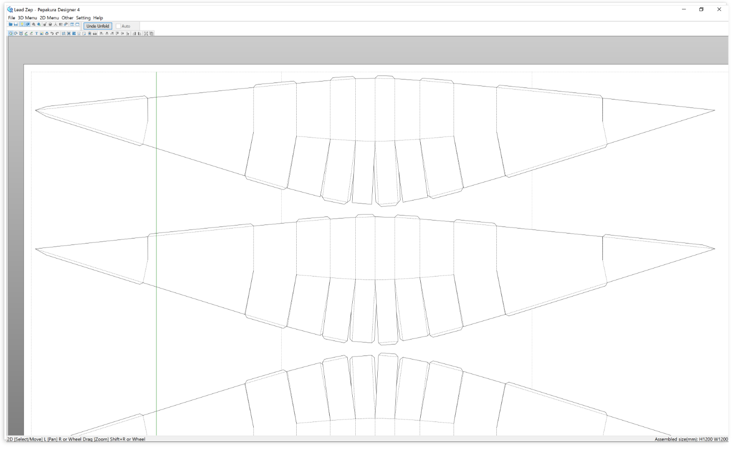
this was the cut layout for the vessel
a close up of the 'big' one
the 'big' one with 120/165cm diameter...

test flight outdoors for the Mk2
Return to Index
Resumee
At the moment my allover resumee is that the weekness and the fail of the first printed joints led to misspent much time for fixing these issues instead of bringing my project to a satisfying end. But the good thing on the other side is that I learned a lot about aerodynamics in the multicopter world, the settings and the configurations that had to be done, the weak points in different electronics, basic safety handlings when working with multicopter ( Thanks Daniele) and a lot of other issues that I didn't know before because I had no experience with Multicopter in any way.
This new knowledge will be integrated as good as possible in my redesign of the structure.
Return to Index
Downloads
Return to Index
My final presentations


This work is licensed under a
Creative Commons
Attribution-NonCommercial-ShareAlike 4.0 International License.