
Week 5. Scanning and printing
During the week I have scanned, designed and printed 3D objects.
Tasks
- Test the design rules for the printer (group work)
- 3D scan an object
- Design and 3D print a small object that could not be made subtractively
Process explanation
Scanning a 3D object
I tried using Photogrammetry form my scanning task trying two different processes: (1) using Sense 3D scanner from 3D systems and (2) taking pictures with my own camera and using Autodesk Remake software
Scanning 3D objects using Sense 3D scanner
Sense 3D scanner (Figure 1) utilizes a technology similar to the first-generation of Microsft Kinect. It is a light device that you hold and move around the object to create the 3D model utilizing software provided by 3D systems. The scanner projects a patterned infrared (IR) beam onto the object from the bottom that is detected by a special cam located in the middle of the device. At the top of the device, there is a normal webcam, which is used to acquire the surface colors of the object.
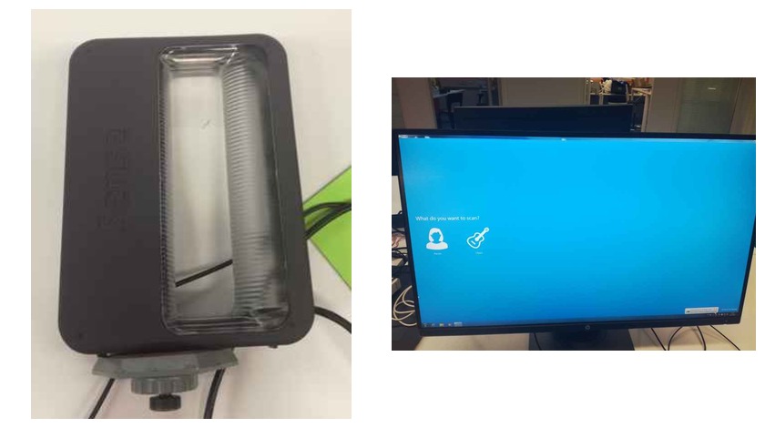
Its usage is very simple utilizing the software provided by the developer company. After installing the software, and connecting the device via USB to the computer, you just need to select the type of object to scan among the following options: small/medium/big object, person's head or person's full body. After pressing the adequate button, the computer's screen will show the object pointing to the scanner. You need to find the adequate distance and angle so the screen shows a green box around the object to scan. After pressing the scan button, you need to slightly turning the scanner (or the object) 360º very slowly. Sometimes, the screen will warn you about missing tracking. In that case, try to get back to the last tracked position. If it is not working you would need to start the tracking again. After scanning the model the software guides you through different post processing tools such as filling the holes, deleting/trimming undesired parts and give a little bit of curve shape to the models.
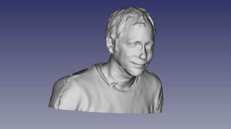
Juha, one of our instructors gave us a short introduction on how to use the software, and he used me as a model. The results of first scanning are shown in Figure 2.
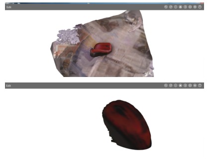
After that I tried my own scanning. I wanted to try a small object, and the one I had right then at my hand was my computer mouse (see Figure 3, left). I decided to check two different strategies:
- Keeping the object static and turning myself with the scanner around it.
- Keeping the scanner static using a tripod and turning the object 360º.
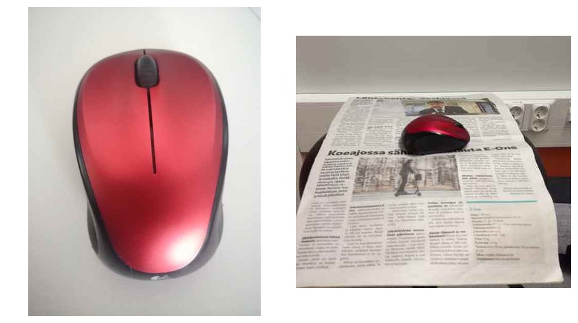
To perform the scanning I prepare the following setup: I placed the object on a black doctor's stool. Since the mouse had a black bottom, I decided to put some white paper on the bottom, so it made better contrast. However, this set up did not work well. It initially found the object OK but when I started scanning it, the software lose tracking very often. Hence, Jani, our instructor, recommend me to place a newspaper sheet on the stool surface. It made the trick and after two or three attempts I managed to get the mouse scanned using the first strategy (turning the scanner around the object very slowly). I had to make some modifications to the lighting condition, because it looks like too much light produce reflection on the mouse which affected the scanner tracking.
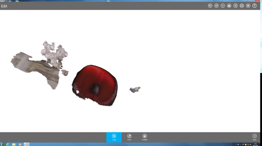
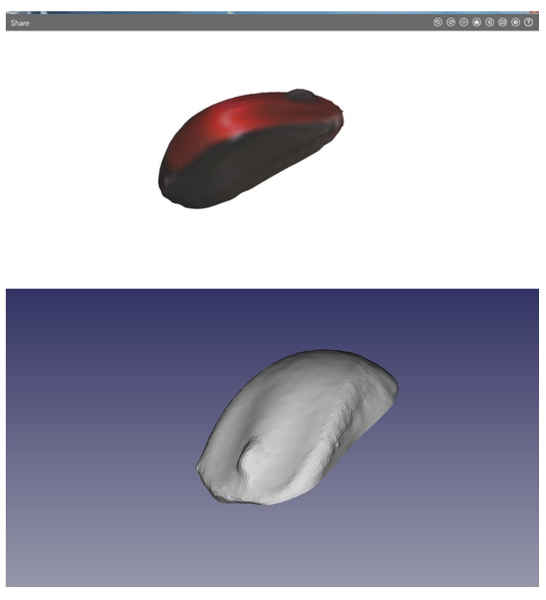
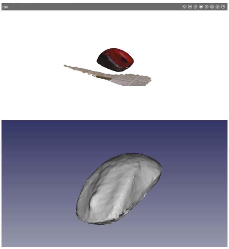
The obtained mouse model had some holes, that were automatically filled by the Sense 3D scanner software. In addition, I had to remove several artifacts using the same software (some of them presented in Figure 4). Pieces of newspaper that appeared attached to the mouse, were removed using the delete and trim tools. After a quick cleaning, and exported to .stl format I got the results shown in Figure 5.
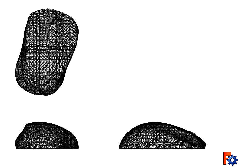
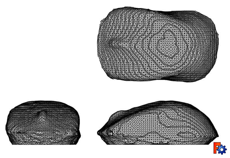
In general the results are not bad. However, after analyzing a bit the .stl file with Freecad, I noticed that the left side was a little bit higher than the second one, so if I have time I will try to fix it with Meshmixer. It is just a matter of removing some material from the bottom that didn't belong to the mouse. Projection are shown in Figure 6. Those files were obtained after transforming the .stl files into Freecad parts.
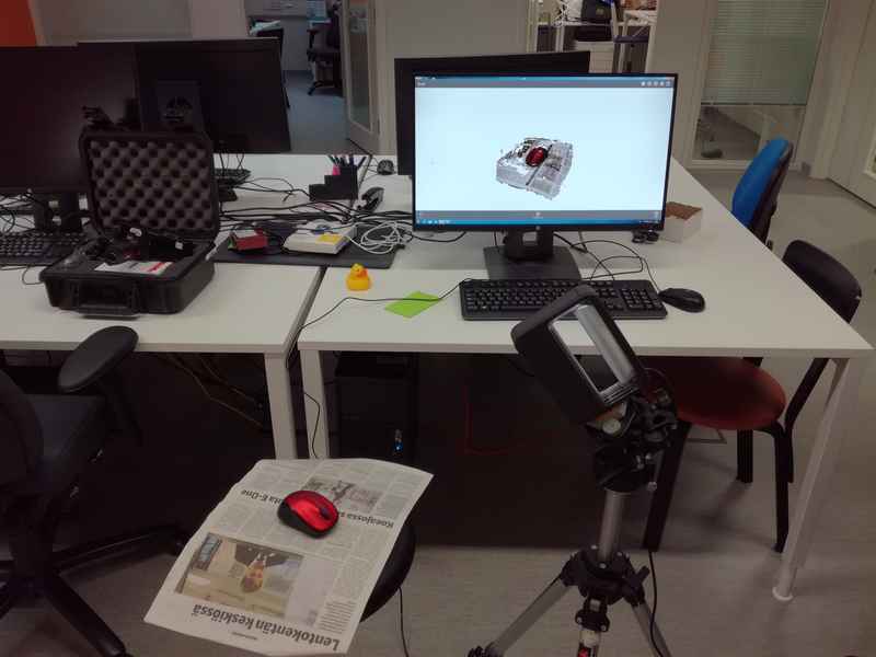
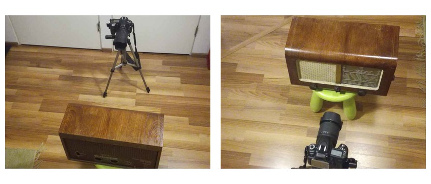
The second approach consisted on fixing the sensor using a tripod (see Figure 7) and rotating slowly the stool. Using this solution took much more time than the previous approach. First of all, the set up took more time. Secondly, I had to find the ideal height and position of the tripod so the object was firstly detected and secondly tracked completely. After several failures attempts (around 5 or 6) and after discarding some models that were not correct (some of them shown in Figure 8), I managed to get a valid model. After cleaning and exporting it to .stl format I got the result shown in Figure 9.
In this case, the final quality of the model looks a little bit better. For instance, the bottom surface was not leaning as it happened in the previous model. I could appreciate a little bit more details in this model (for instance, the curvatures of the clicking buttons could be appreciated better). However, time taken for doing the scanning + cleaning was two or three times bigger than the time taken with the previous solution. Quality is better appreciated using the projections of Figure 9. I obtained this figure transforming the .stl file into a Freecad part.
Scanning 3D objects using a camera and Autodesk Remake software
Taking pictures
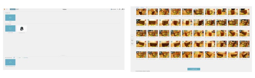
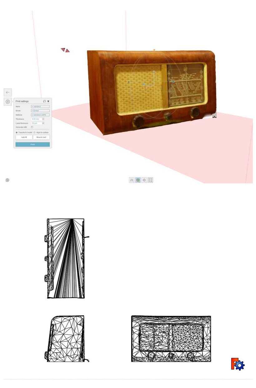
As a second approach I wanted to use my own camera to take the pictures that later will be transformed to 3D using Autodesk Remake software. In this case I decided to 3D scan an antique radio that I have at home (and I am planning to fix in the near future). You can have an idea on how the radio looks like in Figure 11. The first step consist on taking pictures around the object from different heights. I placed the radio on a stool of about 60 cm of height. My strategy was to take a round of picture always from the same height, moving the camera about 15° around the object each shot. When I surrounded the completely the object I took another set of pictures from a higher perspective (in this case taking less pictures than in the previous round) and finally I took another set of pictures from a lower perspective. In total, I took 38 pictures that after sending to Remake software, and process them in Autodesk server returned a failure model (See Figure 12). This is quite likely caused because some of the pictures were not sharp enough. Furthermore, the lighting condition was not the best one. I tried again, this time using the tripod in order to ensure stability of the camera and avoid any undesired movement. Furthermore, I followed a similar approach than previously (taking pictures from 3 different heights). In this case I took a total of 50 pictures (the maximum allowed by Remake service on the cloud). The setup is shown in Figure 11.
Create the .stl model using remake interface
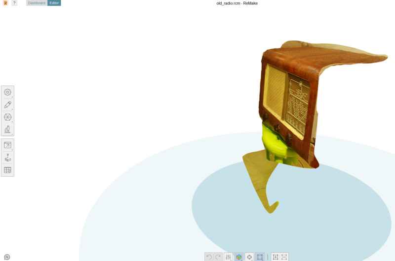
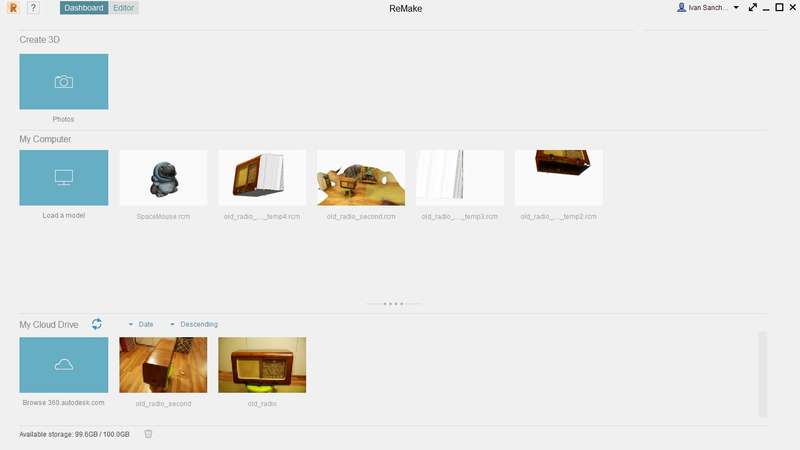
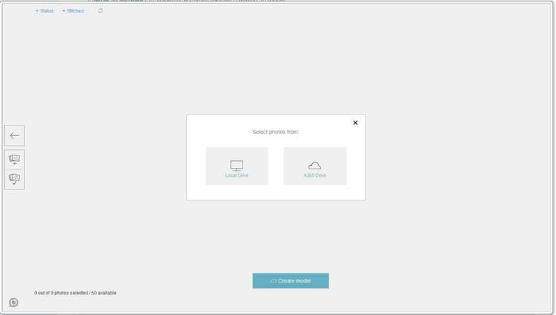
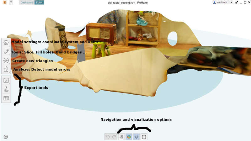
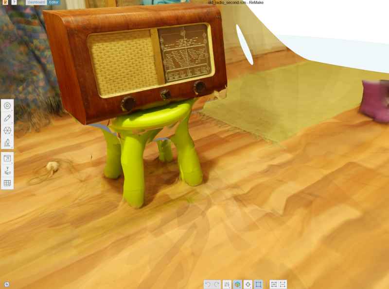
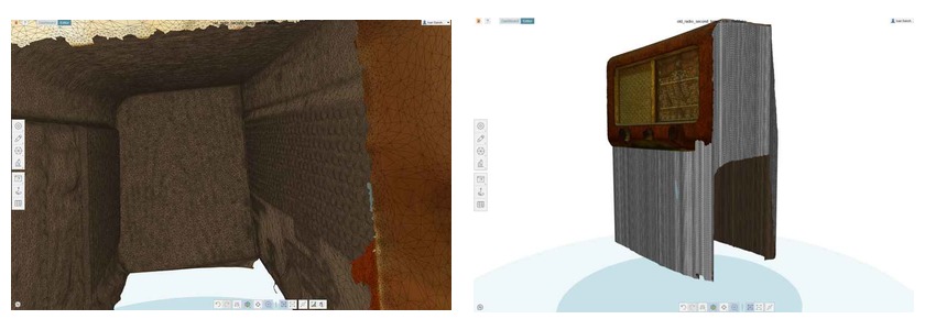
Remake interface to upload and process the pictures is quite intuitive (Figure 13). Just need to select Create 3D Photos, select the photos you can utilize and Remake will automatically send the pictures to the server in order to process them. This time took around 90 minutes to process the whole set of pictures and return the model . The time depends not only on the complexity of the model but also on how busy Autodesk server is at that moment. This time the results were pretty amazing. I got a 3D view not only of the radio, but also partially of the room where I took the pictures (Figure 14). Hence, it was necessary post-process the 3D image in order to isolate the model and fixing some problems in the model.
The process to create the .stl model from the files is as follows:
- Open Remake software.
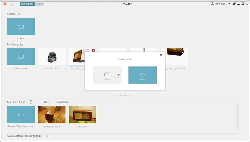
- Press Create 3D > Photos. From the menu select online. You can also process pictures offline, but you should have a really good PC for that: In Autodesk Remake 2017 you need at least: 64GB of RAM, 4GB VRAM NVidia card, 50 GB of free storage space. None of my machines had that huge specifications. I decided to process it in the network (online).
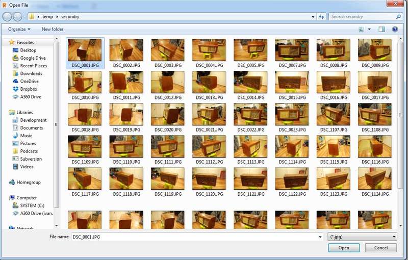
- Select if you are taking the pictures from your own computer or from the Autodesk cloud. I have all of them in my computer. You can only process 50 pictures utilizing the basic account.
- Select the pictures. They should be sharpen pictures, taken at least with an angle of 20 degrees one from each other. Do not forget to do also to include also pictures from the top and for the bottom.
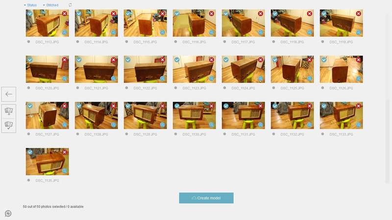
- Confirm by pressing the Create model button
- The pictures are processed in the Autodesk cloud. When they are ready (in my case were around 15 - 20 min) you will receive an email and you can see the final model in the My Cloud drive. You can download it and process it using the Load a model button from the main screen (See Figure 13.1). The interface to post-process the pictures is quite simple. It is shown in Figure 13.6
Post processing, removing unnecessary elements and holes
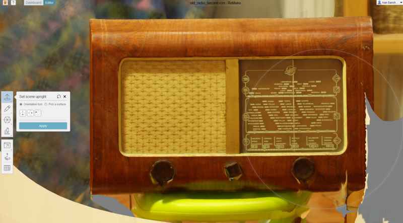
First step needed before starting the post-process itself is telling Remake which are the right angles of the 3D model, that is, which is the correct orientation of the model in the space. This can be done easily with the Set scene upright tool
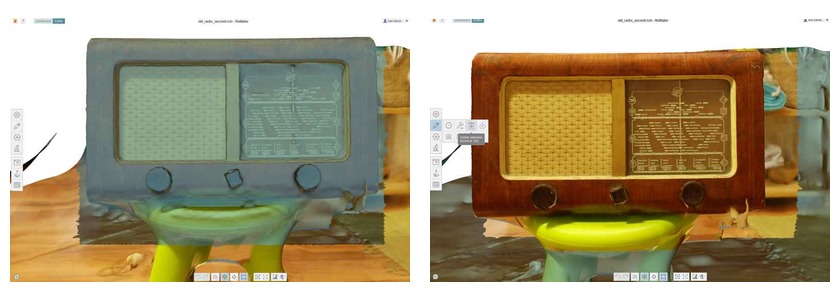
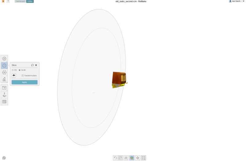
After that I started removing the objects that I was not interested in. First, I utilized the rectangle selection tool to select the radio (easy considering its shape). I inverted the selection and deleted the surroundings objects (Figure 16). I still had to remove the background. To do that I utilized the slice tool creating a plane perpendicular to the bottom and parallel to the rear face of the radio (Figure 17)
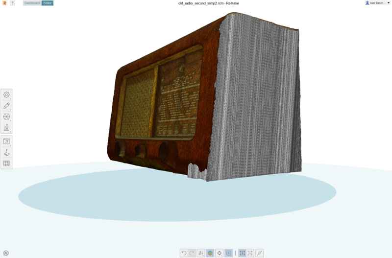
Once I removed all external objects, I had to work a bit with the radio 3D model itself. For instance, one of the side faces was completely inserted in the body of the device (Figure 18). I had to removed the whole face using the Brush selection tool (Figure 19). This tool allows to select a different amount of tiles from the model. You can control the size of the brush using Ctrl + wheel of the mouse. It was a time consuming task, specially, because you had to remove the borders using a very thin brush.
Once the face was completely removed I utilized the extruding tool to generate a new one. The extruder tool takes any OPEN border and extend it in the direction you define. It is necessary to define the extruding offset. As it is shown in Figure 19, the tool generate larger walls than needed. Hence, I had to use again the slice tool again, but using in this case an horizontal plane (Figure 20).
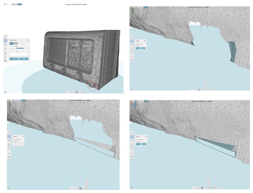
Next I had to fix some imperfections and holes. There were some strange artifacts and protuberances (e.g. Figure 21, top-left) that I had to remove using the sculpt tool. This tool permits pushing or pulling certain areas of the surface in order to make it more uniform. To close the holes, Remake has a hole filler tool. However this tool only works if the whole is totally, closed (I mean, surrounded by other surfaces). This does not happen in the hole that can be seen in Figure 21, top-right. Hence, I had first to create a bridge (bridge tool) between two surfaces. In this case, I choose flat bridge, but you can select a smooth option which tries to imitate the surrounding surfaces. Other holes, were filled in using the hole utility. Finally, I utilized also the hole tool to create the radio's floor, and in that way make a closed model. In this case, I used the flat option, so it created a flat surface.
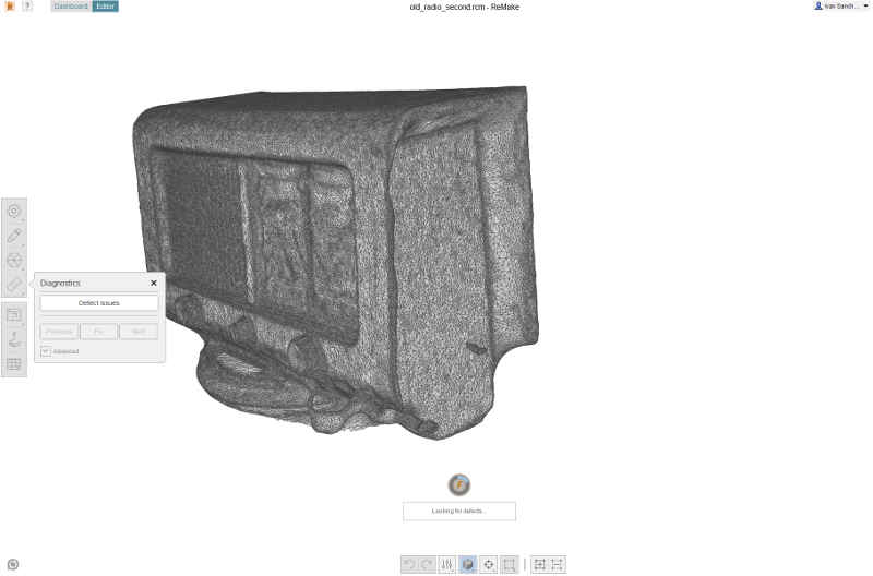
Preparing .stl for printing. Using the diagnostic tool.
Remake's diagnostic's tool check the model looking for particles not attached to the surface, holes and self-intersections. In addition, it can solve the errors automatically just pression one button. In my case, it removed all particles and closed the holes. However, I had to work myself on the self-intersections, removing them using the smoothing tool. Finally, I managed to remove all the errors. Figure 22.
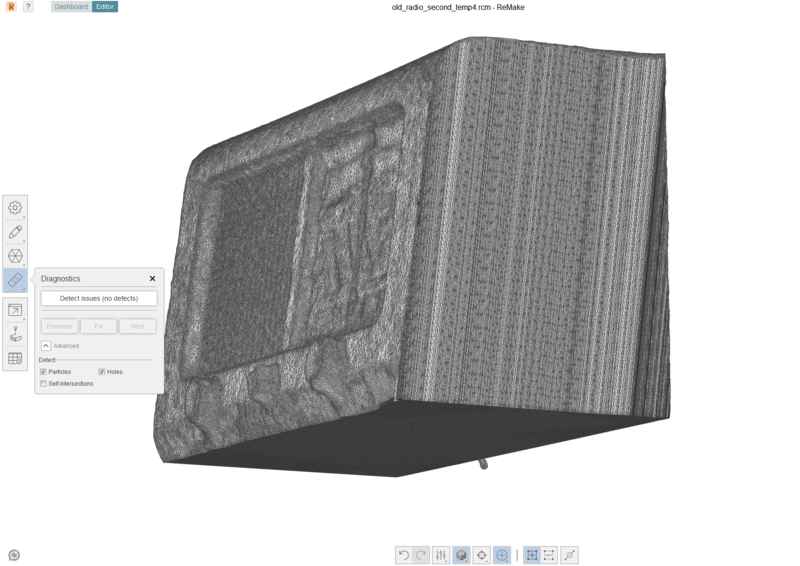
Figure 23 (top) shows the 3D radio model after the diagnostic tool. I exported the model in a .stl file and utilized Freecad to create the projections shown in Figure 23 (bottom). Although, I do not 3D print it, I used Slic3r to check if the model might be printed.
Comparison
All in all, I got a really nice 3D model of the radio. In my opinion, the model is much better than any 3D model that I could have obtained with the Sense 3D scanner. However, taking pictures, processing them, cleaning and fixing problems required much more time (4 ~ 5 more times) than the Sense 3D model. The Sense 3D scanner offers lower quality but permits create models faster. However, it is only usable for small - medium size objects. The quality of the models are much worse than using Remake. In addition, the scanner loose tracking very often and you had to start scanning again. I did not manage to get the scanning from Sense 3D at once. I always had to repeat it.
Modeling and printing a small 3D object
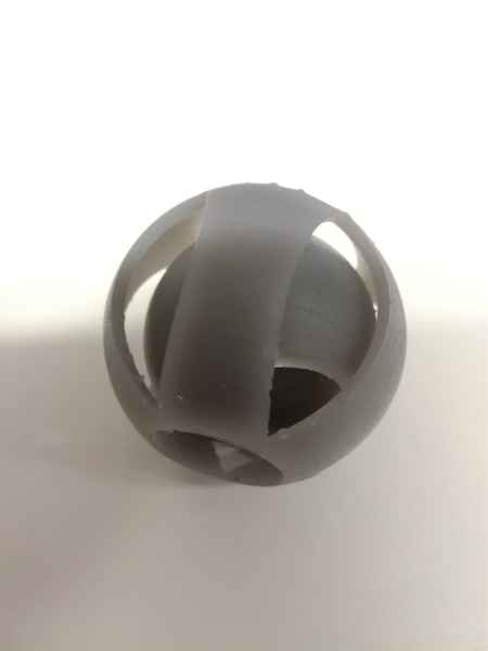
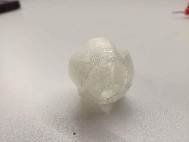
For this task, I planned to have an object inside another, so I can have an object that cannot be obtained using substractive approach. I decided to create a spherical segment containing another spherical segment. The inner sphere should freely move inside the outer one. In order to be able to observe the inner sphere I designed some holes in the outer sphere. The final design can be seen in Figure 24.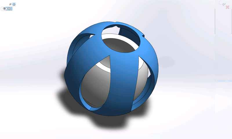
Since in previous weeks I have used Freecad, Fusion 360 and 123D, this time I utilized Solidworks to produce the models. The process was as follows:
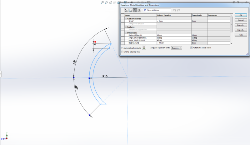
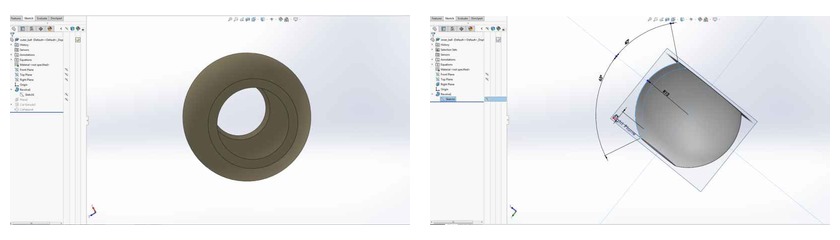
- Create an sketch, and draw a circular segment there. I utilized parameters to define the radius of the external wall (15 mm), the thickness of the material and the angles of the upper and bottom vertex. In order to link dimensions I utilized the Menu > Tools > Equations. This tool provide a table where you can define global variables (e.g. wall thickness) and values of dimensions. The value of a dimension can be a constant or an equation (to link several dimensions together)
- Revolve the sketch using Features > Revolved Boss/Base tool. I had to draw an auxiliar line, perpendicular to the sketch, as a revolution axis. I created the line in the sketch (Y axis) and set the options For construction and Infinite line.. After revolving 360 with no direction (Blind) I obtained the part shown on Figure 26.
- Create the smaller spherical segment. I just saved the part as a new name and modified the dimensions (mainly external radius (10mm) and angles. I guess there should be a better approach, but I did not manage to find the way of cloning / duplicate the part. I will investigate that later.
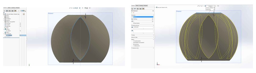
- Add holes in the outer sphere. To do that, I first created a sketch in an auxiliary plane tangent to the sphere surface in the X axis. This plane was created using the Features > Reference Geometry > Plane. I draw a simple figure: 2 circumference arcs that have the same vertex. I left 1mm from top and bottom of the spherical segment for not breaking the spherical face. After that I run the Features > Extruded Cut wizard utilizing the sketch plane I have just created as origin. I set an offset of 10mm. In that way I got one hole (Figure 27, left). For creating the rest of the holes I utilized the Features > Linear Pattern > Circular pattern, taking the previous hole as a pattern. I repeated the holes 5 times with equal spacing (Figure 27, right). Both pieces were ready.
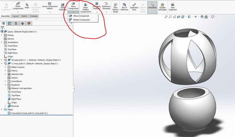
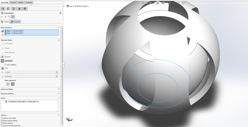
- I created a New assembly and added the two previous parts (Insert components. I had to rotate 180 the inner ball and move the inner sphere inside the outer sphere using the Move component tool (Figure 28). Once inside I created a new Concentric Mate so both spheres share the same axis (Figure 29). I utilized the Physical Dynamics option from the Move Component in order to check that the inner ball could not abandon the outer ball.
- The model is now ready
- Export the model as .stl file. It is important to activate the option: Save all components of the assembly in a single file.
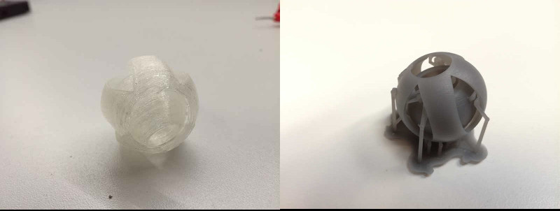
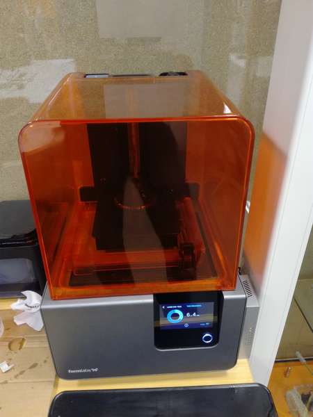
Next step was to print the model. We utilized two different 3D printers: FormLabs Form 2 and LeapFrog Creatr.
Printing in FormLabs Form 2 printer
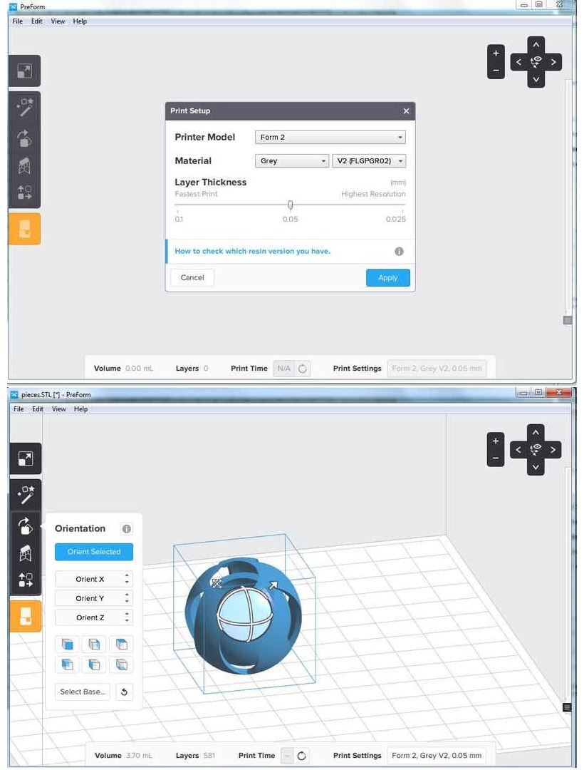
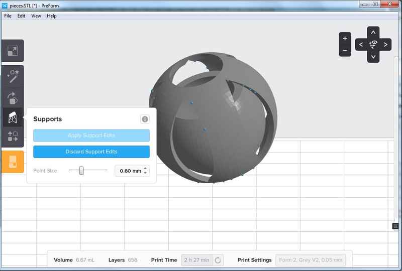
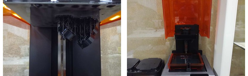
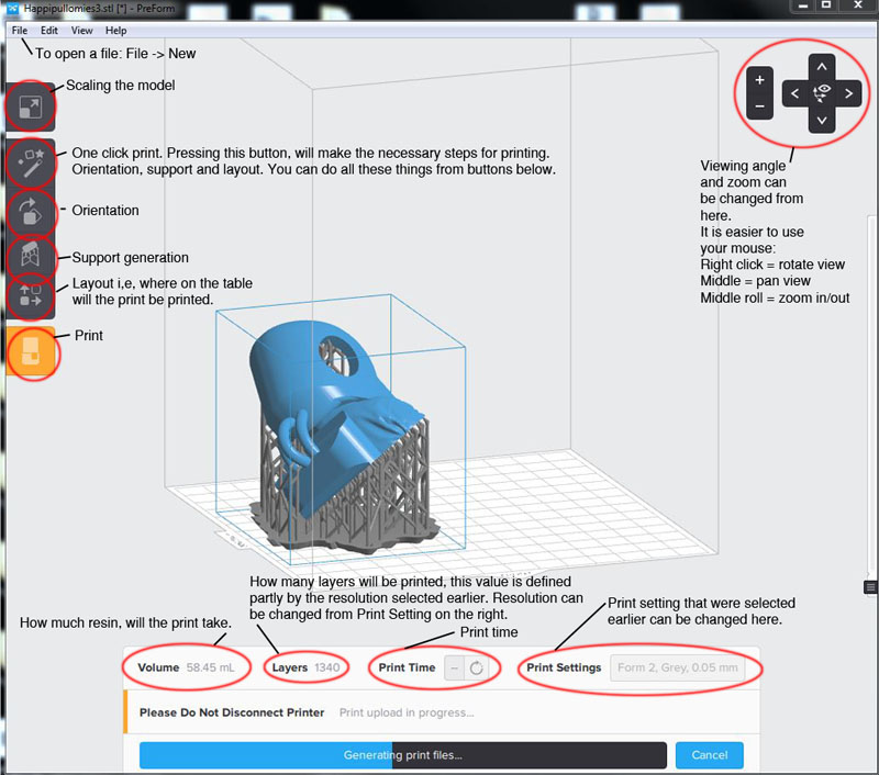
ormLabs Form 2 is a resin printer. More info on in In the Design rules section. This printer came with its own software to set up the files to print. This software do the slicing and calculate the positions of the support material. I utilized the default resolution (0.05mm) for my printing. The UI permits rotate the figure and modify its position on the tray utilizing the button bar on the left (Figure 30).
I utilized the Support tool to automatically create the supports for my print. I had to add more support points because some of the surface areas were marked as red. To add a support point just click on the position you want to apply the support. (Figure 31)
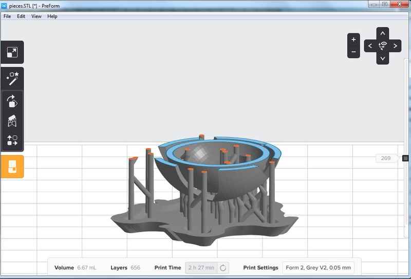
After that I pressed the button Calculate time located at the bottom menu bar. It did the slicing and add the support material (Figure 32). After that I just send it to print and I got the results on Figure 33a and b.
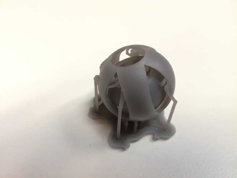
It took some time to remove the whole support material using a plier. Actually, it was really difficult to access some of the support points to be removed. It is really important to take that into consideration when creating the supports in the software. Avoid, very hidden positions for the material.
Operating the FormLabs printer
After sending via Preform software to the printer I had to operate the printer to create the object. The process is as follows:
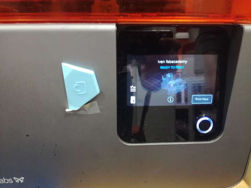
- The formLabs screen shows instructions on how to proceed. The first screen shows "READY TO PRINT" message. Just press the "Print now" button (Figure 33.2). It is important to remember that this printer will print upside down, that is, the bottom of the model will be printed on the top of the printer.
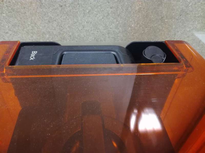
- The printer will check that the amount of resin is enough and that the ventilation cover is open. If there is not enough resin you shoud add more in the adequate compartment. If you forget to open the ventilation tube you should open it (Figure 33.3)
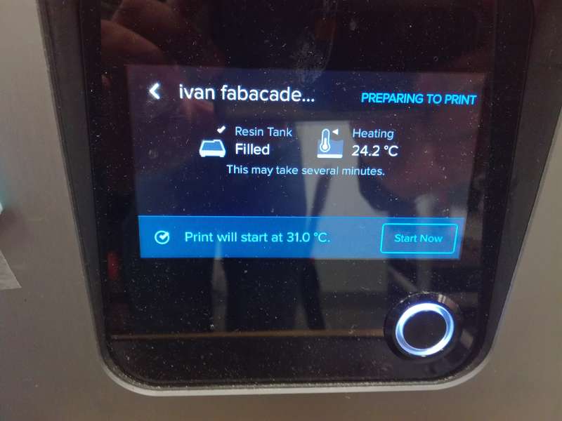
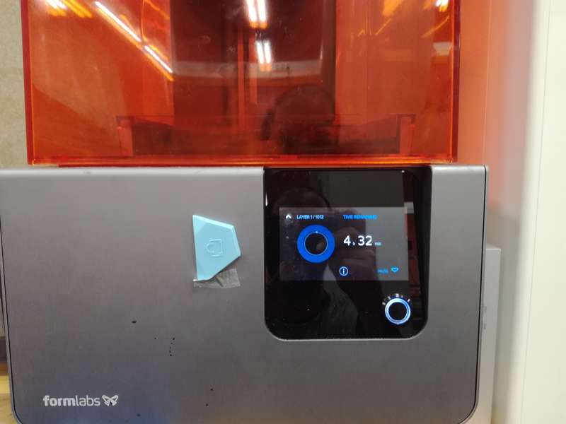
- After the resin tank and the ventilation are OK, the printer will start gaining adequate temperature (Figure 33.4). Then the printer will start printing. The UI will show the remainig time and the status of the current layer (Figure 33.5)
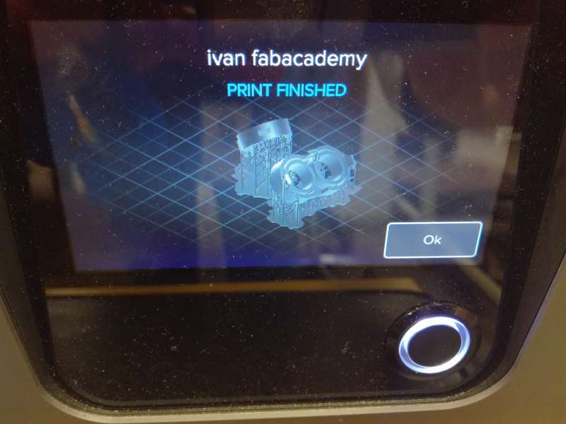
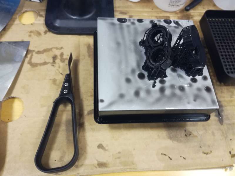
- When the printing is finished the UI will inform about it (Figure 33.6). Then you can open the printer (Figure 33.7) and extract the tray which contains the printed model. To do that, just remove the lock and gently pull it out.
- Once the object is out you need to remove from the tray using a palette knife or similar object.
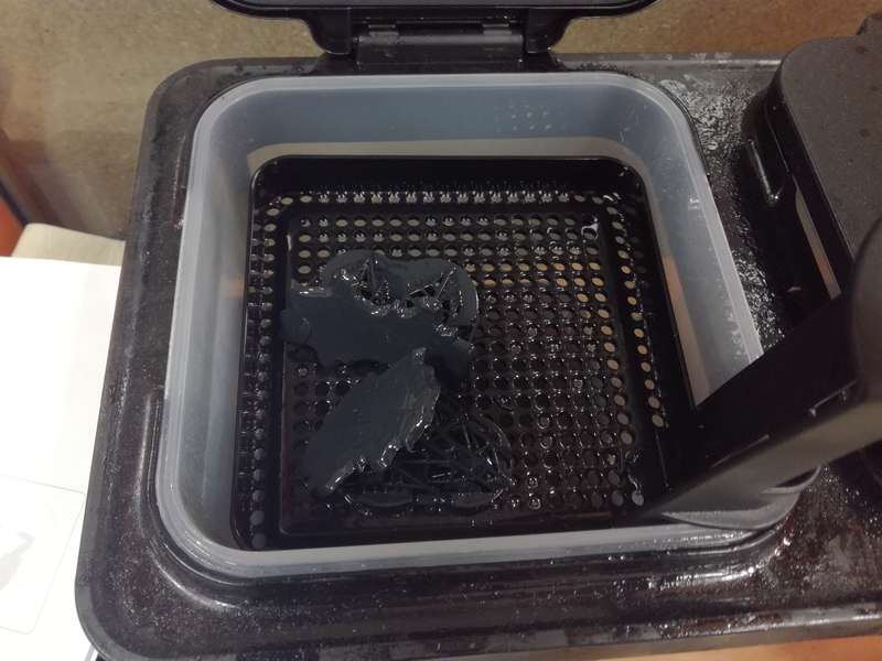
- Next you leave the model in propanol for 20 - 30 minutes. I utilized two different containers and left the model 15 min in each container (Figure 33.9)
- You must clean the tray and all the utilized utensils with propanol. In addition, you must remove all solidified resin from the main tray. To do that, you need to scrape it gently with a palette knife, always in the same direction. All resin stick to the bottom should be removed (Figure 33.10)
-
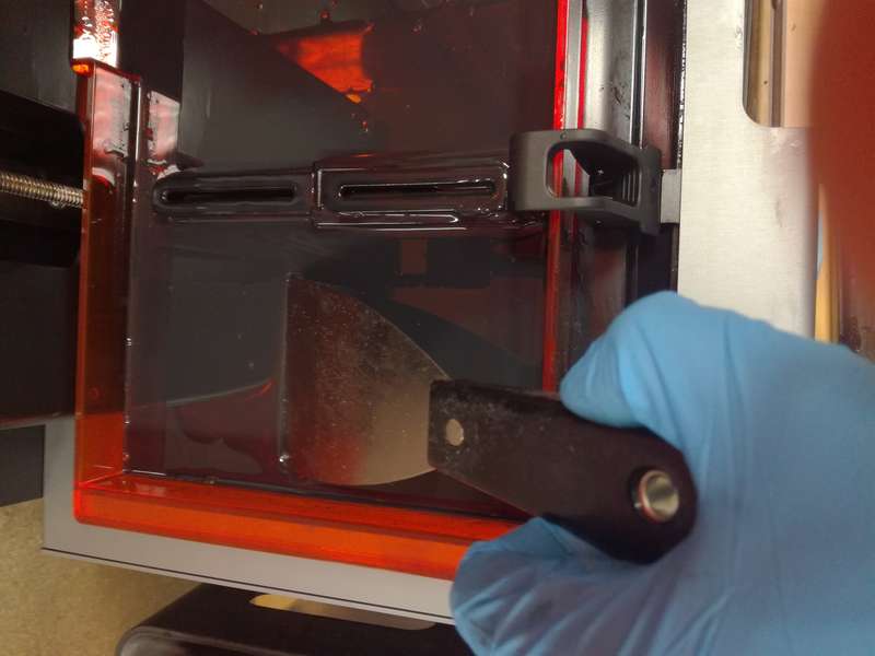 Figure 33.10. Removing remaining solid resin from the tray.
 - Finally, using small pliers you need to remove the support material from the model
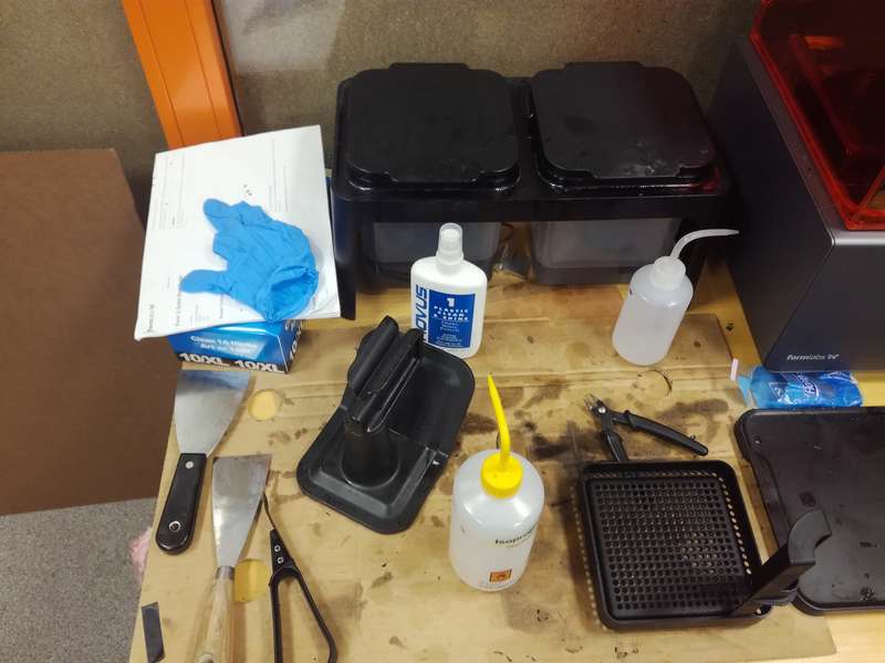
Safety issues
Handling the resin might be dangerous. You must always use gloves and protective glasses when manipulating the printer or removing the models. In addition it is very important to clean all the utilized tools with propanol and leave them dry by themselves.
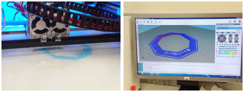
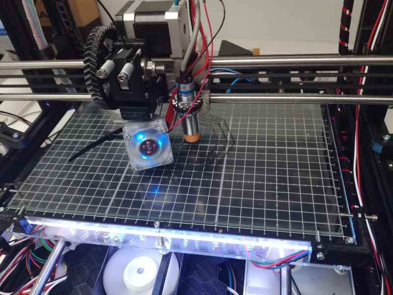
Printing in Leapfrog Creatr
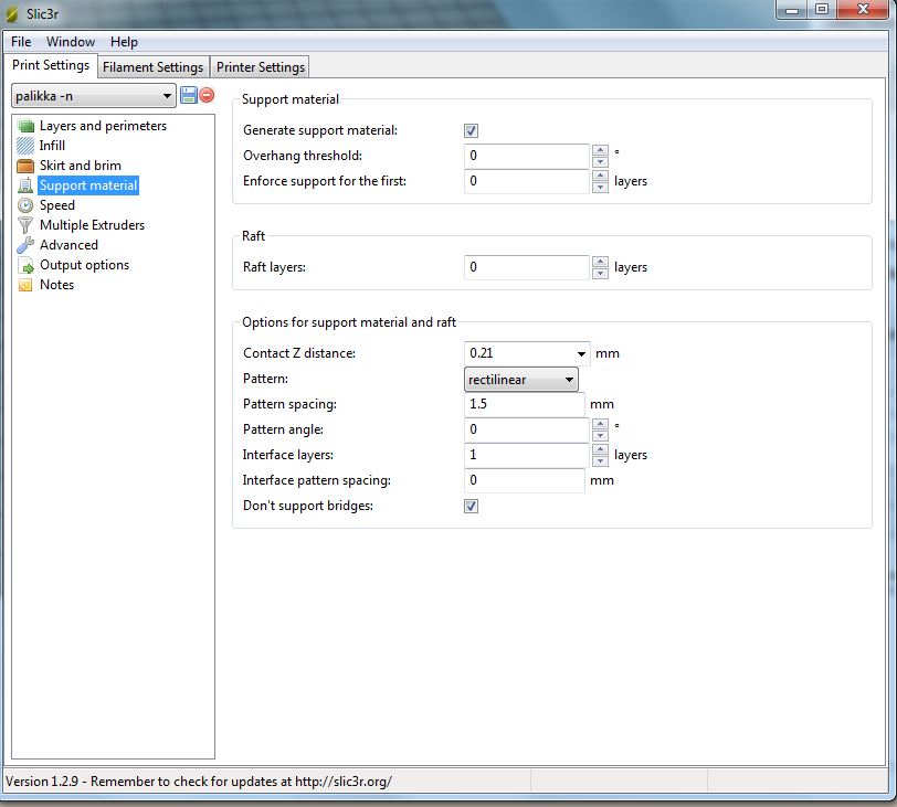
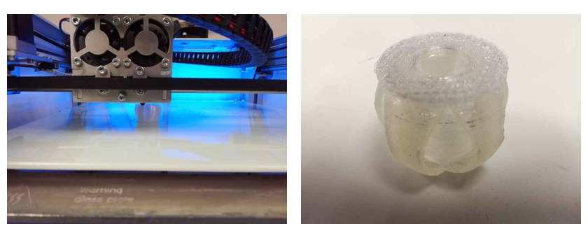
The process was more or less similar as the previous one. However, in this case I utilized Repetier software for printing. I utilized Slic3r to slice the stl file. In this case the printing was a little more challenging, so I decided to place the piece on its bigger circle. The inner ball stands a little bit out. Hence, I needed support material for the outer sphere (Figure 34) It turned out to be a successful decision.
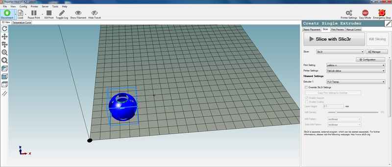
I utilized almost default settings.
It took around 40 minutes to have the piece ready. See in Figure 36 (right) how it looked like after getting it from the printer.
And here are the results:
Design rules of our printer
This week's group project consisted on checking the desing rules of our printer. I did the group work with Natalia Shevchuk, Jari Pakarinen and Mikko Toivonen
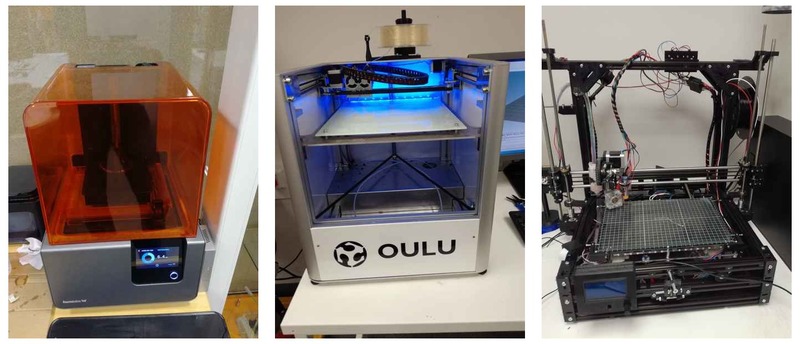
We have four printers in our Fab Lab:
- Leapfrog Convertr
- FormLabs Form2 2
- Stratasys Fortus 380mc (Not working at the moment)
- One self-made 3D printer by Mikko (he likes to call it Chrysion).
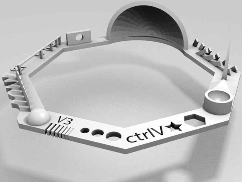
We decided to compare them taking an already existing existing test for printers we found in Thingiverse. This test measures the following dimensions:
- Nut, Size M4 Nut should fit perfectly
- Wave, rounded print
- Star, Sharp Edges
- Name, Complex Shapes
- Holes, Size 3, 4, 5 mm
- minimal Distance: 0.1, 0.2, 0.3, 0.4, 0.5, 0.6, 0.7 mm
- Z height: 0.1, 0.2, 0.3, 0.4, 0.5, 0.6, 0.7, 0.8, 0.9, 1.0, 1.1 mm
- Wall Thickness: 0.1, 0.2, 0.3, 0.4, 0.5, 0.6, 0.7 mm
- Bridge Print: 2, 4, 8, 16 mm
- Sphere, Rounded Print 4.8mm height
- Sphere Mix, 7 mm height
- Pyramide, 7 mm height
- Overhang: 25, 30, 35, 40, 45, 50, 55, 60, 65, 70°
- Warp, does it bend?
- 3D Print Font, optimized for 3D printing
- Surface, Flatness
- Size, 100 x 100mm x 23.83 (10mm width)
- Spike, minimum Layer Time, 21 mm height from Bottom (include Baseplate)
- Hole in Wall, 4 mm diameter, check for proper print
- Raft Test, raft should be just under the model
- Retract Travel, check retract settings for longer travel
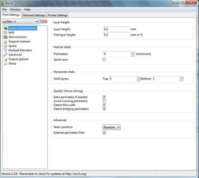
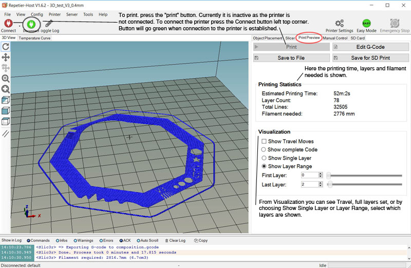
We used Repetier software to slice the model, set up the printer settings and send the model to print both for Leapfrog and Mikko's printer. Next I show a picture with the main settings we set up for the printer. The model took around 1 hour to print in both Mikko's and Leaprfrog printer.
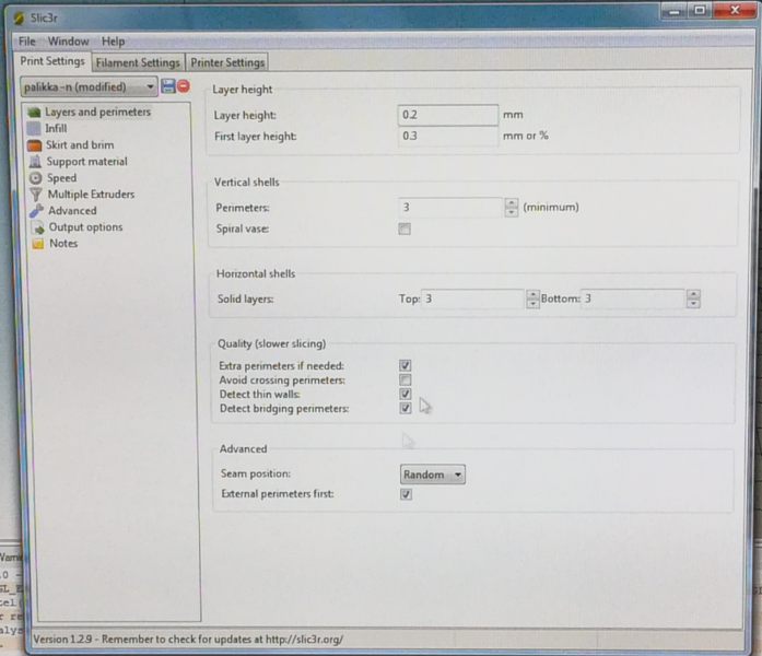
Jari wrote an excellent tutorial with the different settings of Repetier software:


For the FormLabs Form 2 we utilized Preform software, a proprietary software from FormLabs. The UI was quite simple. We utilized default settings and a resolution of 0.05 mm. Although, you could modify the points where the print place the supports, we utilized the default ones. Again Jari made an excellent work documenting the UI so I will copy here his screen shots.
A few things that grab my attention from this printer were: (1)the model was printer upside down, hence it is very important that the support material is located in the right position; (2) after the model is printer, you must submerge it in isopropanol during aprox. 20 minutes (in our case we had to buckets in which the model stayed 10 min each); (3) although the support is easy removed with a plier, sometimes, the support material is in inner parts of the object, difficult to access, hence it is really important to think carefully where to place the support material; (4) the resolution of this printer was amazing.
The results after printing the three models are shown in Figure 45.
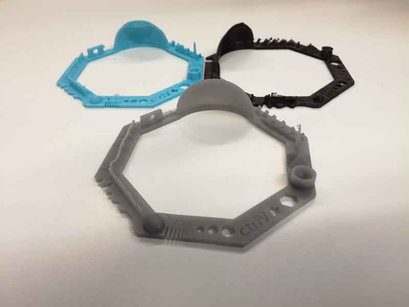
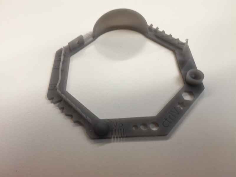
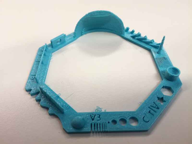
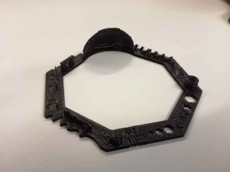
In her weekly summary, Natalia has shown in a table how different machines pass the different tests. I will make here a short summary of my own observations: (1)The quality of Form2 printer is much superior than the other 2. It passed all the tests except the minimal distance (the wall located at 0.1mm was not printed) and the Z-height (the step at 0.1mm was printed was had to be cut in order to extract the support material. Even the spike were printed correctly. In the bridges some of the material was very thin; (2)The Creatr behave quite nicely although it had multiple imperfections. The text were legible, however, it did not manage that good with the wall thickness since it could not print the 0.1mm wall. The bridge had better quality than the Form2. In addition it manage to print all angles except the 70 (it printed it but left material as a support). The spike was not sharp at all;(3)Mikko's printer got the lower quality (still work in progress). However, it managed to pass majority of the tests; (4)None of the printer printed the exact size of the shape. There was an error of +- 0.5 mm in the external size of the figure in all the printers. I guess changing some of the settings we could tune better the results.
Resources utilized
- Sense 3D scanner (3D systems): scanning small and big objects
- Sense 3D software (3D systems): acquiring data and creating 3D model
- Nikon D80: taking pictures of an object
- Autodesk Remake: creating a 3D model out of pictures
- Repetier software: to slice 3D models and send them to print
- SolidWorks: to generate the 3D models
- LeapFrog Leapfrog Creatr, FormLabs Form 2 and Mikko's 3D printers
Reflection
Summary
During this week I did my first 3D scanning ever. Furthermore, it is the first time I 3D print an object with almost fully understand of the different settings (thanks to Mikko's explanations). It has been also the first time that I have been using the Form2 printer (stereolithography). I realized the importance of knowing correctly the limitations of each printer and of understand the settings in order to produce a high quality 3D model. I have also realized through the tests that 3D printers still need a lot of improvements. The output quality of the different models is not yet as perfect as many manufacturers assure.
Main difficulties
I think the main difficulties from the scanning part is setup correctly the environment. I had to repeat multiple times the two scannings I did in order to get successful results. With respect to the 3D printer, there were many different concepts to learn in the printer settings. A correct configuration is crucial to have a successful printing
Main learnings
In photomgrametry we need to consider following aspects: lighting, the sharpness of the pictures and the background. It is better to use some markers to help the software. Sense 3D (using laser in a similar way as kinect) supports better modifications in the lighting and picture background. Photogrametry using external software such as Autodesk Maker takes quite a lot of time. In my case, processing 50 pictures took around 2 hours in Autodesk servers.
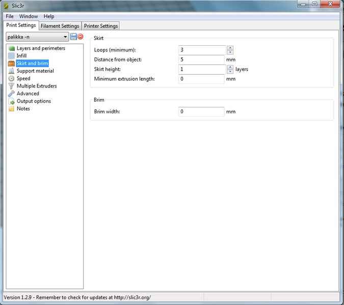
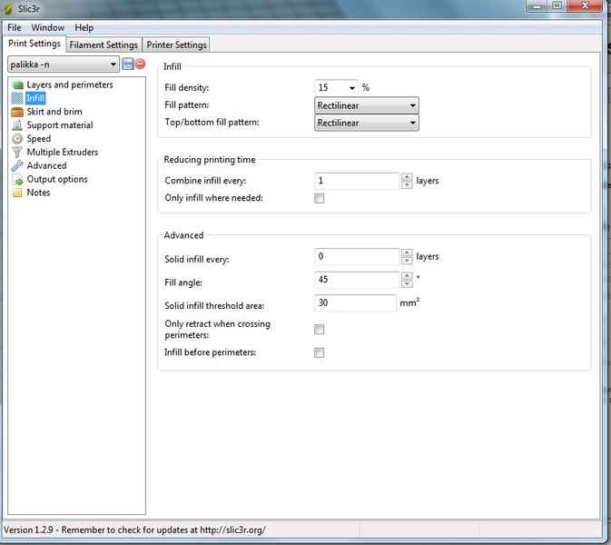
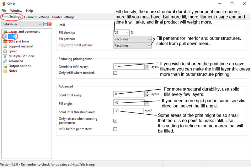
I finally learn different settings for the Leapfrog printer: For instance, I learnt why the skirt and brim are useful, when to utilize more or less infill and which is the best configuration for the vertical and horizontal walls. In addition I learnt how to use Form2 printer.
After Neil's review I learnt that would have been easier to use some kind of visual clues when using photography based scanning. This would facilitate the algorithms to locate the objects. For instance, using a symettric pattern of simple geometric figures such as circles or squares.
Models files
- 3D scanned .stl models of the mouse and the radio
- The Solid works model files for the inner ball, outer ball, and the whole assembly. I include also the stl file