
Week 14. Composites.
During this week I frabicate a frisbee using composites
Tasks
- Read the material safety data sheet (MSDS) and technical data sheet (TDS) for the resins that you're using
- Design and fabricate a 3D mold (~ft2)
- produce a fiber composite part in it
Process explanation
Setup and coupons
Mold design
For this week I wanted to design a Frisbee. Initially I planned that it has the official measures and shape for Ultimate Frisbee tournament, but after a while working with the design I realized that some of the shapes were really hard to get, so I got certainly design freedom. For this design I used Fusion 360.
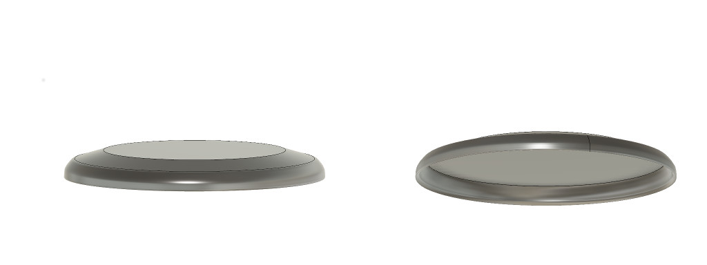
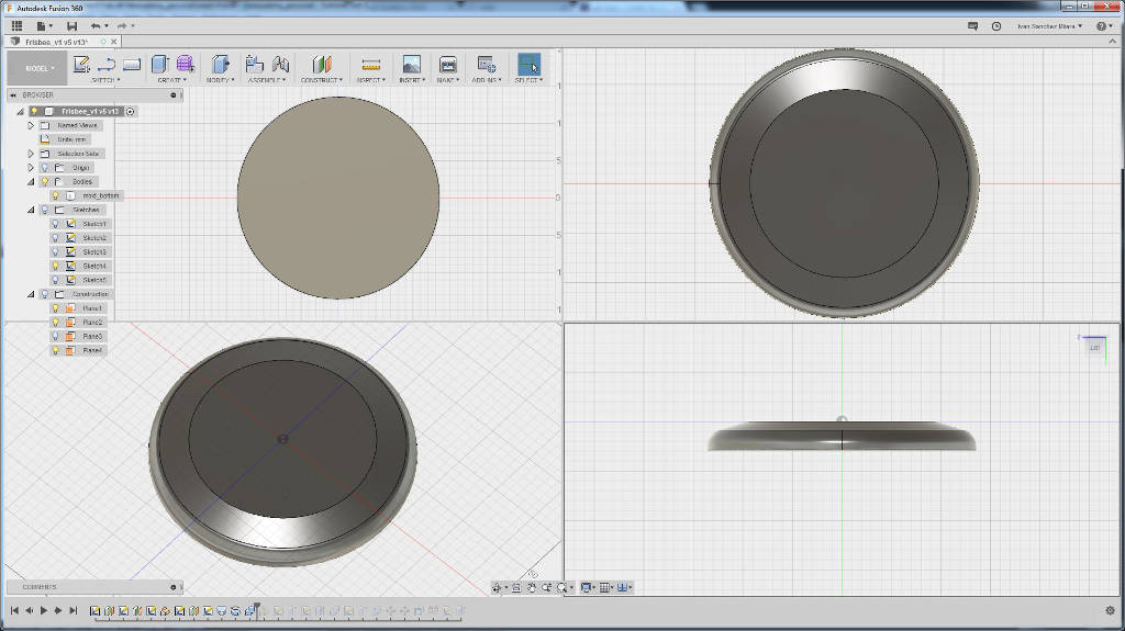
Initially, I designed the frisbee itself so I could use it later to create the mold. Figure 1 shows the initial design of the frisbee.
To achieve this model I followed the next steps:
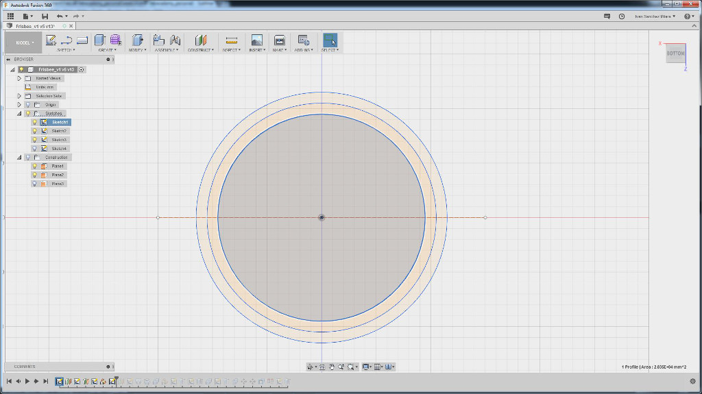
- First I created the upper form. Using the Construct > Offset plane I drew three parallel planes parallel to the XZ plane and separated 1.5 cm among them (Figure 2)
- I draw 3 different concentric circles, one in each one of the previous planes. The size were 19, 21, and 23 cm.
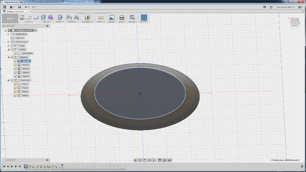
- Then I utilized the Create > Loft tool to give the top shape of the frisbee.
- Next step was to model the bottom part of the frisbee. To that end I create a profile with a round shape at the end using splines and revolve it using the Create > Revolve tool. This is the frisbee model I used for to create the mold. To create the model shown in Figure 1, I utilized a slightly different revolving profile (Figure 6).
- After that I used the Modify > Combine tool to create the frisbee model.


Once I had the frisbee model I had to create the mold. In the begining I thought to create just one side mold, but Antti suggested to use two side molds due to the shape being very rounded. He commented that sometimes the vacuum bags are not the best in this type of situation. Hence, I opted for the two sided mold.
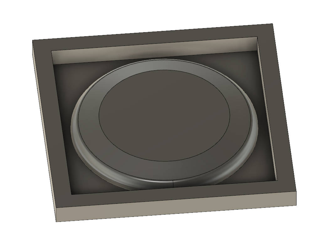
To build the mold I created a container box to attach the Frisbee from Figure 7 (bottom part of the mold). I created first a cuboid extruding one rectangle. After that, I created a smaller rectangle which defined the box wall. The profile is extruded cutting the previous cuboid. Finally, using the Modify > Combine > Join I attached the frisbee model to the box, creating the bottom of the mold. (Figure 8)
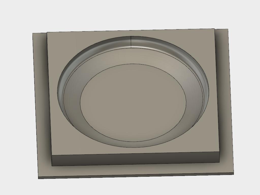
After that, I created a similar box for the top part of the mold. I used the same size as the previous one. When I extruded, I utilized a little bit different settings. I extruded using an offset of 6mm (to serve as a top lid), and I extruded till the bottom part of the mold. I chose Generate a new object instead of utilizing any boolean operation

A better view of the top mold is shown in Figure 10.
Next, I position in such a way that both molds can be machining at the same time. After rotating the top mold 180 degrees and translate it (Move tool) to an adequate position, we got the two parts of the molds as shown in Figure 11. I used the Modify > Align tool, so the top part of both molds are located at the same height.
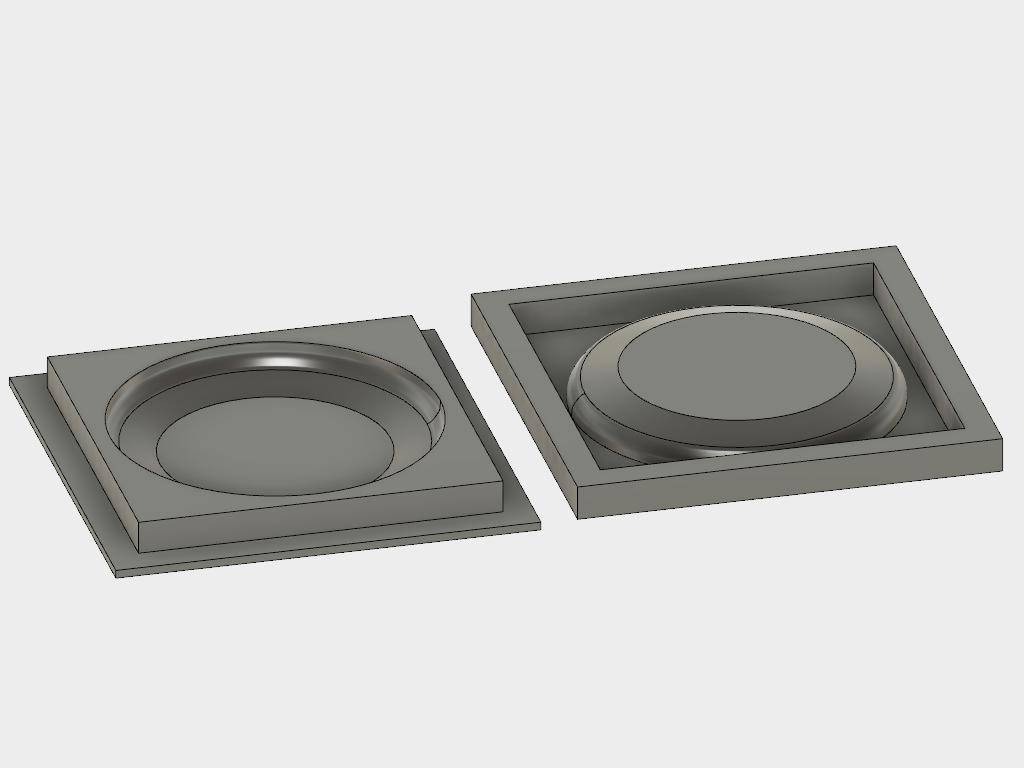
I need to leave some space between one mold and another to insert the composite. I used also the Offset face by means of the Modify > Pull tool, to increase in 1 cm the height of the top mold lid. In that way, I leave some space to add the composite in the mold.
Mold machining
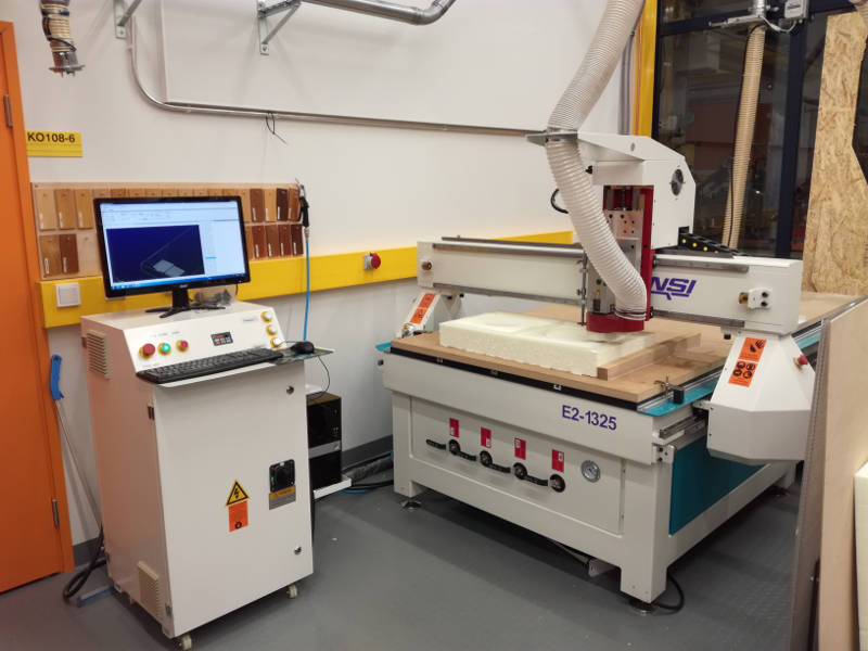
Next is time for generating the toolpath and machining the mold. I utilized also Fusion 360 CAM Workbench to generate the toolpath. As in Week 7 I utilized a CNC router RENSIN E2-1325 with Vacuum table. I utilized a ball end milling bit of 6mm of diamater with a flute length of 20mm. I utilized 10 cm depth foam to create the molds.
For creating the toolpath, I followed the next steps
- Change to Fusion's CAM workbench and created a New setup.
- Next step is defining the work origin and the stock characteristics (Figure 13).
- My models have the axis changed. Z axis should be the vertical axis. So I had to modify the axis direction in the Setup tab. I chose to select the z and x axis directions. I set the origin of coordinates in the top-left corner of the bottom mold.
- I did not defined the dimensions of the stock. Instead, I utilized the Relative size box from the Stock tab. This option generates a stock big enough to host the objects to be machined.
- I created my own tool, since not of the available ones fit the one I was using for this work. From Manage > Tool library I copied an existing 6mm diameter ball ended milling bit and changed some of the properties. For instance I set the Shaft diameter to 6 mm, the flute and shoulder length to 20 mm, the body length to 40 mm and the overall lenght to 63 mm (the real dimension of the bit). All the changes are shown in Figure 14. After changes were correct I pressed OK button.
- I planned three different operations: roughing, finalizing and define contours. With the first one I define the main shape of the mold but without details and removing the majority of the material. The finalizing operation create the details and remove marks from the milling bit, and the countours operation is used to cut the molds.
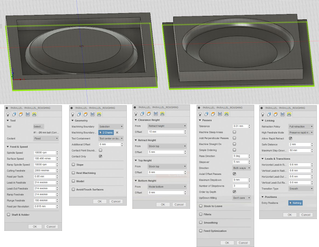
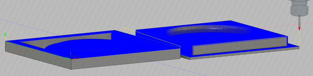
- For the roughing operations I chose a parallel strategy. Settings are shown in Figure 15. I utilized a Spindle speed of 10000 rpm, a cutting feedrate of 2000 mm/min and a plunge feedrate of 150 mm/min. Feed per revolution was 0.015mm and Feed per Tooth 0.05mm. The the stepover is 5mm, and the Axial Offsets Passes is activated.. I utilized the bottom surface of the two molds as machinining boundaries. Key parameters in the Passes tab are:stepover (5mm), that is, how close the paralell tracks are milled and the maximum step down (9mm because the flute length is aprox 10 mm) and the Number of step downs (3), which defines how deep goes each path. The path is shown in Figure 16. The estimated time was 2 hours.
- For the finishing operation I chose a similar set up. But in this case the Stepover was 1mm while I removed the option for Axial Offsets Pasess. Hence, there was just one pass. The estimated time was 2:27 min. Settings are shown in Figure 17.1 feed rates and speeds are indicated in the captions.
- Finally, I defined the bottom plane of both objects as 2D contours to be cut using the 2D > 2D contour strategy. Settings are shown in Figure 18 feed rates and speeds are indicated in the captions. The toolpath is shown in Figure 19. The main changes I did were in the Passes tab in which I activated the multiple depths (9mm each). The estimated time was a little bit less than 9 minutes.
- The last operation after creating the toolpath is to simulate it (using the Actions > Simulate tool). I checked all the paths and I noticed that there were multiple collisions (see Figure 20). Majority of them, specially in the finishing part was due to shaft collision. It is either cause because a bad definition of the tool, or because the application does not recognize that I have run a roughing step previously and hence removed a big amount of material. Hence, it thinks the shaft will hit the stock. I decided to continue, in spite of the collisions detected.
- The last step is generating the machine code for the CNC router. I utilized the Actions > Post-process tool to that end. As explained in Week 7, our Fab Lab has defined its own Post Process interpreter to transform Fusion output G code into the dialect our CNC router understand. The name of the file was added in the Post-configuration field shown in Figure 21. After pressing the Post button, Fusion generated the adequate G-Code for my process and my CNC router.


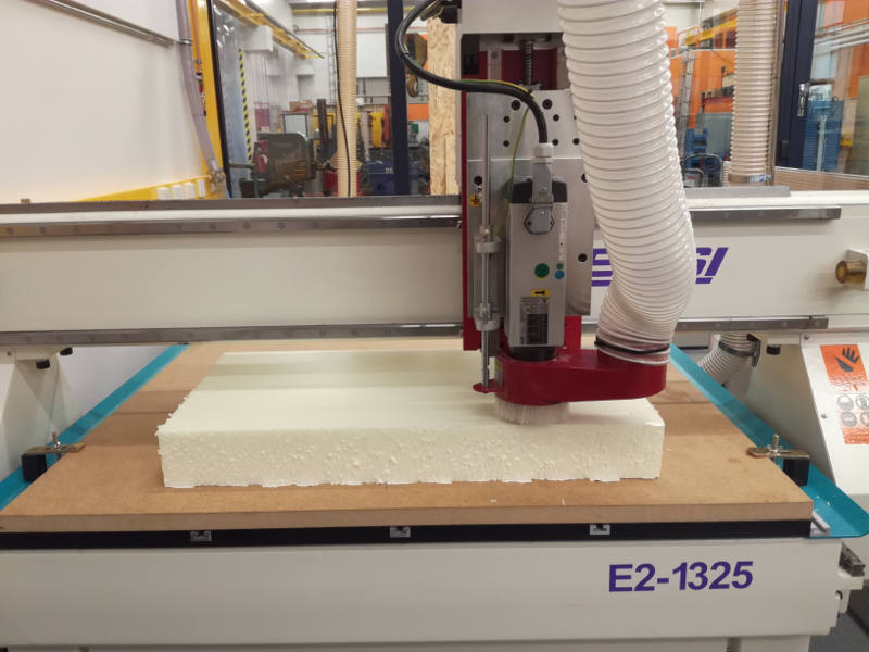
Finally, it is time for machining. I utilized a CNC router RENSIN E2-1325 with Vacuum table, although we did not utilized the Vacuum. The sacrificial layer was a 5cm stock of MDF, fixed to the router surface through some fixtures. I fixed the foam's 10cm stock to the sacrifical layer using two side tapes (Figure 22)

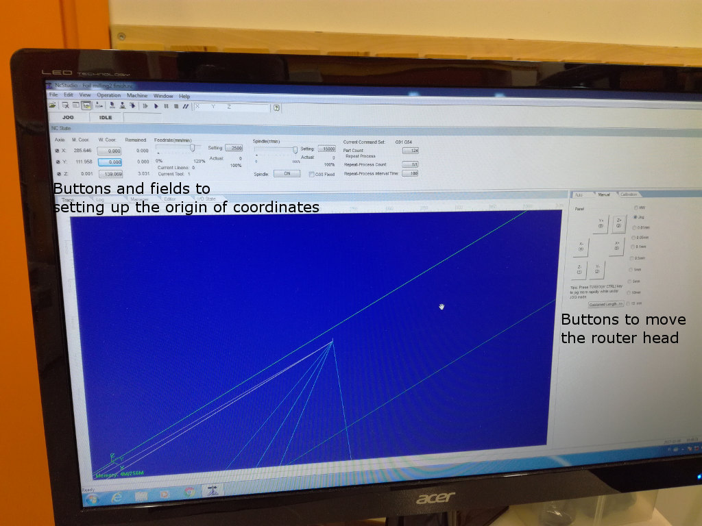
Then I had to define which is going to be my origin of coordinates. When using CAM Fusion's workbench I defined that my origin in the stock would be at the bottom-left corner of the top stock's surface. Hence, I need to define that position in the machine. I utilized the CNC's UI to set up the origin of coordinates (Figure 23). Just by moving the head of the router with the UI buttons I placed the milling bit in my desired origin. After that I pressed, the W/coord button for X and Y axes. I did not place the origin exactly at the border of the stock, since I did not defined any offset in my CAM's design. Hence, I should leave some space in the borders.
To define the Z origin I tried first the machine calibration (as in week 7). However, it did not work due to the height of the stock. When the machine tries to go up after setting the limit, it launched a "warning" telling that the upper vertical limit of the machine was reached. Hence, I had to use the same calibration as with axes X and Y
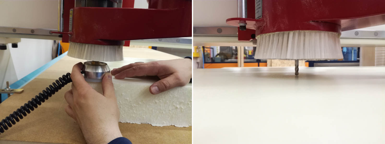
After checking again that the stock was correctly fixed to the sacrificial layer just pressed the Start button from the UI.
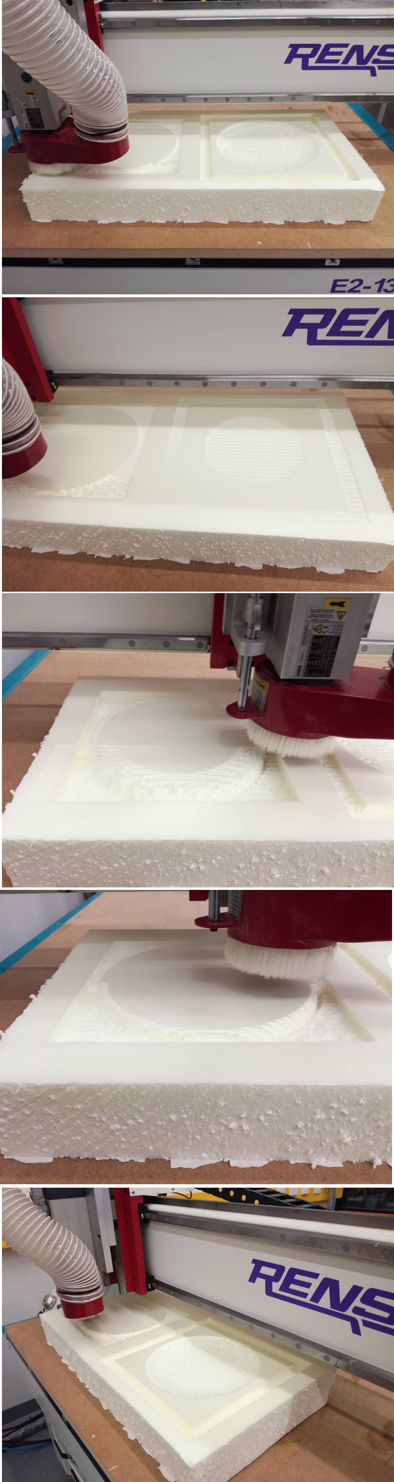
At some point I noticed that the left side corner was losing grip with the sacrificial layer, and leaning up therefore. Jani, my supervisor, suggested to try to put a piece of wood with two sided tape at the bottom (so it sticks to the sacrificial layer) and at the left (so it sticks to the stock). In that way, we try that to fix again the stock to the surface using the piece of wood as a tool. Of course, we had to pause the machine for that purpose. This worked for a while but after a few minutes, the stock started to lean up again. The fact that the stock was not fixed correctly, had later consequences when we cut the mold.

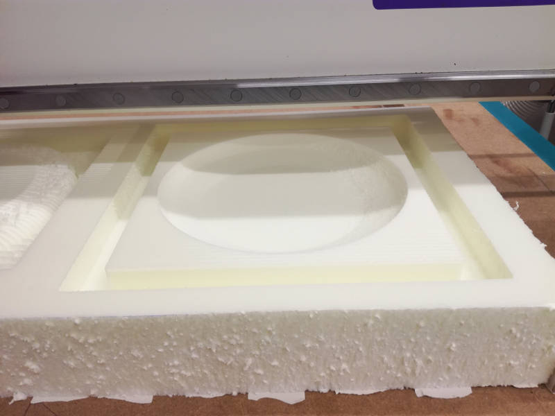
The finishing processes went on, and finally I got the mold ready (Figure 29)
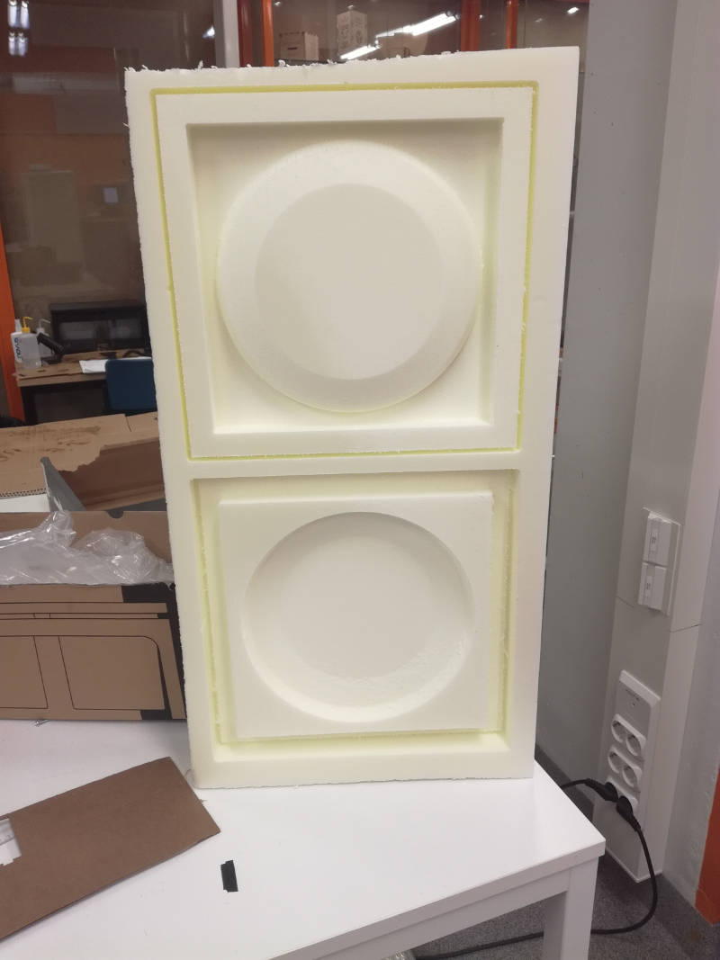
Since it was two sided mold, I had to cut the two pieces using the saw since the router did not have appropiate milling bit to cut 10cm stock. The top and bottom part of the mold are shown in Figure 31. For the parts that did not fit in the electrical saw I used the manual saw.

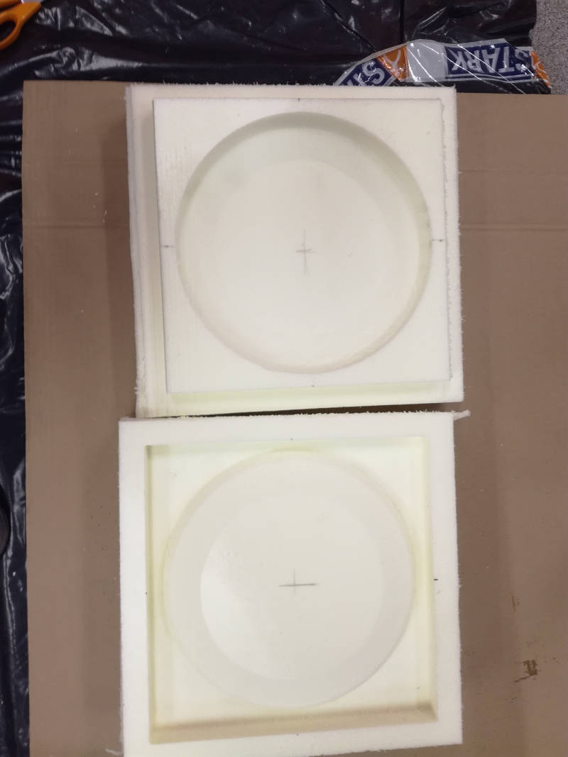
The molds did not fit perfectly, actually I had to apply a lot of force to make them fit, so I had to sand the walls of the molds removing around 1mm per wall. This happened in spite of the fact I left an offset of 0.5 mm between the upper and bottom part of the mold. The problem might be caused for two reasons: either the resolution of the machine is less than 0.5mm or because the stock was not correct fixed to the sacrifical layer and slightly moved up and down.

Finally, when the molds were ready I started to create the composite.
Creating the composite

Understanding the MSDS and the TDS
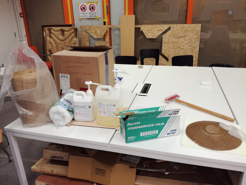
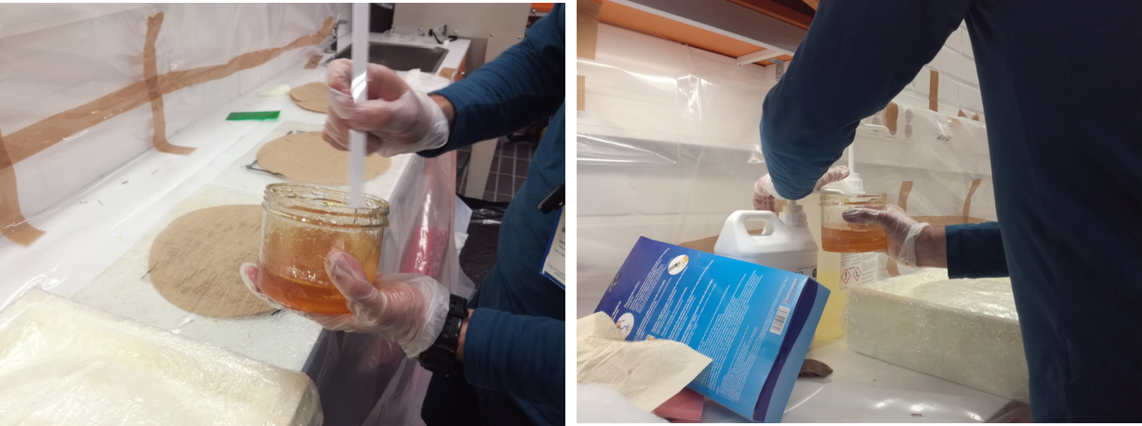
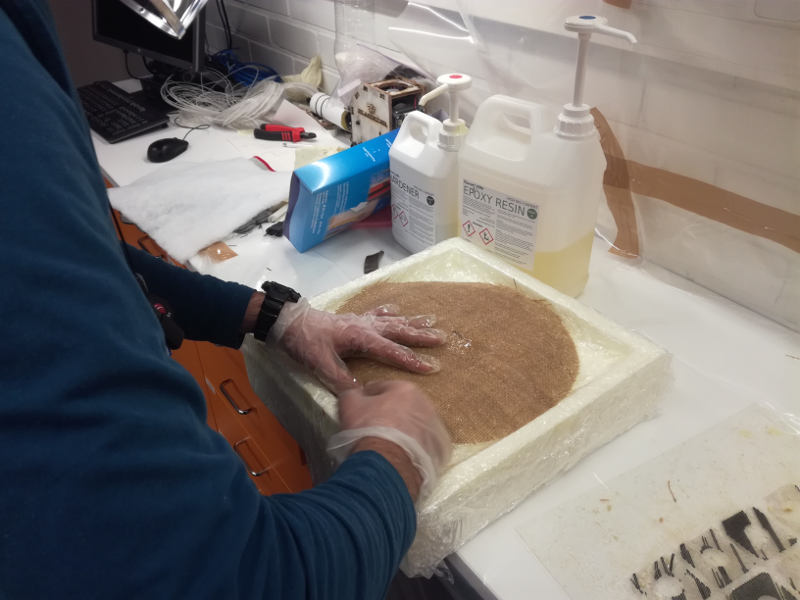
For the composite we used Burlap Fabric and Super Sap One as a resin. The Super Sap One needs to different components: the resin itself and the hardener. The Material Safety Data Sheet (MSDS) of the resin can be found from here while the Material Safety Data Sheet (MSDS) of the Hardener can be found here. From the MSDS, it is clear that I should use gloves and protective mask for the face in order to manipulate the both the Epoxy and the harderner. In addition I should use some kind of protection for my clothes. If they get some epoxy / harderner, I should throw them away. In addition, if any of both products get in contact with my skin, I should inmediatly wash the area with abundant soap and water. It is important to have adequate ventilation.
The Technical Data Sheet reveals that the mix ratio in volume is 2:1. Fortunately, the container have a dispenser, so I do not need to worry about taking separate measurements. Pot life (that is, the time in which the mixture can be applied) is just of 18 min , so I should hurry up when applying the resin to the fabric. In addition the cure time is of 7 weeks, so it won't be totally cure till next week.
Fabricating the composite
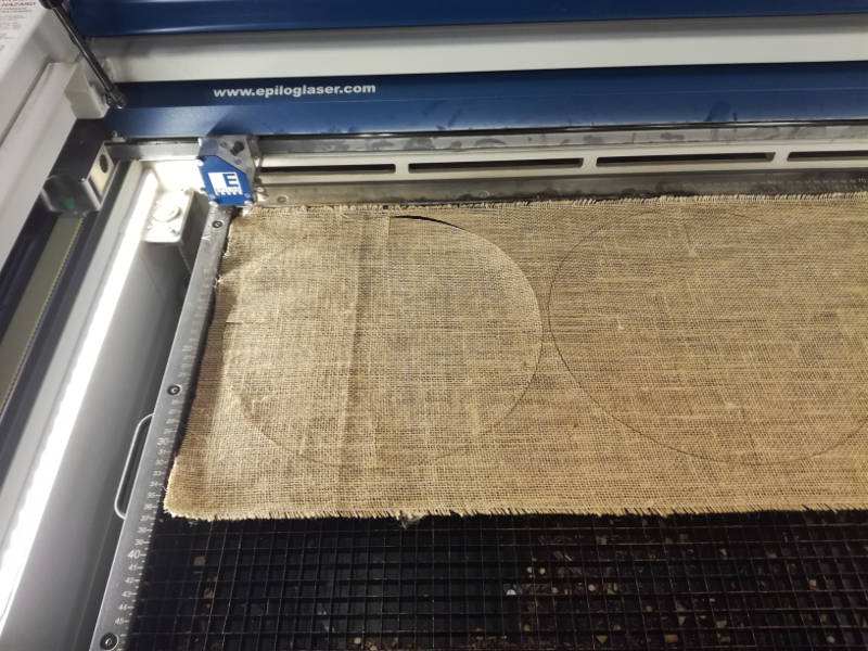
First thing was figure out the correct surface and shape I had to use for the fabric. I decided to draw by hand the size after putting it on the mold. Once I knew the correct size of the circle (15 cm of radius), I draw it with Inkscape and cut it with the laser cutter. Note that I did 4 darts for the fabric. I used a test piece of fabric to find the right settings of for the laser cutter that turned out to be 50% - 50% - 50%
The process to create the composite was as follows:
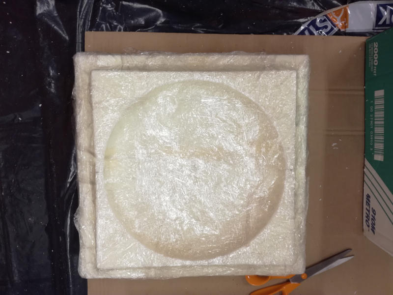
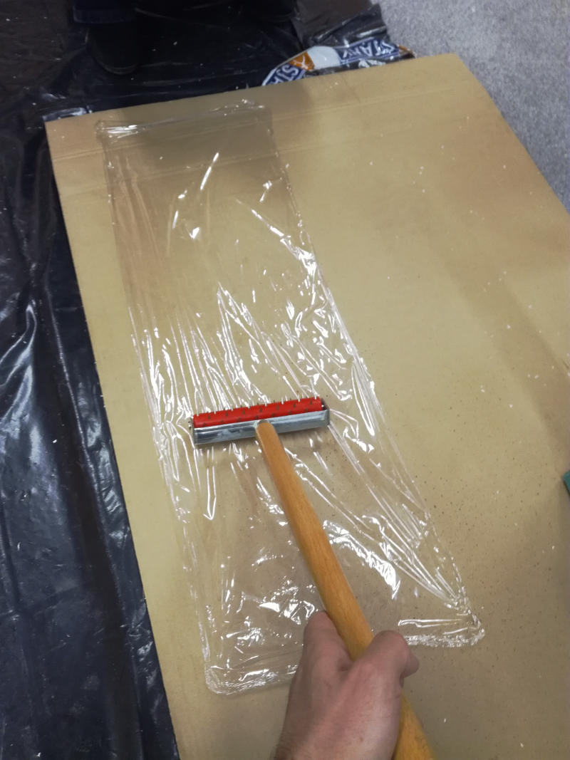
- Wrap the molds with two layers of transparent film. This was not an easy task due to the depth of the mold. It was difficult that the film stays on the mold surface.
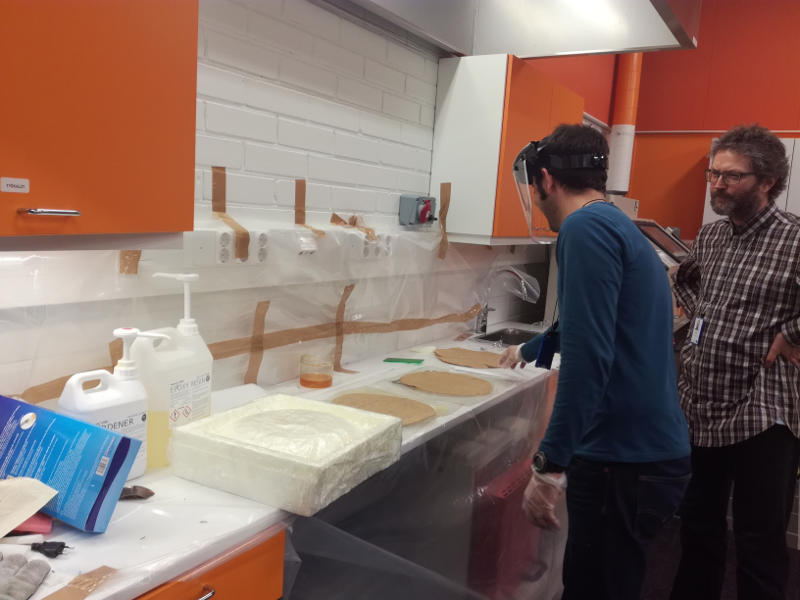
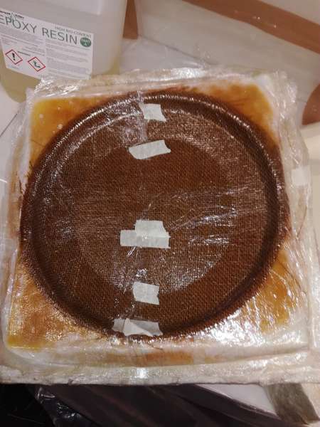
- Mix the epoxy resine and the hardener in the correct proportions (we used SUPER SAP ONE). The applicator was really helpful for that.
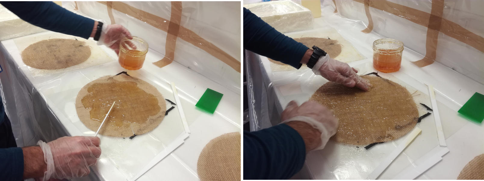
- Spread the mix on the fabrics. First using a stick. After that, I used the hands (wearing gloves, of course) to spread the mix more evenly. I removed the excess of liquid with the stick.
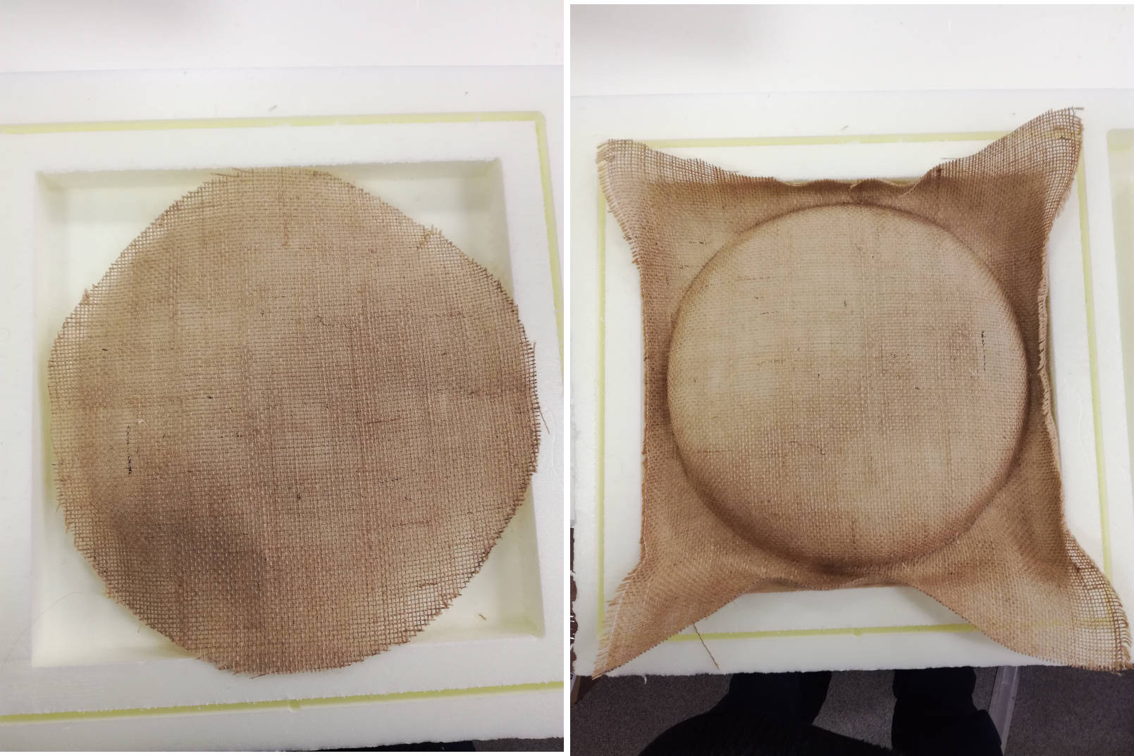
- Place the fabric on the mold. Give adequate shape to the darts. I tried to push the fabric as much as possible to the bottom. In total I add 3 layers of fabric. Let's hope that this is enough.
- Put a layer of transparent film in which I have done previously some holes
- Put a layer of polyester on top of the film
- Put a new layer of transparent film on top of the poliester. Put the upper part of the mold and cover again with a new layer of transparent film.
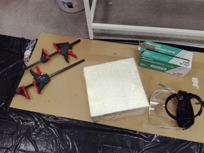
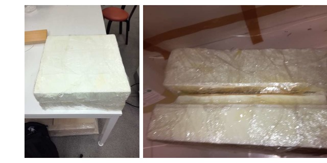
- Now, we need to compress the mold putting some weight.
- Close the mold and fix it using clamps and some extra weight to get the necessary compaction


After waiting four 24 hours (although the curation time was just 4 hours) it was time for unmolding
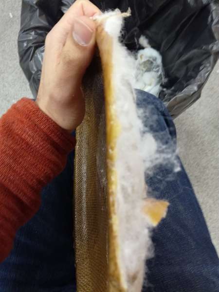
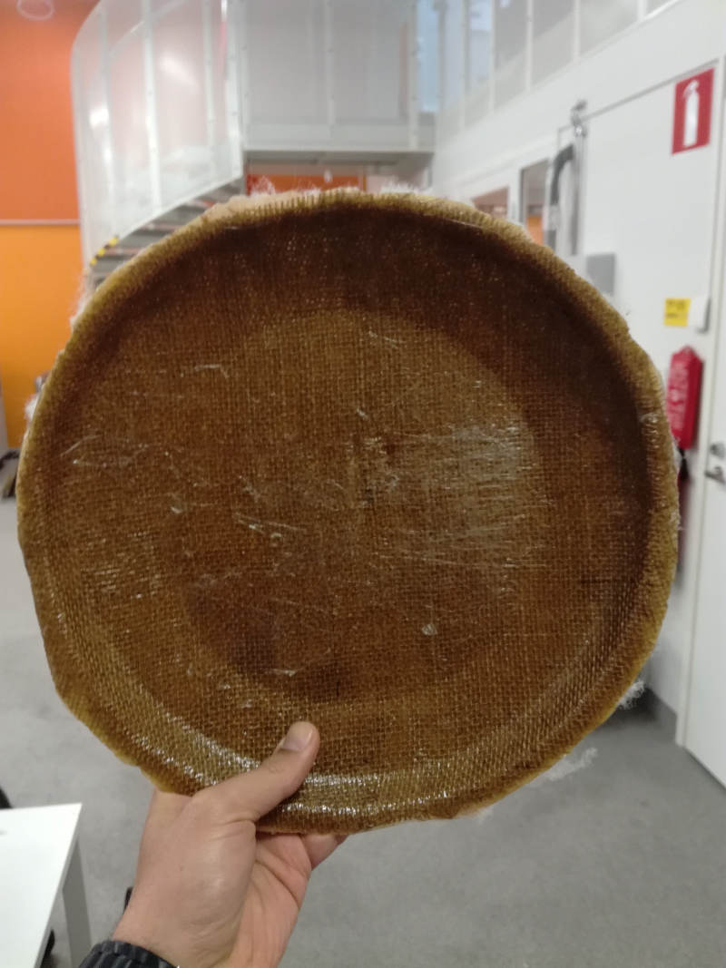
The composite looked good. It was strong, not very flexible and it produced the characteristic sound when hitted. It got adequate shape, and the bottom part looked really good.
However, it looked like I put too much resin in the fabric, since the resin soaked trhough the transparent film with holes and the poliester. It adhered to the poliester, making really hard to remove the poliester from the fabric.
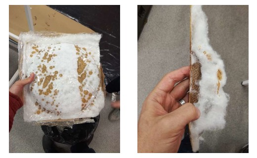
I will check how can I solve this problem. I guess the only option is sanding the material.
Resources utilized
- Fusion 360 for designing the molds
- RENSIN E2-1325 with Vacuum table to do the molds
- Foam to create the molds
- Burlap fabric
- Super SAP one Epoxy resin and hardener. The corresponding data sheets are found here for the Epoxy and here for the hardener
- Transparent film
- Polyester
- Clamps for compaction
Reflection
Summary
My goal was to build a light frisbee out of composite. During this week I designed and machined a 3D mold and made a composite for fabric and epoxy resin and hardener. I use clamping for compaction.
Main learnings
This week I learnt how to create a 3D mold for machining using different Fusion 360's CAM strategies. I also learnt the process of creating simple composites out of fabric and epoxy resin. I learnt how to read the Epoxy Safety Sheet. I also learnt how important is to have some offset in both parts of the mold so they fit correctly.
Main difficulties
Not big difficulties during this week. The biggest mess has been having to sand the walls of the mold so they fit correctly together. In addition, it seems I added too much resine to the fabric. Hence, it went out from the breather and got glued to the polyester. I could not remove it from there. Only solution was sanding the whole frisbee.