2017
Iván Sánchez Milara

©2017 Iván Sánchez Milara | Template by Bootstrapious

This work is licensed under a Creative Commons Attribution-NonCommercial-ShareAlike 4.0 International License.
Final project. Modular multimeter
Project proposal modular multimeter
Problem description
From previous discussion from our Fab Lab director, I learnt that there is a need to be able to build your own multimeters and other measurement equipment at Fab Lab. There are some Fab Labs in which access to the most basic equipment is very challenging / expensive. In addition, one of Fab Lab goals is to build the necessary machines that are needed in the Fab Lab itself, using exisiting tools.
In addition, my research topics is related to how technology in general and digital fabrication in particular can be used for education (both K12 and university education). Building different measurement equipment by yourself (with the help of adequate tutorials) can help to understand concepts in the field of mathematics, physics, electronics and programming. However, teaching material should have appropiate scaffolding allowing learners to acquire knowledge in a structure way. However, building a whole measurement equipment by oneself would require a significant amount of time, knowledge and effort. However, building just a module for a particular equipment would be more feasible in order to incorporate this activity as part of the teachers toolset.
Based on the two previous points, I decided to design and fabricate a modular Fab-multimeter for my final project, that can be easily replicate in any Fab Lab around the world.
Initial project proposal
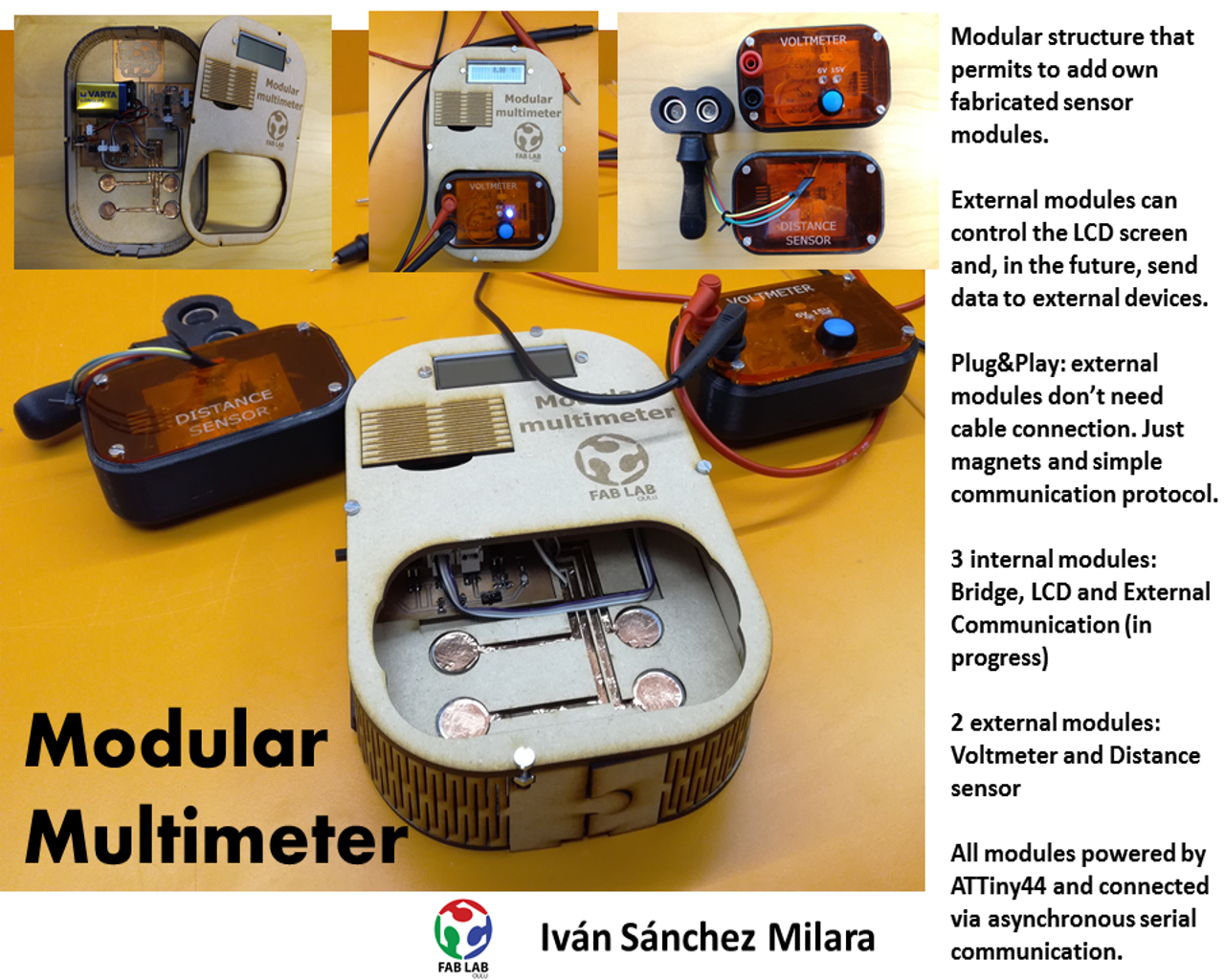
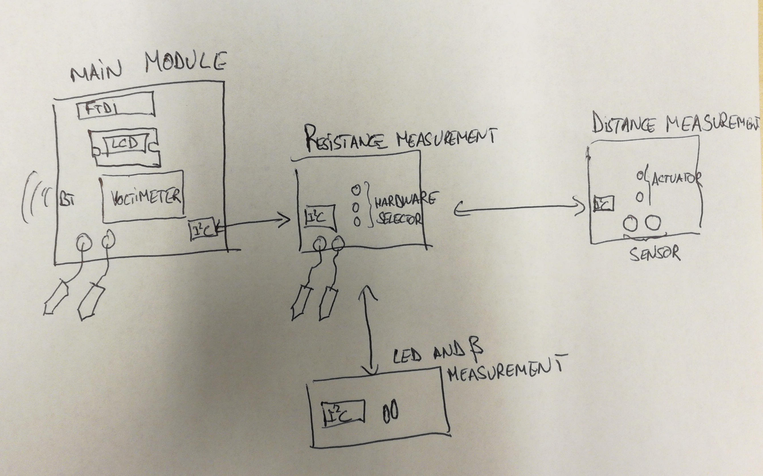
The idea is build a multimeter with very basic functionality, but with a modular architecture that enables adding extra functionality as independent hardware-software modules. Modules can be physically attached or removed from the multimeter.
The main module consists on LCD screen and an asynchronous serial port to communicate with a PC (FTDI - USB interface). In addition, if I have enough time, it will have a bluetooth module that permits sending read data to an external device (e.g. a mobile phone) to be further processed there. The main module contains a I2C interface and permits to connect other modules to it, enabling the use of LCD and communications capabilites of the main module to other modules. This module, is powered with 5V.
I am planning to implement a set of external modules that can be connected to the multimeter: voltmeter, conductance detector, resistance measurement, and LED voltage measure and distance measurement will be other modules that I am planning to implement.
Concrete details
What will it do?
I am building a modular Fab-multimeter. It is basically a measurement device that presents data on a LCD screen and can send it to an external computer. Different measurements modules can be attached to the device, and connected to the main module via I2C network protocol. Those devices will be able to utilize the LCD and send data through the serial port. Different modules should be easily attached and deattached from the device. I am planing to build a voltmeter, a resistence measurement and a distance measurement module for the final project.
Who's done what beforehand?
I have found one commercial DIY multimeter kit from Sparkfun. It is based on the ATMega28 microcontroller. I also found one tutorial in instructables explaining how to build a multimeter's arduino shield. In previuos years one Fab Academy student have built a simple oscilloscope. In Fab 12 was built also a nice looking oscilloscope with its own LCD screen.
I am planning to have a similar module for the LCD as the one I have used during the Output devices and Networking assignments. I also built a measurement module similar to the one I built for Input devices. The rest of the modules and the multimeter case is under construction.
What materials and components will be required? Where will they come from?
I will use materials available in the Fab inventory.All the modules will use ATTiny 44a as its microcontroller. I will use standard electronic components available in the Fab Lab. The external case and the small cases encapsulating each module will be built out of acrylic and MDF. I will use also some vynyl to create a simple UI for the board.
How much will it cost?
The components of each board will cost in average 4.5 dollars, so 4 boards will cost around 18 dollars. In addition, we need to include the costs of the FR4 to build the boards, the MDF and acrylic for the case. Based on the previous calculations I estimate that the whole system (including the external modules) would cost around 22 - 30 dollars.
What parts and systems will be made?
All modules will be connected through I2C protocol. I will fabricate the following modules:
- LCD screen module: To visualize measured data from other module
- Voltmeter (main module): To measure voltage (till 20V). I am planning that this module has also access to a computer utilizing FTDI serial-usb adapter.
- Resistance module: To measure circuit resistance and continuity
- Distance measurement module: To measure distance.
- External connection module: to connect to external devices
- Main module: it is just bridge that connects the different modules and power them. It perform basically the data and power distribution.
Except the internal modules (main module, communication module and LCD screen module) all the other modules can be added / removed from the case easily (plug&play). If I have time, I would like to implement a simple application in the computer to visualize the measured data.
What tasks need to be completed?
- Design and fabrication of the 6 modules.
- Testing 6 modules separated
- Testing whole system
- Design and fabrication of plug&play boxes for the external modules.
- Desing and fabrication of the external case.
- Design and fabrication of the stickers for the external case
- Implementation of simple application in the computer to visualize the data.
What questions need to be answered?
- What are the limit current/voltage I can use?
- What kind of electrical protection can I have for unproper use of the multimeter (e.g. too much voltage/current in the input)?
- What is the best way of measuring voltage? What is the best way of measuring resistance?
- What is the best way of implementing the interface between the main module and the rest of the modules using I2C protocol?
- What is the best way of building the case and the plug&play modules? How should I attach the PCBs to them?
What is the schedule?
I have two week's time to finish the work. The schedule would be as follows:
29th May - 31st May : Fabrication of the LCD and the distance measure module31st May - 4thJune : Fabrication and implementation of the voltmeter4th June - 10th June : Implementation of code and network protocol10th June - 12 th June : Testing the circuits13rd June - 14th June : Designing the cases15thJune - 19th June : Prototyping, fabricating the case and circuit integration20thJune - 21st June : Final testing. Finalizing the video and slides.
How will it be evaluated?
My project will succeed if:
- I have at least two working external modules
- The measures can be sent to the LCD screen. The LCD screen should be able to show mangnitude an unit
- Modules should be added and removed from the system. If possible the usage of connection cables should be avoided.
- The accuracy should be in the range of the tens of milivolts for the voltmeter, in the range of centimeters for the disance measurement and in the range of tens of ohms for the resistance measurements.
- Data should be visualized in the LCD screen in real time.
- As an addition, an external device should be able to receive the data sent by the sensor module.
What processes am I going to use?
- Electronics design and production
- Embedded programming (using C)
- Output devices: LCD screen and LEDs
- Input devices: Voltmeter, distance sensor and resistance sensor
- Network: Different modules connected via Asynchronous Serial Communication
- 2D design: Vynil cutter for decoration / building circuits with a copper film
- 2D design: Laser cutting External case. It should include living hinges.
- 3D design and printing: For the cases of the external modules.
Dissemination plan
I would like to exploit the educational perspective of the project both for adult hobbyists starting in the worl of electronics and children in comprehensive , upper secondary and vocational schools in order to promote STEM. The modular idea of the project permits to study different sensors: how they work (physics), how utilize the sensor to measure physical phenomena and how to built electronic boards that utilize those sensors (electronic and engineering).
The main idea to make business out of this product is to provide a basic kit containing the main measurement modules and then instructions on how to design fabricate and connect additional modules. Next I will develop the idea further:
- The main kit consist on the voltmeter, the LCD kit and the box. This kit can be acquired by a company (that I might create for that purpose). There are two versions of the kit: one wit the product assemble and other just with the components and mechanical pieces.
- In addition, I will use open hardware and software licenses and upload both hardware schematics and code, as well as some tutorials with instructions on how to build this product, in the product website. This will facilitate other Fab Labs can replicate the project
- Additional kits (e.g. distance sensor, resistance sensor, communication sensor) can be acquired also from the company (in both versions: assembled and dissassembled). In addition, I would follow the same politics of open hardware and software. This will help to create a strong community that will help to advertise the product and also contribute in its development. Tutorials will be provided.
- I will create a community portal where people can present their own designs and tutorials.
- The core of the business would be in the organization of workshops, courses and tutorials where the different kits are used to present basic concepts of electronics and physics. Different versions of course and workshops will be organized for different target groups. One of the main target groups would be teachers. In Finland, with the change of the National Core Curriculum for Education in which project work and STEM are emphasized, teachers are struggling to prepare new type of pedagogical activities with the kids.
Infrastucture
- A website will advertise the product and provide tutorials. In addition, the website will have a shop where customers could buy the kits
- An additional website will be create to build a community. This website will have forum and space for people to upload their own tutorials.
- Once I have a stable version of the project, I would create a Kickstarter campaign that would help to get initial funding, basically to manufacture the kits.
Revenue source
- Selling kits and components
- Organization of Workshops and tutorials. In Finland one of the main targets would be teachers.
Final analysis
Time management
Although I managed to finalize the project on time, and I basically meet the deadlines I fixed in the previous week I calculate wrong the times. I made a mistake while designing the external boxes (I did not take into consideration that the cable connectors occuppy certain additional space). Solving the issue took quite a lot of time and made almost a miracle that I deliver the project on time. I should have started the integration in the much early phase. I should build the electronics and the mechanics in parallel and not in serie.
Regarding the time management techniques, it was almost impossible in the last days to work only the hours I have programmed. Actually, I would say that I have double or even triple the hours that I have planned for the project. I should have taken more realistic schedule because I finally ended utilizing a demand time management instead of a supply time management as I should have done. I managed to utilize the supply time management in the beginning of the project, though.
What tasks have been completed, and what tasks remain?
I have implemented two internal modules (main module and LCD module) as well as two external modules (voltmeter and distance measurement module). The voltmeter accuracy is in the range of tens of mV. The communication module has been designed and fabricated but the components has not been soldered yet. The resistance measurement module has not been started. All modules were tested separately and they are now integrated together. I built the external case and smaller cases for the external measurement modules. The external modules connects with the main module utilizing plug&play approach: they use magnets to connect with each other. There is no need of connecting cables. Since the communication module has not been fabricated, I did not create any application to visualize data. Furthermore, I had to use Asynchronous serial communication to connect the different modules. I did not have time to make I2C network work. Furthermore, when I was trying to compile ATMEL I2C libraries, I ran out of space in the ATTiny44 microccontroller.
what has worked? what hasn't?
Everything has more or less worked as planned. I did not have enough time to make the I2C network work. Furthermore, when I was trying to install ATMEL I2C libraries in the ATTIny44 I run out of program space. Furthermore, although the connection between the main module and the external measurement are reliable enough, during the testing I faced some failures. I should try to find another connection method for the external module a little bit more reliable
what questions need to be resolved?
Main question that is still open is how to find a 100% reliable method to connect the external modules with the main module. I am planning to study other alternatives such as pogo pins and magnetic connectors. Furthermore, there are some measure equipment that operates with dangerous voltages/current. I should study how to protect circuits and people operating the device from them.
what will happen when?
Before September I would like to have a complete system ready (including external communication system). I would like to have I2C also working by then. After that, I would like to improve the system, creating a simple library compatible with Arduino. In October or November I would like to organize some workshops with teachers, so they create their own measurements modules. Later, the idea is that the teachers can organize workshops with their kids, where the kids themselves implement the measurement modules. I would like to have another version of the product, a little bit smaller that can be easily sell as a kit.
what have you learned?
I have learnt a lot specially on system integration. Making all the pieces work separately is more or less easy, but when they need to work together some unexpected problems usually arise. I have also learnt that is really important to make quick prototypes of the mechanics. Although you desing everything in 3D software (e.g. Fusion 360 in my case), sometimes, when you try to attach the components or boards you realize that they do not fit exactly as you expected. Some connectors are bigger / smaller and the 3D printed have certain accuraccy margins (e.g. some holes are slightly smaller than you have designed). In addition, in my case it was important also to check that the external modules make correctly electrical connection with the main module. I should have tested it before buidling the final product, however, I did not enough time for that and I took the risk. Finally, it worked. It is important to document as you go, otherwise, you might forget to include in the documentation some imporant parts of the documentation
I have also learnt the importnace of having a clear idea on how the different boards are going to connect to provide adequate external connectors and leave the right physical space in the mechanics. For instance, I did not left enough space in the external module boxes for the connectors and it was hard to make them fit.
Regarding Fab Academy, I learnt that it would have been better to have a final project defined from the begining of the course, and implement the different systems in the different weekly assessments. The students that has followed this approach have more consistent and better finalized projects than those who defined the final project 1 - 2 months before the final deadline. Now I realized, that my final project would have looked much better if I would have developed during the whole semester, instead of using just 3 - 4 weeks.
Project diary
The design and more detailed description of the project is found on the Project design page
Next you can find the final video presenting the project.
Other projects alternatives
Modular programming robot for small kids.
Problem description
The new education curriculum for Finnish basic education put a lot of emphasis in ICT and computational thinking. For instance, programming will be a mandatory subject for small kids. Currently there exists lot of visual programming languages that help children to understand basic principles of programming (e.g. Scratch). However, they are not suitable for small kids who barely know how to read. In this project we are going to offer an alternative solution.
Initial project proposal
In this project, I will build a robot that can be programmed by pressing sequentially buttons located at the robot mechanics. Each button is associated to an action (e.g. move straight, turn left, wait till not obstacle in front). When the robot starts, actions are executed in the same order buttons are pressed. It helps the children to think sequentially.
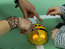
There already exists some similar solutions in the market, such as the Beebot (see image on the right). However, these solutions have very limited possibilites (you can program just the direction of the movement). For instance, they do not include any sensor, or other actuator but just a pair of wheels. This limit a lot the possibilities of the product. For children to develop computational thinking skills it is necessary that some actions can only be triggered by certain external events, and that is possible only using sensors.
Inspired by Beebot, in this project I am going to create a robot that can be programmed by pressing hardware buttons. In addition it will have a modular architecture, permitting the addition of one or two sensor modules that can be attached and dettached from the robot. These modules will have their own programming buttons. Finally, the robot will have a small LCD screen where children can visualize the actions that are gonna be executed when starting the robot.
Indoor irrigation system for plants
Problem description
I live in Oulu, but my home country is Spain. I try to travel there at least twice per year. I usually stay abroad around 10 days. My wife has a lot of plants at home, and we always need to bother a friend or a neighbour so he come often to water the plant while we are abroad. Another problem is that we need to place them close to a window so they get enough sun light (quite challenging during Finnish winter). Sometimes, we cannot place them in an adequate place so they do not receive enough light. That is the motivation of this idea.
Initial project proposal
I am planning to build an irrigation system that can be programmed to water the plants certain days of the weeks. I could also use some sensor to measure the humidity of the pot, and water the plant only when it needs it. It should be controlled somehow the amount of water distributed to each plant (each plant has different watering needs). I was planning to build an structure that allows placing a movable non-rigid pipe over the pot. A motor can move the end of the pipe to the right place so the water falls down in the right position. The pipe should be connected to a big bucket which stores the water.