2017
Iván Sánchez Milara

©2017 Iván Sánchez Milara | Template by Bootstrapious

This work is licensed under a Creative Commons Attribution-NonCommercial-ShareAlike 4.0 International License.
Final project. Design
Project design
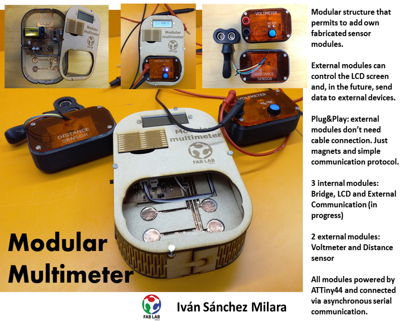
In this project I have built a modular multimeter. External measurements modules (e.g. voltmeter, light sensor, distance sensor, resistance sensor...) can connect to the main device via magnets and gain access to the LCD screen and, in the future, to external communication module able to send data to an external device. The main device will power the external modules with a 5V VCC. The main device is powered by a 9V battery. Different modules communicate with each other through asynchronous serial communication bus. External modules are always master devices in the communication. The external modules should implement a simple protocol in order to be able to send data to the LCD screen and to the external devices. In the main project page I define in more details the goal of the project and future work. In this page I will mainly focus on design and implementation aspects
Presentation video
Next you can find a video presentation of the project:
Existing work
I have been doing some research on similar existing work. Work is still in progress but I could not find that much related work.
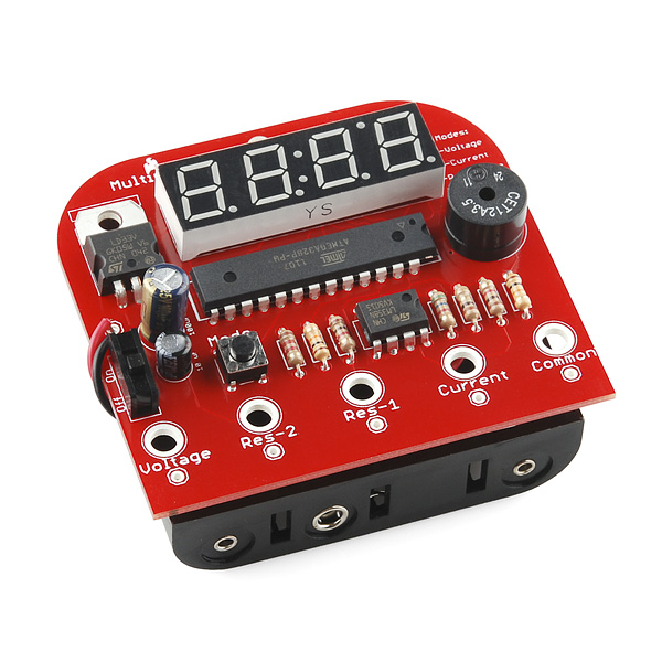
I found a DIY multimeter kit Sparkfun. This product provides a set of components and software to build your own multimeter capable of measuring voltage (0-30VDC, 0.05 resolution) current (0-500mA, 1mA resolution) and resistance (0-100kΩ). The resistance mode also includes a continuity.It is based on ATMega 328 processor
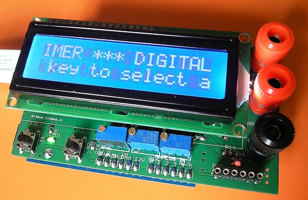
I also found a really interesting tutorial in Instructables that explains how to build your own multimeter shield for Arduino. The schematics and circuits provided in this tutorial have been very inspiring for my design.
Other inspiring projects for me has been the amazing IoT kit compatible with Lego created by Joris Lam at Fab Lab Amsterdam

Finally, a list of other projects and tutorials that I have been looking at and from which I got some ideas:
- Smart dice by Jonathan Bobrow
- Joog a music synt by James Fletcher
- HOw to build beatufil enclosures at Hackaday
- How to design snap-fit joints
Electronics and programming
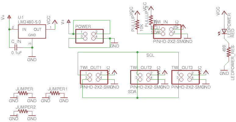
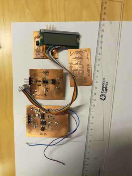
Main bridge
The bridge is the connection point of all the modules. It makes the network and power distribution. It is able of connecting 4 different modules (internal and external). Each connection contains four different lines: VCC (+5V), GND, Tx (send data from master, that is, external module, to rest of modules) and Rx to send data from slave modules to master (external measurement module). It also includes a LM3480IM3-5.0/NOPBCT-ND regulator that provides an output of 5V and a maximum current of 100mA. The device is powered with a 9V battery. The regulator is connected to an external switch which turns on - off the device.
Right now this module is just a physical bridge and does not have any microcontroller. The Tx and Rx can be used also as SDA and SCL lines for I2C communication. Actually, all modules use for the Tx and Rx the ATTiny44 pins reserved for SDA(PA6) and SCL (PA4). This board also has space to locate one pull up resistor in each line (as required for I2C) to be added in the future.
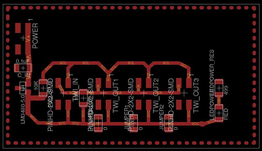
Circuits design
- Schematics and board file.
LCD module
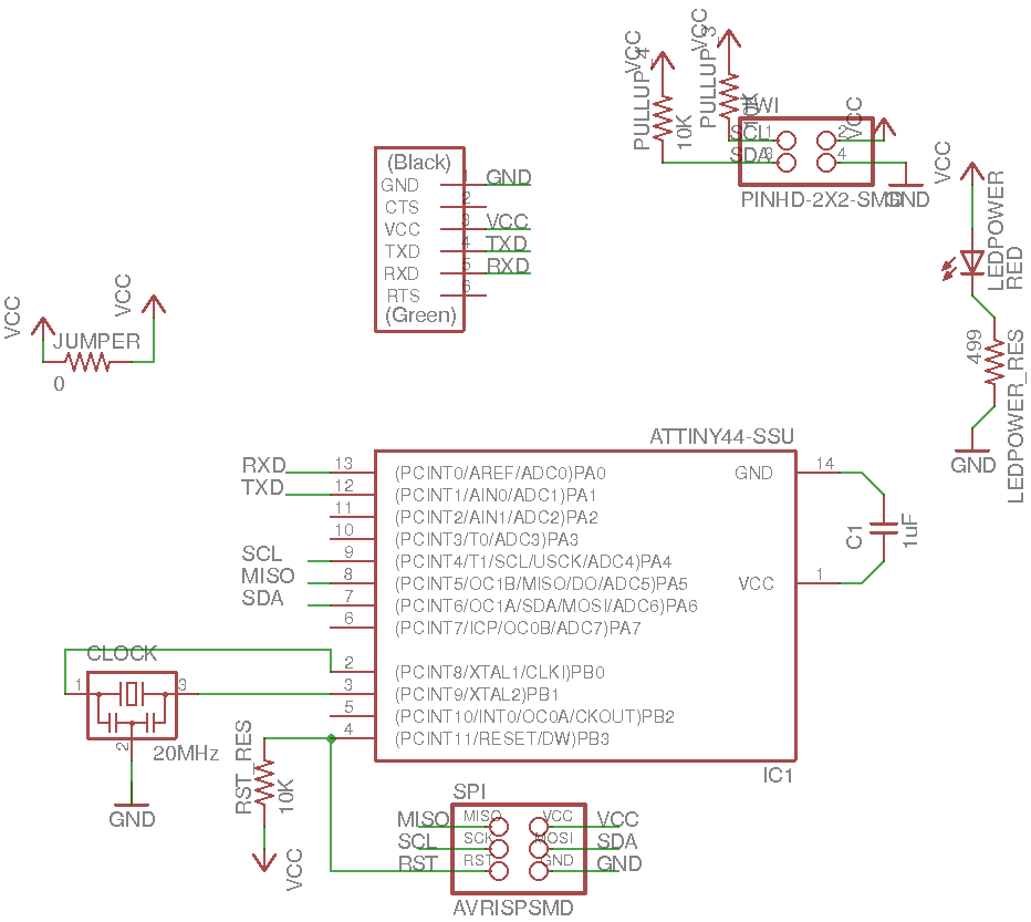
I took for the LCD module a small modification of the LCD board that I built for Output device assignment. I just remove all motors related components and added the adequate resistor that was missing from there. LCD requires at least 6 pins of the ATTiny44 (Enable, Instruction/Data and 4 data pins. In addition the module includes two networking pins for Asysnchronous Serial Communication (Tx -> PA4 and Rx -> PA6). Note that the LCD is a slave device so it receives data through the Tx pin and sends data through the Rx pin. It has also and FTDI port for debugging.

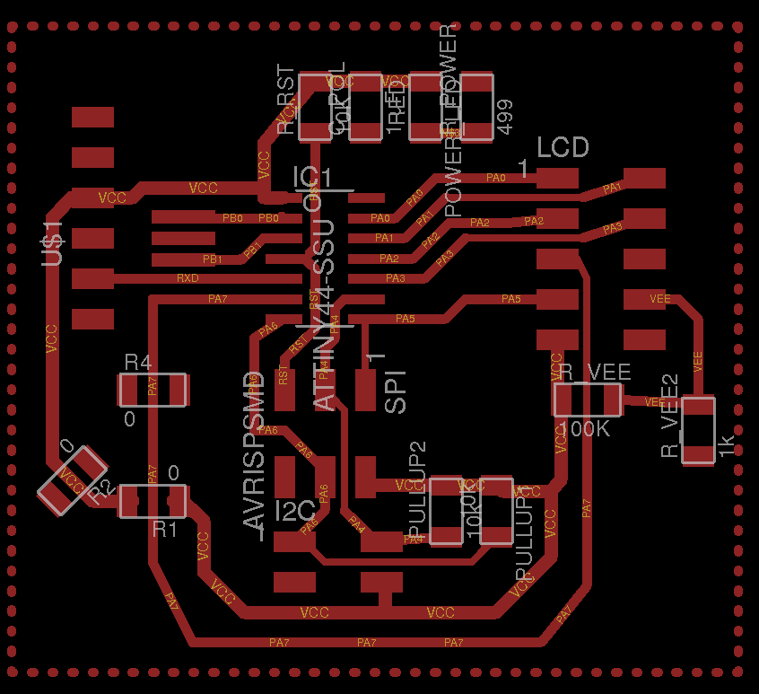
I did not use an external clock in this module. I just utilized the 8 Mhz internal clock. For settings the Fuses I utilized Raspberri Pi as a programmer as I did in week 8. Next, I check that the board programming interface is correct, and then I programmed the right fuses.
sudo avrdude -p t44 -P usb -C ./avrdude_gpip.conf -c rasp_pi_1 -v
[sudo] password for ivan:

avrdude: Version 6.2
         Copyright (c) 2000-2005 Brian Dean, http://www.bdmicro.com/
         Copyright (c) 2007-2014 Joerg Wunsch

         System wide configuration file is "./avrdude_gpip.conf"
         User configuration file is "/home/ivan/.avrduderc"
         User configuration file does not exist or is not a regular file, skipping

         Using Port                    : usb
         Using Programmer              : rasp_pi_1
         AVR Part                      : ATtiny44
         Chip Erase delay              : 4500 us
         PAGEL                         : P00
         BS2                           : P00
         RESET disposition             : possible i/o
         RETRY pulse                   : SCK
         serial program mode           : yes
         parallel program mode         : yes
         Timeout                       : 200
         StabDelay                     : 100
         CmdexeDelay                   : 25
         SyncLoops                     : 32
         ByteDelay                     : 0
         PollIndex                     : 3
         PollValue                     : 0x53
         Memory Detail                 :

                                  Block Poll               Page                       Polled
           Memory Type Mode Delay Size  Indx Paged  Size   Size #Pages MinW  MaxW   ReadBack
           ----------- ---- ----- ----- ---- ------ ------ ---- ------ ----- ----- ---------
           eeprom        65     6     4    0 no        256    4      0  4000  4500 0xff 0xff
           flash         65     6    32    0 yes      4096   64     64  4500  4500 0xff 0xff
           signature      0     0     0    0 no          3    0      0     0     0 0x00 0x00
           lock           0     0     0    0 no          1    0      0  9000  9000 0x00 0x00
           lfuse          0     0     0    0 no          1    0      0  9000  9000 0x00 0x00
           hfuse          0     0     0    0 no          1    0      0  9000  9000 0x00 0x00
           efuse          0     0     0    0 no          1    0      0  9000  9000 0x00 0x00
           calibration    0     0     0    0 no          1    0      0     0     0 0x00 0x00

         Programmer Type : linuxgpio
         Description     : Use the Linux sysfs interface to bitbang GPIO lines
         Pin assignment  : /sys/class/gpio/gpio{n}
           RESET   =  3
           SCK     =  14
           MOSI    =  4
           MISO    =  2

avrdude: AVR device initialized and ready to accept instructions

Reading | ################################################## | 100% 0.00s

avrdude: Device signature = 0x1e9207 (probably t44)
avrdude: safemode: hfuse reads as DF
avrdude: safemode: efuse reads as FF

avrdude: safemode: hfuse reads as DF
avrdude: safemode: efuse reads as FF
avrdude: safemode: Fuses OK (E:FF, H:DF, L:62)

avrdude done.  Thank you.
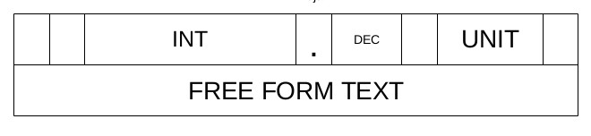
The LCD should show the following information:
- The measurement value: As a decimal number with a maximum of 6 integer values, a dot and two decimal number. It is shown in the first line.
- The measurement unit: as a maximum of three characters. It is shown in the first line after the measurement value
- A free form text: a maximum of 16 characters shown in the second line.
The commands to present data on the screen are described in more detail in the Output device's week. I will present here briefly how I have decided to present the measurement value, measurement unit and the free form text. The measure receives a float number
void write_measure(float measure) {
    char value [10]; //6 integers, dot and two decimals and end

    if (measure>999999){
      //Go to zero position
      lcd_putcmd(SHORT_DEFAULT_COMMAND);
      lcd_putcmd(SHORT_RETURNHOME);
      lcd_putchar(0x20); //space
          lcd_putstring("OVERFLOW");
      }
    //Negative number not supported
    else if (measure < 0) {
      //Go to zero position
      lcd_putcmd(SHORT_DEFAULT_COMMAND);
      lcd_putcmd(SHORT_RETURNHOME);
      lcd_putchar(0x20); //space
        lcd_putstring("   NEG   ");
    }
    else {
      //Go to zero position
      lcd_putcmd(SHORT_DEFAULT_COMMAND);
      lcd_putcmd(SHORT_RETURNHOME);
      lcd_putchar(0x20); //space
      char measure_char[10];
      unsigned int wholePart = measure;
      unsigned int fractPart = (measure - wholePart) * 100;
      sprintf(measure_char, "%i.%02i", wholePart, fractPart);
      //HERE SOME CODE TO ADJUST THE SPACES TO THE NUMBER OF DECIMALS. THEY SHOULD APPEAR CENTERED
      lcd_putstring(measure_char);
    }
}
The unit must be a 3 characters string. If unit is smaller, values are adjusted
void write_unit(char unit[]) {
  size_t size = strlen(unit);
    uint8_t cursor = 11;
    move_cursor_right(cursor, 1);

  if (size==1){
        lcd_putchar(unit[0]);
    lcd_putchar(20);
        lcd_putchar(20);

  }
  else if (size==2){

    lcd_putchar(unit[0]);
        lcd_putchar(unit[1]);
        lcd_putchar(20);


  }
    else if (size==3) {
    lcd_putchar(unit[0]);
        lcd_putchar(unit[1]);
        lcd_putchar(unit[2]);
  }

}
Free form text is written in the second line
void write_text(char text[]){
    //Change to second line line
     lcd_putcmd(SHORT_NEXT_LINE_1);
     lcd_putcmd(SHORT_NEXT_LINE_2);
     lcd_putstring(text);
}
The LCD is listening always in the Tx line checking for instructions. Network protocol is defined in the network section.
Circuits design and code
- Schematics and board file.
- lcd_test.c and lcd_test.c.make. Used for testing the board.
- lcd_measure.c and lcd_measure.c.make. Using for tesing that the LCD is able to show measureme distances.
- lcd.c and lcd.c.make. Final version of the code.
Communication Module
This module has just been designed in Eagle and I fabricated the board. However, since it is not a crucial component of the system I did not have time to finish it. Basically, it just has a network interface with the rest of the devices and a FTDI interface to communicate with an external device via USB. I have used an ATTiny44 to power the board.

Circuits design
- Schematics and board file.
External module: Voltmeter
Initially, my plans for the voltmeter were
- A voltemeter to measure voltages in 3 different scales: 6V, 10V and 20V. Each scale is implemented as a different voltage divider. The scale is selected using buttons, and controllerd by NMOS transistor (7 pins: 3 for the buttons, 3 for the MOSFET that controls the input, 1 for the measure).
- 3 LEDs to visualize the scale (3 pins)
- A 20MHz crystal that will be used as a clock (2 pins)
- Serial port (FTDI)to debug (2 pins)
- A network connection to communicate with other modules (2 pins)
The total number of available signal pins in ATtiny 44A is 11 (actually would be 12 but RESET should not be used as IO pin). With current design I would need 16 pins, so I need to reduce the number of pins. The new design is:
- A voltemeter to measure voltages in 2 different scales: 6V, 15V. The scale is selected using a single button, and controllerd by NMOS transistor (4 pins: 1 for the button, 2 for the MOSFETs that controls the input, 1 for the ADC input).
- 2 LEDs to visualize the scale. Controlled just with one pin.
- A 20MHz crystal that will be used as a clock (2 pins)
- Serial port (FTDI)to send data to external computer (2 pins)
- A network connection to communicate with other modules (2 pins)
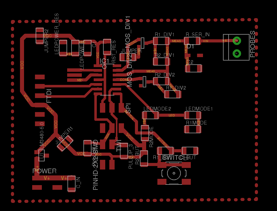
Next figures show the Eagle designs
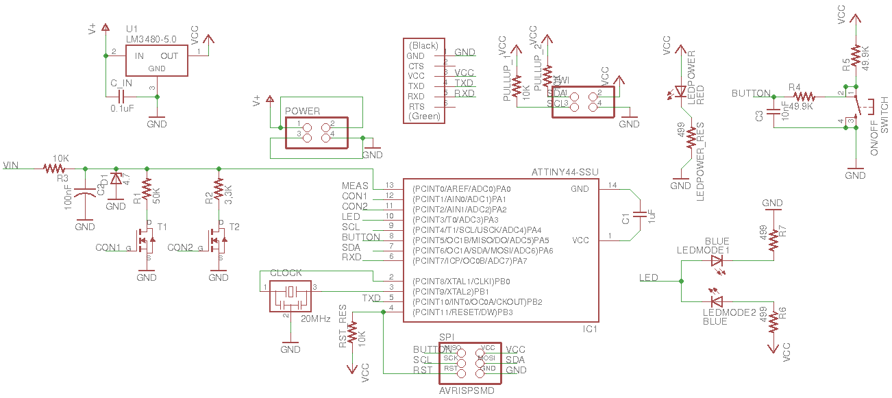
The voltmeter works as follows. I used the 10 bits ADC of the ATTiny 44 to measure the voltage coming from pin 13 (PA0). This will return a value between 0 (when the input is 0 V) and 1023 (when the input is 5 V). Since I have two different scales (6 V and 15 V), I need to create a voltage divider to be sure that when I insert in the input 6V or 20V I received in the microcontroller input pin (PA0) 5V. The transformation of voltage is then linear.
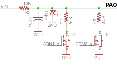
I decided to have an input resistor of 10K. Simple maths shows the value for the voltage divider for both scale.
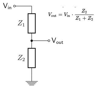
                  Vout = 5V
                  Z1 = 10K

                  For Scale 1:
                    Vin = 6V
                    Z2 = 50K

                  For Scale 2:
                    Vin = 20V
                    Z2 = 3.3K
Utilizing the resistors available in the Fab inventory we can have 50K utilizing two resistors of 100K in paralell, while I can get 3.3K with a resistor of 4.9K in parallel with other of 10K.
We need to be sure, that happen what happen, we cannot have more than 5V at the output of the voltage divider. To that end, I placed a Zener diode to limit the voltage at PA0. Initially, I used the diode in the Fab inventory (4.7V). However, I had big problems on measuring correctly at the end of the scale (close to 6 V and close to 20V). The problem is that the zener diode starts not to be linear close to the rupture voltage. Then I decided to use a slight bigger zener of 5.6 V.
In order to control which scale I am using, and hence, which voltage divider is in use, I utilized two N channel MOSFETs (RFD16N05LSM9ACT-ND ). The gate of each mosfet is connected to one pin, so the microcontroller can decide which is the voltage divider in use. It is very important that only one pin is open at the same time to receive correct values. A user can change the scale pressing the button connected to PA5. The button has its own debouncing circuit explained in more detail in the circuit design week.
I utilized two blue LEDs to indicate the current scale. The problem is that I had only one microcontroller pin available, so I managed to control two LEDs with just one signal (Figure 18). When the output pin is HIGH the LED at the top turns on, while when the output pin is LOW the LED at the bottom turns on. When the pin is in HIGH-Z then none of the pins turn on.

Regarding the code I will first explain how I am using the ADC and then how I did the measurement measure. For the ADC I used as a reference signal the VCC (that is 5V in the case of our circuit). The ADC should ruun on PA5 and I am not planning to use any autotriggering, that is, the code will have to implicictly say when I want to take a value. I will do that every time I go through the main loop. In addition, I need to preescale the clock. I am using a 20MHz clock frequency but the pproximation circuitry requires an input clock frequency between 50kHz and 200 kHz to get maximum resolution. Hence I decided to scale it by 128. Then I wanted to use right adjusted mode, that is that is, that ADCH registry contains the two more significant bits of the transformation while ADCL contains the less significant bits.
//INITIALIZING ADC
ADMUX = (0 << REFS1) | (0 << REFS0) | // Vcc ref (Table 16.3)
       (0 << MUX5)  | (0 << MUX4)  | (0 << MUX3)  | (0 << MUX2)  | (0 << MUX1)  | (1 << MUX0);  //Activate PA5/ADC5 (Table 16.4)


ADCSRA = 0x00;
ADCSRA = (1 << ADEN) | // enable ADC (16.13.2)
        (0 << ADATE) | // Disable autotriggering. Using single conversion mode.
        (1 << ADPS2) | (1 << ADPS1) | (1 << ADPS0); // prescaler /128
ADCSRB = 0x00; // (16.13.4)
ADCSRB = (0 << ADLAR); // Be sure that you have right adjusted mode
Whenever, I wanted to start a conversion I run the following code:
// initiate conversion
//
ADCSRA |= (1 << ADSC);
//
// wait for completion
//
while (ADCSRA & (1 << ADSC)) // while there is no 1 in ADCS no continue
  ;
//Read the value
measure = ADCL + 256*ADCH; // Read first ADCL and then ADCH
And then transforming the measure into an adequate voltage reading, I need to apply a simple transformation. Remember that I have two different scales:
if (current_scale ==1) // 6V scale
  measured_value = 6.0*measure/1023.0; //6V-> max Vin; 1023-> max value in ADC
else //20V scale
  measured_value = 20.1*measure/1023.0; //The maximum value given by the voltage divider is 20.1V. 20.1-> max Vin; 1023 -> max value in ADC
Finally, I need to serialize the measured_value, (type float), into 4 bytes so I can send it to the network. To do that, I am using a union. The most significant byte is sent first (big endian notation)
typedef union
{
    float f;
    uint8_t bytes[4];
} uFloatData;

...
uFloatData output;
output.f = measured_value; //Create the union;
uint8_t i=3;//the bytes[] array contains 4 elements (a serialized float)
//Send each byte of the union to the serial port.
do {
put_char(&serial_port, serial_pin_out, output.bytes[i]);
i--;
} while(i);
I noticed that the quality of the measurement depended a lot on the power source I am using since I am utilizing the VCC as voltage reference. When powering the circuit with FTDI cable, the readings varied a lot. However, the variation reduced dramatically when I connected a 9V battery. It went even better when I used our labs power sources. So, it is really important to know the quality of your input source. For future work, I might test using the internal 1.1 voltage reference coming from the ATTiny 44.
Circuits design and code
- Schematics and board file.
- test_volt_measure_serial.c and test_volt_measure_serial.c.make. Used for testing the board.
- voltmeter.c and voltmeter.c.make. Final version of the code.
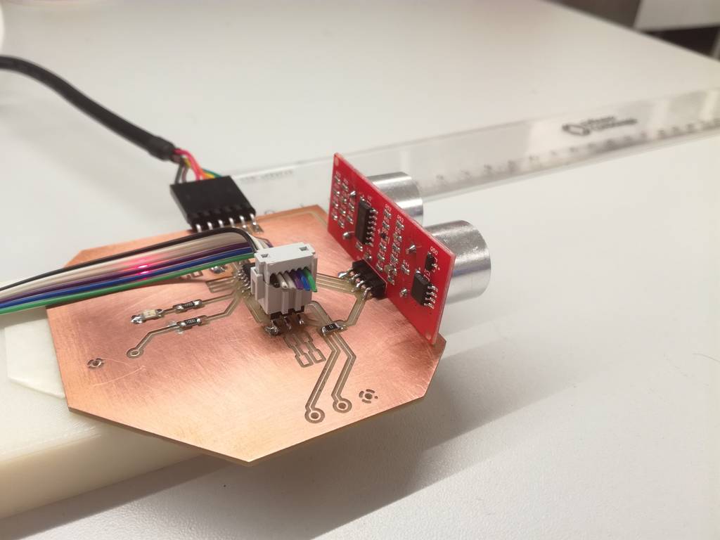
External module: distance sensor
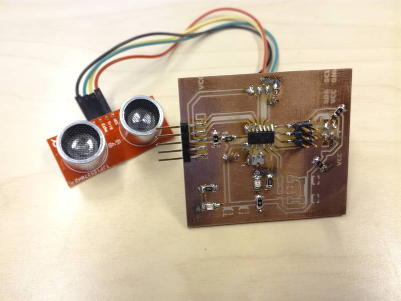
I will use a slightly modified version the distance sensor measurement I built for input devices assignment as a module. I made a little bit smaller, and remove certain functionality (e.g. the potentiometer and the buzzer). However, all details for the code and implementation can be found from the Week 13 assignment. During that week I utilized a Ultrasonic Module HC-SR04 Distance Sensor to measure distances. The same board was used during the Networking week to collect distance data and send it through the network. The code utilized for the final project is practically the same I used during that week. The same board was also used during the Interface and application programming assignment.

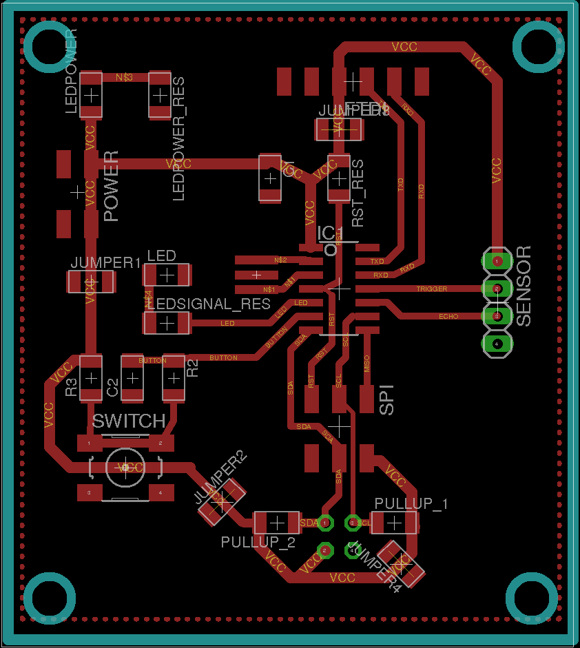
Circuits design and code
- Schematics and board file.
- test_distance_measure_serial.c and test_distance_measure_serial.c.make. Used for testing the board.
- distance.c and distance.c.make. Final version of the code.
Network
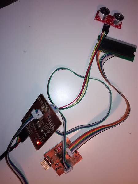
My initial intention was to utilize I2C protocol in order to connect the different modules with each other. However, during the Network week I explained the problems I had to include this protocol in my system. I did not have time to study the problems further. Hence, to connect the module I am using asynchronous serial communication. I have built a bus of 4 lines that make the power and network distribution. The lines are VCC,GND,TX (to send data from master to slave) and Rx(to send data from slave to master, currently not used). The external modules are always the master while the LCD and the external communication module will be the slaves. The speed is 9600bauds/second. Each frame is compose by a start bit (LOW, the data byte and a stop bit(HIGH))

I am using Neil's code from the week 15 to read and write data to the bus.
#define output(directions,pin) (directions |= pin) // set port direction for output
#define set(port,pin) (port |= pin) // set port pin
#define clear(port,pin) (port &= (~pin)) // clear port pin
#define bit_test(byte,bit) (byte & (1 << bit)) // test for bit set
#define bit_delay_time 102 // bit delay for 9600 with overhead  ~102 microseconds
#define bit_delay() _delay_us(bit_delay_time) // RS232 bit delay
#define half_bit_delay() _delay_us(bit_delay_time/2) // RS232 half bit delay
#define char_delay() _delay_ms(10) // char delay, before putting another character in the line.
//
// initialize output pins for serial ports
//
set(serial_port, serial_pin_out);
output(serial_direction, serial_pin_out);//Set TX output to HIGH

void put_char(volatile unsigned char *port, unsigned char pin, char txchar) {
   //
   // send character in txchar on port pin
   //    assumes line driver (inverts bits)
   //
   // start bit
   //
   clear(*port,pin);
   bit_delay();
   //
   // unrolled loop to write data bits
   //
   if bit_test(txchar,0)
      set(*port,pin);
   else
      clear(*port,pin);
   bit_delay();
   if bit_test(txchar,1)
      set(*port,pin);
   else
      clear(*port,pin);
   bit_delay();
   if bit_test(txchar,2)
      set(*port,pin);
   else
      clear(*port,pin);
   bit_delay();
   if bit_test(txchar,3)
      set(*port,pin);
   else
      clear(*port,pin);
   bit_delay();
   if bit_test(txchar,4)
      set(*port,pin);
   else
      clear(*port,pin);
   bit_delay();
   if bit_test(txchar,5)
      set(*port,pin);
   else
      clear(*port,pin);
   bit_delay();
   if bit_test(txchar,6)
      set(*port,pin);
   else
      clear(*port,pin);
   bit_delay();
   if bit_test(txchar,7)
      set(*port,pin);
   else
      clear(*port,pin);
   bit_delay();
   //
   // stop bit
   //
   set(*port,pin);
   bit_delay();
   //
   // char delay
   //
   bit_delay();
   }

void get_char(volatile unsigned char *pins, unsigned char pin, char *rxbyte) {
   //
   // read character into rxbyte on pins pin
   //    assumes line driver (inverts bits)
   //
   *rxbyte = 0;
   while (pin_test(*pins,pin))
      //
      // wait for start bit
      //
      ;
   //
   // delay to middle of first data bit
   //
   half_bit_delay();
   bit_delay();
   //
   // unrolled loop to read data bits
   //
   if pin_test(*pins,pin)
      *rxbyte |= (1 << 0);
   else
      *rxbyte |= (0 << 0);
   bit_delay();
   if pin_test(*pins,pin)
      *rxbyte |= (1 << 1);
   else
      *rxbyte |= (0 << 1);
   bit_delay();
   if pin_test(*pins,pin)
      *rxbyte |= (1 << 2);
   else
      *rxbyte |= (0 << 2);
   bit_delay();
   if pin_test(*pins,pin)
      *rxbyte |= (1 << 3);
   else
      *rxbyte |= (0 << 3);
   bit_delay();
   if pin_test(*pins,pin)
      *rxbyte |= (1 << 4);
   else
      *rxbyte |= (0 << 4);
   bit_delay();
   if pin_test(*pins,pin)
      *rxbyte |= (1 << 5);
   else
      *rxbyte |= (0 << 5);
   bit_delay();
   if pin_test(*pins,pin)
      *rxbyte |= (1 << 6);
   else
      *rxbyte |= (0 << 6);
   bit_delay();
   if pin_test(*pins,pin)
      *rxbyte |= (1 << 7);
   else
      *rxbyte |= (0 << 7);
   //
   // wait for stop bit
   //
   bit_delay();
   half_bit_delay();
   }
The Network week assignment provided a detailed description of the protocol utilized and the implementation of such protocol. In brief, each device is identified by a network address known by all members of the network beforehand (no address discovery). The master can send different commands to the network that will be listened just by the defined targets. Some commands requires a payload. The protocol is summarized in Figure 25:
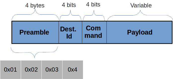
- Preamble: It consists of 4 bytes, which value are
0x01, 0x02, 0x03, 0x04 - Destination address: It consists of 4 bits (half byte). The address space would be then 16 devices. However, in order to avoid that any of the preamble bytes coincide with any possible address, the initial bit is always 1, reducing the address space to 8 devices. Enough for this project.
- Command: It consists of 4 bits. Possible values:
- 0x00: WRITE_VALUE: Writes a distance value in the LCD screen. Its payload has a fixed size of 4 bytes. Actually, the payload should be a float serialized to 4 bytes using big endian notation.
- 0x01: WRITE_UNIT: Modifies the unit. The distance module must send a string containing the new unit. The payload has a fixed lenght of 3 bytes.
- 0x02: WRITE_TEXT: Writes any text in the lower line of the LCD screen. The payload has a variable lenght. The first byte of the payload indicates such length
- Payload: Depending on the command the size might be fixed or variable. If the payload has a varaible size, the first byte of the payload indicates such lenght.
Next I will show an example on how to send the command WRITE_UNIT. In this case the payload has fixed length:
static  const uint8_t WRITE_VALUE = 0;
static  const uint8_t WRITE_UNIT = 1;
static  const uint8_t WRITE_TEXT = 2;

#define screen_id 8
#define serial_id 9
void send_unit(char unit []) {
     output(serial_direction, serial_pin_out);
     //Preamble
   put_char(&serial_port, serial_pin_out, 1);
   put_char(&serial_port, serial_pin_out, 2);
     put_char(&serial_port, serial_pin_out, 3);
     put_char(&serial_port, serial_pin_out, 4);
     //Send command
     uint8_t command = screen_id << 4 | WRITE_UNIT;
     put_char(&serial_port, serial_pin_out, command);

     put_char(&serial_port, serial_pin_out, unit[0]);
     put_char(&serial_port, serial_pin_out, unit[1]);
     put_char(&serial_port, serial_pin_out, unit[2]);
     //HIGH-Z
     input(serial_direction, serial_pin_out);
}
And next, an example on how to process the data. Note that if the receiver node is not the target, it does not read the payload. This is an example of the LCD mddule
static  const uint8_t WRITE_VALUE = 0;
static  const uint8_t WRITE_UNIT = 1;
static  const uint8_t WRITE_TEXT = 2;

#define screen_id 8
  int process_frame(){
    uint8_t byte1=0, byte2=0, byte3=0, byte4=0, command =0;
    //Search the start of the frame
    while (1) {
    byte1 = byte2;
    byte2 = byte3;
    byte3 = byte4;
    byte4 = command;
    uint8_t byte1=0, byte2=0, byte3=0, byte4=0, command =0;
    //Search the start of the frame
    while (1) {
      byte1 = byte2;
      byte2 = byte3;
      byte3 = byte4;
      byte4 = command;
      get_char(&serial_pins, serial_pin_in, &command);
          if ((byte1 == 1) & (byte2 == 2) & (byte3 == 3) & (byte4 == 4)){
            //Preamble found
            //Reset the preamble.
            byte1=byte2=byte3=byte4=0;
            //Process the rest of the bits.
            break;

          }
    }
    // Analyze the id. If it is not the the own id, do not process anymore.
    uint8_t id = command >> 4;
      if (id != noden_id) {
        //If it is not targeted to this node do not process more and find again the preamble.
        return;
      }
    //If it is the right address check the command.
    command = command & 0x0F;

   //If command is WRITE_UNIT
    if (command == WRITE_UNIT) {
      char units [4];
      uint8_t i;
      for (i=0; i < 3; i++){
         get_char(&serial_pins, serial_pin_in, &units[i]);
      }
      units[3]=NULL;
      write_unit(units); //Write the measurement unit on the screen.
    }
    ....//PROCESS THE REST OF THE COMMANDS
}
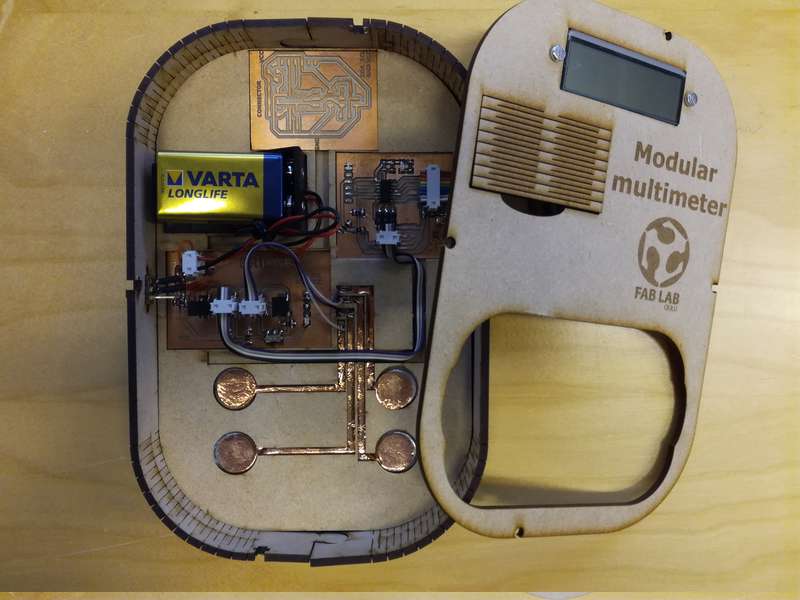
Main case
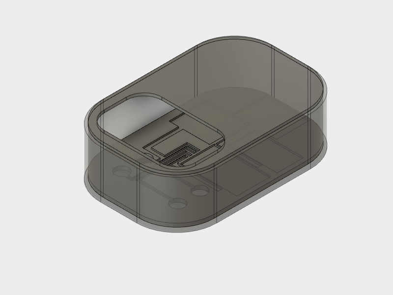
My initial idea was to have an outer box, which contains the internal modules (LCD, bridge and communication module) and is able to accomodate two external modules. I was planning to use magnets in order to keep the external modules attached to the main case. When I start building the case I spend some time to find the best way of making the connection easily, preferably without the need of cables. I start sketching with paper how could I accomodate all the boards. Quickly I realized that the size of the device was going to be very big if I wanted to include two external module, so I decided to utilize just one external module.
I made a 3D model of the case using Autodesk fusion 360. I won't print the case in 3D but at least, it would give me a nice idea of the right dimensions.The model can be obtained from the Models repository below.
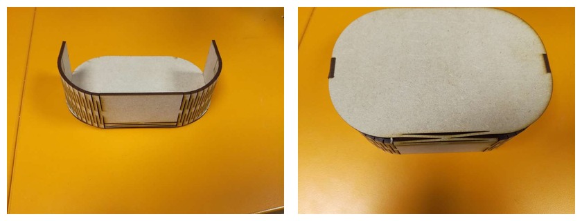
After defining the dimensions with the 3D model, next step is thinking what type of box did I want. I thought that the case was going to look more appealing if I cut it from wood. I wanted to have just two parts' box. On one side the lid and on the other the bottom and the walls. Hence, I need to fold the wood utilizing living hinges. I had to design two types of living hinges, perpendicular one to another. The first one allows the curvature of the lateral walls while the second ones permits rising the walls from the box's bottom. The bottom would be a rectangle with round corners, which allows enough curvature for the living hinge to fold enough. I decided to use a 3mm MDF stock for the board.
Calculating the length of the living hinge area so it folds with certain radius is not trivial. Furthermore, the length of the cuts and the separation among them must also be considered. These figures depends a lot on the material composition and its thickness. The kerf of the laser should also be considered. I found some formulas in the blog "Deferred Procrastination". Exactly I have used this post, this post and this one. Basically, I want to create Lattice Hinge as shown on Figure 29

The number of connections and the length of each connection is given by the following formula:

In addition the bent radius and the arc lenght of the bend are related with the following formulas. Note that I had to do small corrections to the formula given in the blog, basically I just removed a 2.
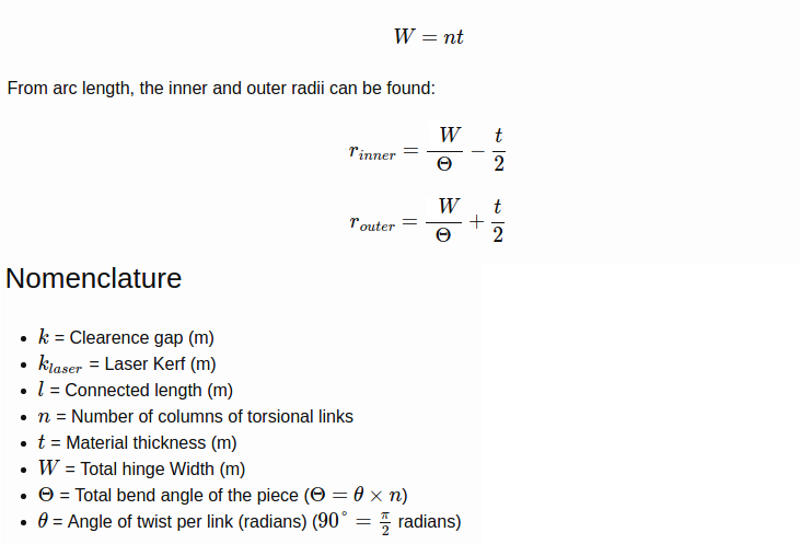
Based on this information, knowing that the corner radius is 42 mm, and taking the MDF physical properties from this site
Although the box looks consistent, I would like to try with other materials. Next test will be with a 4mm plywood. I can try also with acrylic, although I am not very convinced that it has enough flexibility so I am able to cut the board in just two pieces. We get the following data:

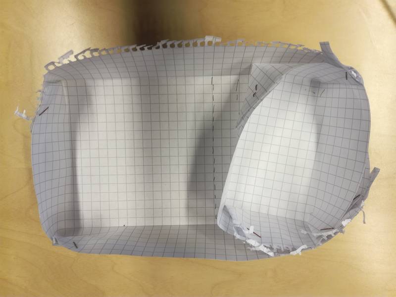
Based on this calculus I got that I should have 23 links for an MDF of 3mm if we want to have a radius of 42mm. This turned out to be a really nice approximation and it was the one I used for the final version of the box. The problem now was to calculate which was the correct parameters for the hinge that rises the walls (that is, the one which connects the bottom surface with the walls. To calculate the parameters I did multiple tests (Figure 33)
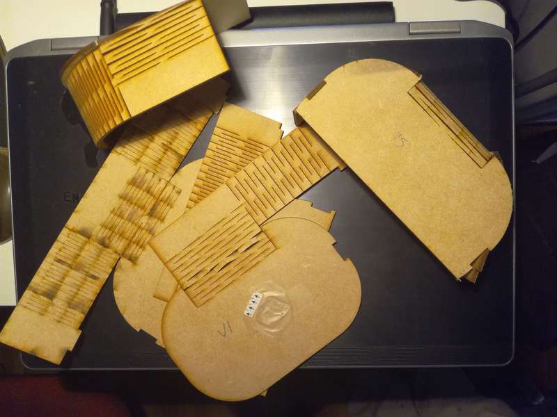
The main problem was that if I utilize a big radius, the wall elevates a lot leaving a space between the bottom surface and the wall (Figure 34)
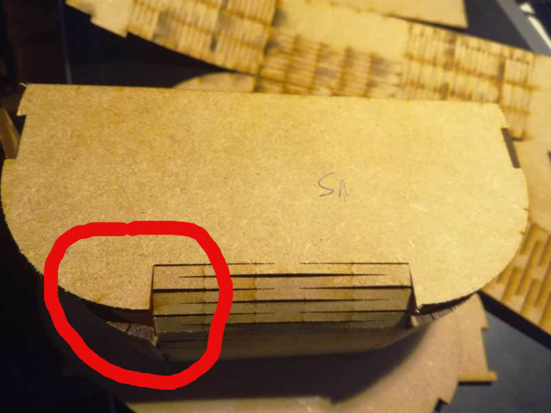
The best solution was to have an abrupt elevation. Just two connections of the hinge at the bottom turned out to be a good solution. The material had to support a lot of stress, but since the hinges have enough length it can support it.
After that, I just used Inkscape to draw the model to cut. The lateral walls were connected through tabs to the bottom. Both walls were connected through circular tabs. I considered a kerf of 0.20 mm to make the tabs. The pieces were connected through press-fit. I draw some holes to insert a captive nut in the wood, and hence connect the lid with the box utilizing nuts and bolts. In addition, I had to draw a slot for the on/off switch.

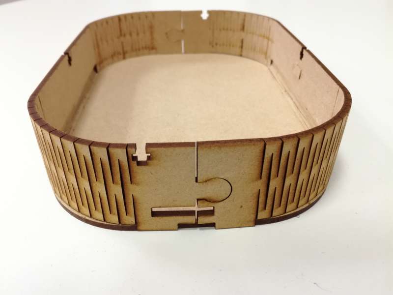
The lid has a living hinge used as a cover for the batteries. In addition it contained a hole to host the external modules and another one to attach the LCD screen.
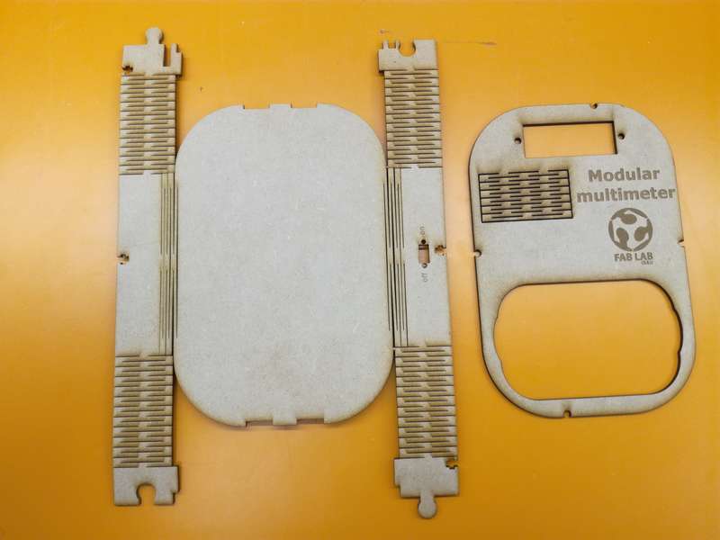
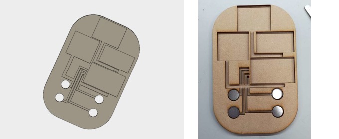
I laser cut also a 3mm MDF as a placeholder for the PCBs and connection cables. It contains slots to hosts the boards, the cables, and the metals to snap the external modules magnets. It was glued to a 3mm MDF cut with the same shape of the box's bottom. Hence, the floor of the box had a total thickness of 9mm.
In order to connect the external modules to the main bridge I cut with the vynil cutter a two-sided copper film to make the traces that connects the magnents placeholder with the bridge board. Each magnet placeholder transmit a different signal: VCC, GND, Tx and Rx. The cables were directly soldered to the copper tracks. Glueing the tracks to the placeholder was a tedious task. I made track by track after soldering the cables. It was definitively not the easiest way. Perhaps, soldering after attaching the tracks would have been easier. In addition, I think next time I will try to stick all the tracks at once, as a whole piece instead of track by track.
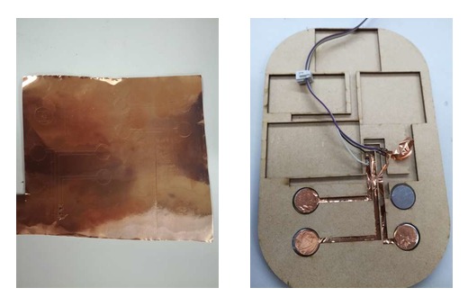
Finally, I glued with two sided tape the boards to the placeholder. The cables were glued with hot glue. I tried to reduce at maximum the size of the cables.
2D and 3D models
- Fusion 360 case file
- External box case to laser cut
- Floor traces, to be glued on Floor structure
- Floor structure
- Main cover
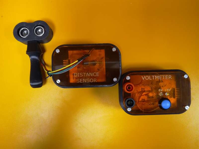
External module cases
The cases for the two external modules (Voltmeter and Distance measurement) were 3D printed using ABS. The cover were cut out of 3mm semitransparent orange acrylic. In addition for the Distance module I designed a cover to handle easier the sensor module.
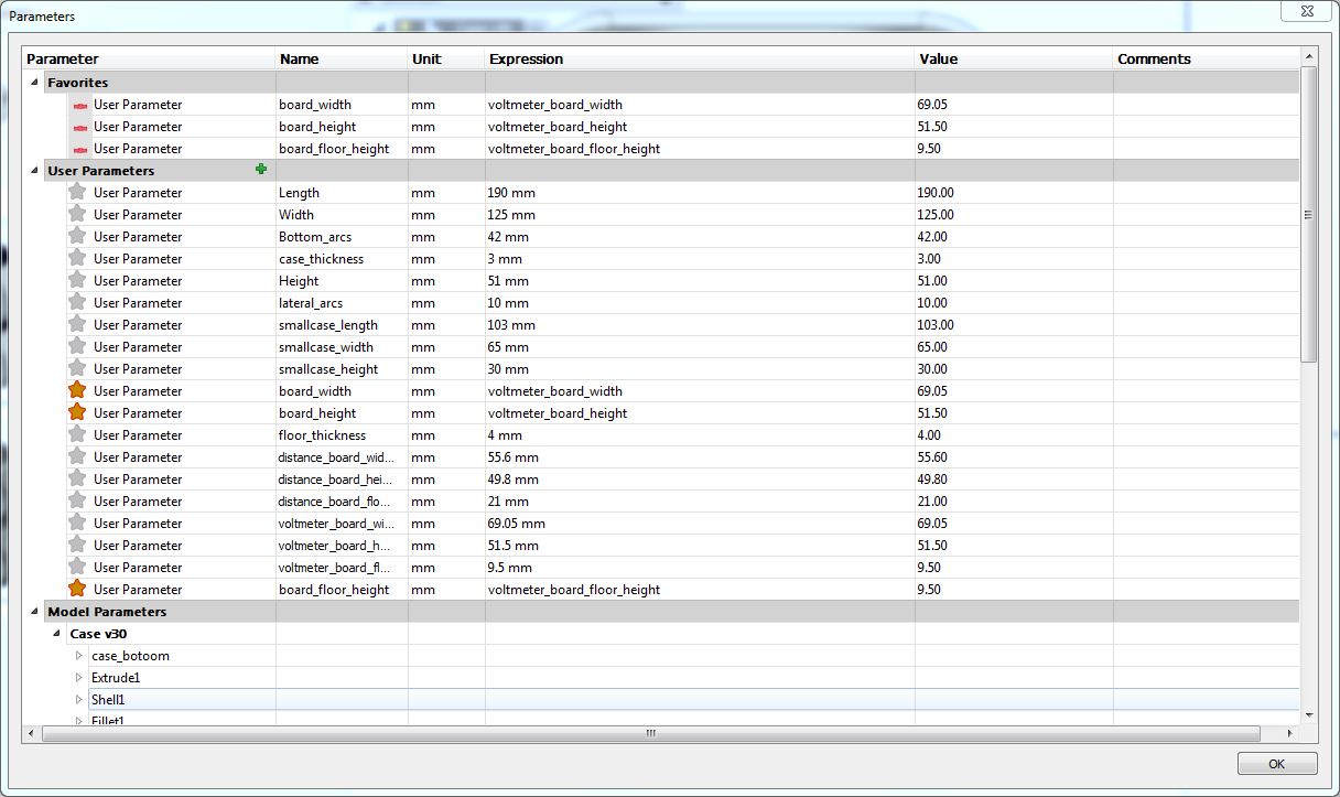
I built the case with Fusion 360 and using parametric design. The boards were built basically as rectangular boxes to which I added later a fillet in the bottom and lateral edges and a chamfer at the top edge. I made 4 holes for M3 screws in order to screw the box cover. In addition I made a placeholder for the box. Moreover, I made 4 circular legs at the bottom with a slot to insert the circular magnets. In additon, I made a hole in each leg to insert PCB signal cables. Finally, I made a small square hole for cables in one of the walls as a back up plan in case that the connection using magnets did not work.

I used several paramters in order to define the dimensions of the external cases. For instance modifying the parameters board_width, board_length and board_height we can modify the internal placeholder to locate the board. This design permits to build easily a case that adapts to any box.
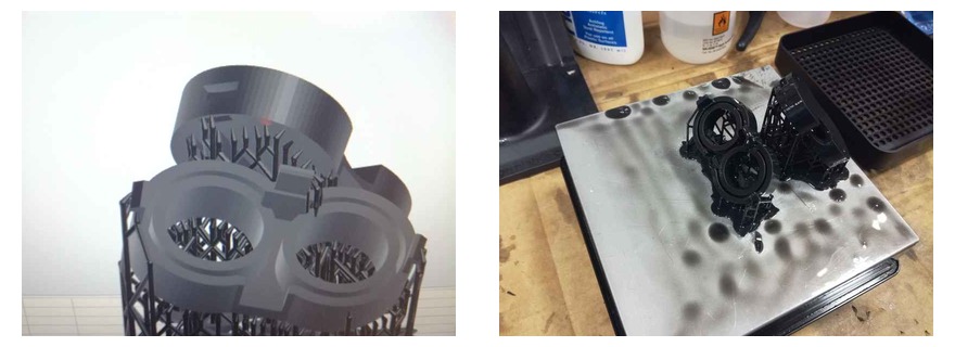
I printed both pieces with a Stratasys Fortus 380mc utilizing ABS. Printing took 4 hours, while removing the support material took 48 hours inserted in caustic soda.


Initially, I set a fillet of 40 mm at the bottom edge. The printer could not managed it and let areas without placing material, leaving certain slots (Figure 47). I modified the fillet and changed to 10mm

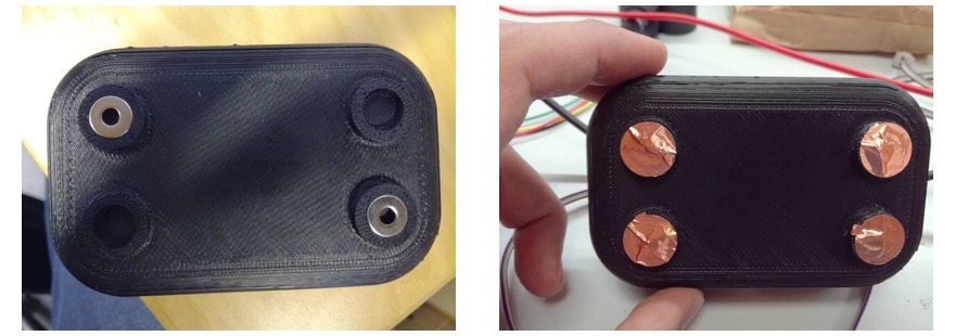
Once the piece was 3d printed I utilized a thread tool to mark the bolt thread in the ABS (Figure 48)

After that I had to add one of the four bus signals VCC, GND, Tx and Rx to each one of the legs. First I placed one circular magnet in each leg (Figure 49 left). Observe that I used magnets with holes so cables can go through them. I did not add any glue to the magnets they perfectly press fit on the reserved slots. After placing the magnets, I soldered to the end of the bus cables a circular copper film. Then glue the circles into the magnets and the leg as shown in Figure 49 (right). The idea is that the magnets make enough force so both copper films (the one from the external module and the one from the main case) make good contact.
I followed the same process for both boxes.
Voltmeter case
The voltmeter case was completed after adding the cover (cut out of 3mm semitransparent orange acrylic). The cover includes holes for a button (to change the scale), two blue LED which indicates the current scale and the connections for the probes. For the button I used a Bulgin MMP0120/ABLS with a screw terminal connection. For the probes connector I utilized a banana jack panel mount connector. None of the two previous components were in the Fab inventory. To connect the banana jack to the board I utilized a 3.5mm terminal block of two positions (see Figure 51). Figure 52 shows the external module finished while Figure 53 shows the module integrated in the case.


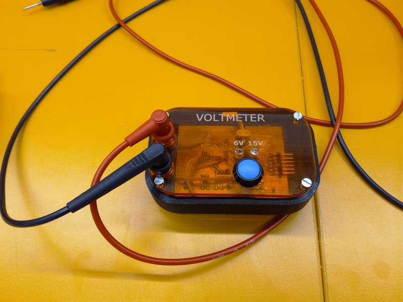

The external module attach perfectly to the main case. I had to add two more layer of copper film in one of the legs, since it did not do good contact. I do not know if one of the legs is a little bit shorter than the other or that the bottom of the main case is a little bit bent. However, after adding the extra layer of copper film, the connections worked properly.
Distance sensor case
For the ditance sensor module I built a cover for the ultrasonic sensor so it can be grabbed easily. The whole module is shown in Figure 54
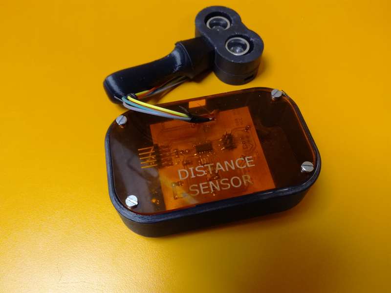
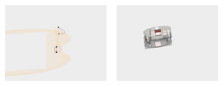
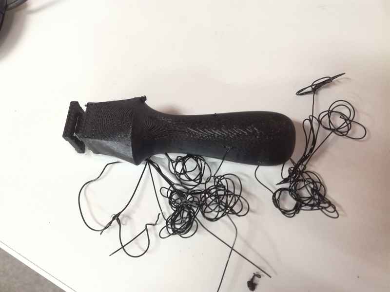
To build the case for the ultrasonic sensor module I used Fusion 360. The case was composed by three parts: back cover, front cover and handle. The back cover and front cover were joined together through a Cantilever snap fit join. The handle is supported by the two previous pieces. I utilized a FormLabs Form2 printer to print the back and front cover, while I utilized the Stratasys Fortus 380mc to print the handle. I utilized this model of the HC-SR04 ultrasonic sensor coming from GrabCAD in order to model the case. The file is included in my repo.

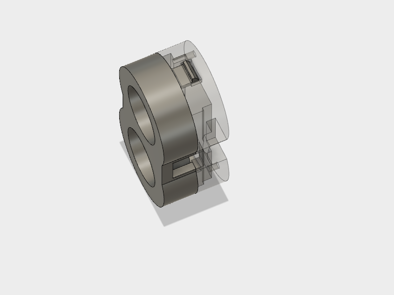
I made a big mistake while designing the cantilever snap fit joints. I made a very small hole. Actually, I just considered for the hole size the thicknes of the snap fit joint, but I did not take into account the thickness of the head. I had to sand a lot the head of the 3 snap fit joints so they fit correctly in the holes.

2D and 3D models
- Fusion 360 cases file. Check the case components
- voltmeter's and distance module's .stl design
- voltmeter's and distance module's cover
- Fusion 360 ultrasound module's cover file.
- Ultrasound module's cover: Front, Back and Handle
- Model of the HC-SR04 obtained from GrabCAD
BILL OF MATERIALS
The total cost of the system, without including materials (MDF, acrylic, ABS) is 55.92€. The BOM is presented next. Note that all prices are in Euros (€). The cost of each board is provided separately. Material price is not quantized, however, I have estimated the amount of material needed for each part.
| A | B | C | D | E | F | |
|---|---|---|---|---|---|---|
1 | LCD board | |||||
2 | Quantity | Value | Device | Price/unit | Price total | NOTES |
3 | 1 | PINHD-2X2-SMD | 0.66 | 0.66 | ||
4 | 1 | PINHD-2X5-SMD | 0.89 | 0.89 | ||
5 | 3 | 0 | RES-US1206FAB | 0 | 0 | |
6 | 1 | 1 uF | CAP-UNPOLARIZEDFAB | 0.07 | 0.07 | |
7 | 1 | 100K | RES-US1206FAB | 0.01 | 0.01 | |
8 | 1 | 10K | RES-US1206FAB | 0.01 | 0.01 | |
9 | 2 | 10k | RES-US1206FAB | 0.01 | 0.02 | |
10 | 1 | 1k | RES-US1206FAB | 0.01 | 0.01 | |
11 | 1 | 499 | RES-US1206FAB | 0.01 | 0.01 | |
12 | 1 | ATTINY44-SSU | 1.18 | 1.18 | ||
13 | 1 | AVRISPSMD | 0.6 | 0.6 | ||
14 | 1 | FTDI-SMD-HEADER | 0.55 | 0.55 | ||
15 | 1 | RED | LEDFAB1206 | 0.13 | 0.13 | |
16 | 1 | LCDMODULE | 7.06 | 7.06 | ||
17 | 1 | 20MHZ | RESONATOR | 0.43 | 0.43 | |
18 | ||||||
19 | TOTAL | 11.63 | ||||
20 | BRIDGE board | |||||
21 | 1 | PINHD-2X2-SMD | 0.66 | 0.66 | ||
22 | 3 | 0 | RES-US1206FAB | 0 | 0 | |
23 | 1 | 0.1uF | CAP-UNPOLARIZEDFAB | 0.12 | 0.12 | |
24 | 2 | 10K | RES-US1206FAB | 0.01 | 0.02 | |
25 | 1 | 499 | RES-US1206FAB | 0.01 | 0.01 | |
26 | 1 | LM3480-5.0 | 0.32 | 0.32 | ||
27 | 4 | PINHD-2X2-SMD | 0.66 | 2.64 | ||
28 | 1 | RED | LEDFAB1206 | 0.13 | 0.13 | |
29 | ||||||
30 | TOTAL | 3.9 | ||||
31 | ||||||
32 | VOLTMETER board | |||||
33 | 2 | NMOSFETSOT23 | 0.26 | 0.52 | ||
34 | 1 | PINHD-2X2-SMD | 0.66 | 0.66 | ||
35 | 3 | 0 | RES-US1206FAB | 0 | 0 | |
36 | 1 | 0.1uF | CAP-UNPOLARIZEDFAB | 0.12 | 0.12 | |
37 | 2 | 100K | RES-US1206FAB | 0.01 | 0.02 | |
38 | 1 | 100nF | CAP-US1206FAB | 0.04 | 0.04 | |
39 | 5 | 10K | RES-US1206FAB | 0.01 | 0.05 | |
40 | 1 | 10nF | CAP-UNPOLARIZEDFAB | 0.04 | 0.04 | |
41 | 1 | 1uF | CAP-UNPOLARIZEDFAB | 0.07 | 0.07 | |
42 | 1 | 20MHz | RESONATOR | 0.43 | 0.43 | |
43 | 1 | 5.6V | ZENER_DIODESOD123 | 0.07 | 0.07 | |
44 | 1 | 4.9K | RES-US1206FAB | 0.01 | 0.01 | |
45 | 2 | 49.9K | RES-US1206FAB | 0.01 | 0.02 | |
46 | 3 | 499 | RES-US1206FAB | 0.01 | 0.03 | |
47 | 1 | ATTINY44-SSU | 1.18 | 1.18 | ||
48 | 1 | AVRISPSMD | 0.6 | 0.6 | ||
49 | 2 | BLUE | LEDFAB1206 | 0.13 | 0.26 | |
50 | 1 | FTDI-SMD-HEADER | 0.55 | 0.55 | ||
51 | 1 | PINHD-2X2-SMD | 0.66 | 0.66 | ||
52 | 1 | RED | LEDFAB1206 | 0.13 | 0.13 | |
53 | 1 | TERM-1X02-FABLAB | 0.42 | 0.42 | ||
54 | ||||||
55 | TOTAL | 5.88 | ||||
56 | ||||||
57 | DISTANCE SENSOR board | |||||
58 | 1 | PINHD-1X4 | 0.66 | 0.66 | ||
59 | 1 | PINHD-2X2 | 0.66 | 0.66 | ||
60 | 1 | PINHD-2X2-SMD | 0.66 | 0.66 | ||
61 | 4 | 0 | RES-US1206FAB | 0 | 0 | |
62 | 3 | 10K | RES-US1206FAB | 0.01 | 0.03 | |
63 | 1 | 10nF | CAP-UNPOLARIZEDFAB | 0.04 | 0.04 | |
64 | 1 | 1uF | CAP-UNPOLARIZEDFAB | 0.07 | 0.07 | |
65 | 1 | 20MHz | RESONATOR | 0.43 | 0.43 | |
66 | 2 | 49.9K | RES-US1206FAB | 0.01 | 0.02 | |
67 | 2 | 499 | RES-US1206FAB | 0.01 | 0.02 | |
68 | 1 | ATTINY44-SSU | ATTINY44-SSU | 1.18 | 1.18 | |
69 | 1 | AVRISPSMD | AVRISPSMD | 0.6 | 0.6 | |
70 | 1 | FTDI-SMD-HEADER | FTDI-SMD-HEADER | 0.55 | 0.55 | |
71 | 1 | RED | LEDFAB1206 | 0.13 | 0.13 | |
72 | 1 | YELLOW | LEDFAB1206 | 0.1 | 0.1 | |
73 | 1 | Ultrasonic Module HC-SR04 | 8.99 | 8.99 | ||
74 | 0 | |||||
75 | TOTAL | 14.14 | ||||
76 | ||||||
77 | MAIN CASE | |||||
78 | 4 | M3 x10 mm | Bolts | 0.06 | 0.24 | |
79 | 4 | M3 | Nuts | 0.04 | 0.16 | |
80 | 442 | MDF x 3mm | Main box | 0 | Unit: cm2 | |
81 | 228 | MDF x 3mm | Cover | 0 | Unit: cm2 | |
82 | 456 | MDF x 3mm | Components placeholder | 0 | Unit: cm2 | |
83 | 3 | 2x2 | Headers for network cable | 0 | ||
84 | Connector cable | 0 | ||||
85 | ||||||
86 | TOTAL | 0.4 | ||||
87 | ||||||
88 | EXTERNAL MODULES | |||||
89 | 53.084 | ABS | Case 1 | 0 | Unit: cm3 | |
90 | 53.084 | ABS | Case 2 | 0 | Unit: cm3 | |
91 | 17.075 | ABS | Handle | 0 | Unit: cm3 | |
92 | 15.468 | Support material | Case 1 | 0 | Unit: cm3 | |
93 | 15.468 | Support material | Case 2 | 0 | Unit: cm3 | |
94 | 8.249 | Support material | Handle | 0 | Unit: cm3 | |
95 | 56.48 | Acrylic x3 mm | Case 1 | 0 | Unit: cm2 | |
96 | 56.48 | Acrylic x3 mm | Case 2 | 0 | Unit: cm2 | |
97 | Copper film two sides | 0 | ||||
98 | 8 | M3 x10 mm | Bolts | 0.06 | 0.48 | |
99 | 8 | Neodym-magneetti | 0.7 | 5.6 | NOT in Fabinventory | |
100 | 1 | SWITCH PUSHBUTTON SPST-NO | 6.67 | 6.67 | NOT in Fabinventory | |
101 | 2 | BANANA JACK PANEL MNT | 3.39 | 6.78 | NOT in Fabinventory | |
102 | 2 | BLUE | LED5MM ROUND T/H | 0.22 | 0.44 | NOT in Fabinventory |
103 | ||||||
104 | TOTAL | 19.97 | ||||
105 | ||||||
106 | ||||||
107 | SYSTEM TOTAL | 55.92 | ||||