final project
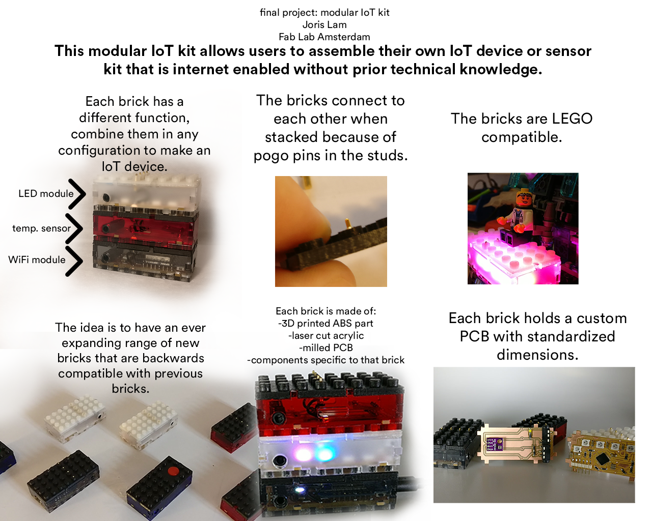
For my final project I have made a series of modular connected LEGO-like bricks that can be used to make IoT devices. Each brick has a different function in a system that users can build themselves without prior technical knowledge.The goal for my final project is to create a proof of concept for this system that I can expand on and develop further after Fab Academy.
Please find the slide here and the video here.
INDEX
1 - PROJECT MANAGEMENT
2 - SYSTEM & COMMUNICATION
3 - PCB DESIGN PART 1
4 - BACK TO THE DRAWING BOARD
5 - COMPLETING FIRST SPIRAL
6 - 3D design and printing
7 - LASER CUTTING
8 - FIRST ASSEMBLY
9 - MAKING MORE BRICKS
10 - LED BRICK
11 - PROGRAMMING BOARD
12 - I2C COMMUNICATION
13 - SENSOR BRICK
14 - CODE
15 - FINAL ASSEMBLY
16 - WIP
17 - IMPROVEMENTS AND CONCLUSION
18 - BILL OF MATERIALS
19 - APPLICATIONS AND IMPLICATIONS
20 - DISSEMINATION
21 - FILES
Development breakdown
Since I’m not making one product, but a series of products that have to interconnect, interact, and set a standard for new devices to come, planning was crucial and challenging at the same time. Luckily I knew from the beginning of Fab Academy that I wanted to make this, so a lot of work had already been done in previous weeks. To make the bricks, I knew this is what I had to do:
1 - Design a casing that is just big enough for the largest components, but small enough to still be efficient for bricks holding smaller components.
2 - Design a PCB that will fit in the casing and can be used for different bricks with different components.
3 - Come up with a system to make the bricks stackable and electronically interconnecting.
4 - Work out a communication protocol between the bricks.
5 - Make a connection to the internet and aggregate the data.
Development process
I didn’t start with spiralized development, instead I just started by making a list of bricks I wanted to make and the parts I needed for that, both of which I wrote down on a piece of paper.


Then I made a document on my computer with a to-do list and notes for everything I made to keep track of progress and changes that I needed to make on individual parts of the project.

SYSTEM & COMMUNICATION
Because I have been working on the final project since the beginning of the Fab Academy, I already gave a lot of thought to how I wanted this to work. The problem to solve was this:
How do I make a large number of input and output devices communicate with a main microcontroller or processor and connect everything to the internet.
I2C
During the Networking & Communications week I worked with I2C which I like a lot because it allows you to have a very large number of devices talk over a single data line and one clock line. These two lines combined with power and ground are enough for all my bricks to work in a single setup with one master to control everything and handle the cloud communication.
internet connection
The connection to the internet is something that is always a consideration of power and application when you’re making an IoT device. WiFi has no data restrictions and can provide real-time data but is heavy on power consumption. LoRa or Narrowband-IoT are other options that I want to keep open for the future, but for the rapid development of this project I do not want to use. LoRa has a host of problems for me, because you can only send very small amounts of data and Narrowband IoT is not readily available yet. That is why I chose to use WiFi for now, but since this is a modular system, other options are still on the development list.
So I decided to go with WiFi for the internet communication, and a very logical option to do WiFi in a small package(remember, everything has to fit in a LEGO brick) is the ESP8266. In part because of its tiny package and WiFi antenna on the chip, but also because of the large amount of documentation available.

What I also find exciting about the ESP family is the new ESP32 that was recently released by Espressif. This chip also has Bluetooth on board, which could make the bricks communicate wirelessly in a network in the future and makes smartphone communication also much easier.
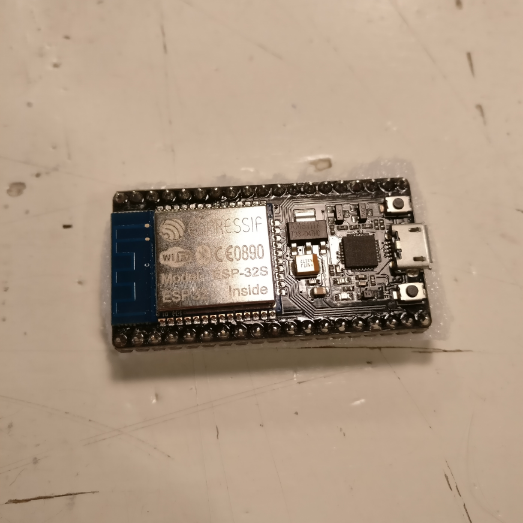
At the time I was developing this, the only ESP32 I could locally get within reasonable time was this nodeMCU devboard, which was quite expensive and too big for my project, so I decided to stick with the ESP8266 for now, but in a next version try to use the ESP32.
USB
The last consideration I had was that I wanted to have USB connectivity for both programming and serial interface, because I want my final project to be as easily accessible as possible for others. Because I don’t want to constrain users to just the functionalities I pre-program onto the board and to allow it to also be useful when it is not connected to the internet, a USB interface was an absolute must-have for this project.
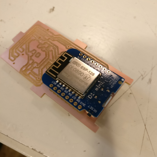
I found a board that has both the ESP8266 and a USB chip on board, which is the WeMos D1 mini, it is essentially a breakout for the ESP with USB, but what I like most about it is its small footprint, as it is a double sided PCB, with the ESP on one side and the USB chip on the other making excellent use of space.

PCB DESIGN PART 1
In the Input Devices week I already made a first version of the bricks, which at that point where not yet stackable and had very different sizes.
I started with the mistake of just working on the same Eagle layout that I had made for this previous model, not reflecting on what is wrong with it. So I went ahead and made three PCBs with the old dimensions, only realizing after milling three PCBs that the size is wrong.
And being an idiot, I already soldered the WeMos module onto the board that has the wrong size:
So I lost some time and stock because instead of working on all aspects of the project in a spiralized way, I was only focussing on the PCBs and thus not noticing they wouldn’t fit the LEGO dimensions properly.
BACK TO THE DRAWING BOARD
I decided to not build upon previously made designs anymore and re-design from scratch. First I wanted to get a deeper understanding of LEGO dimensions and systems, so I used these two images for the design.


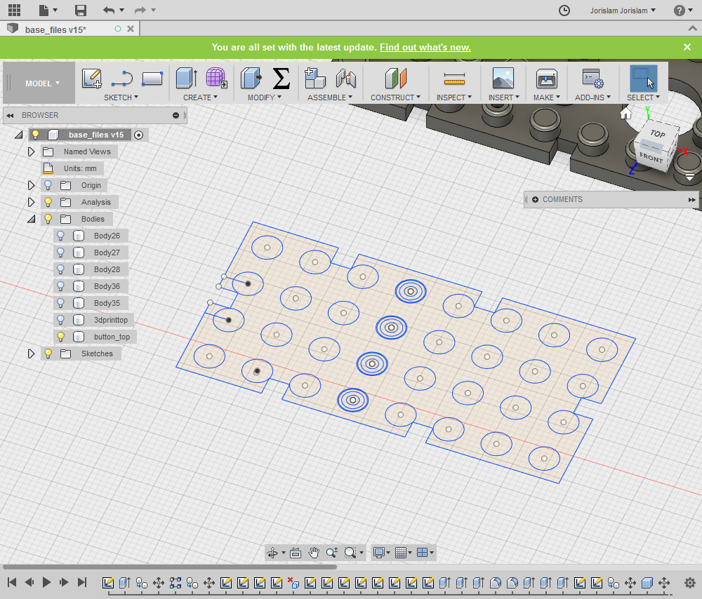
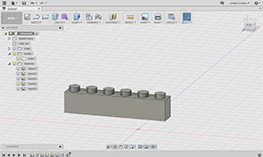
I designed a brick in Fusion360 that would just fit the biggest component being the WeMos, but still be acceptable for smaller components.

I also designed a PCB outline in Fusion360 that would fit the casing, which is the drawing on the right.
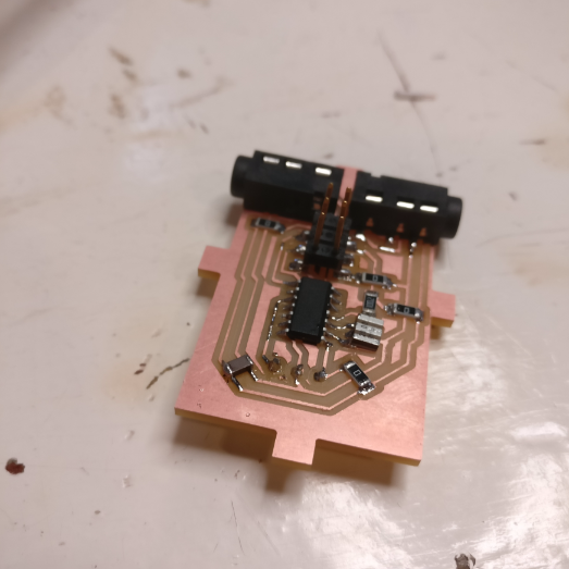
The first PCB I made was the one for the WeMos, as that is the biggest component and the tightest fit on within the standard brick dimensions. I downloaded the Eagle outline for the WeMos board href="https://github.com/SuperHouse/D1MSHO">here.
Then I designed a layout with the following constraints:
- The USB port should be at the very end of the board for easy access
- There have to be four holes for vias to the other side of the board as connectors for a stacked brick
- There have to be two audio jack connectors
Also on this board are a ws2812b LED with integrated driver, some generic capacitors and resistors, and a pad that can hold an additional button in the future.

I milled this first board, and used it to try various things, for example, the way another brick can connect to the bottom, the way it can connect to pogo pins on top and if it would fit the casing.
I laser cut the casing which at this point doesn’t yet have the 3D printed top with pogo pins, just to see how everything would fit, you see it here compared to the previous, much bigger casing.

COMPLETING THE FIRST SPIRAL
When I knew this first board would fit my desired size, it was time to work on other aspects of the brick in order to complete the first spiral of development and making a complete brick.
making connector pads
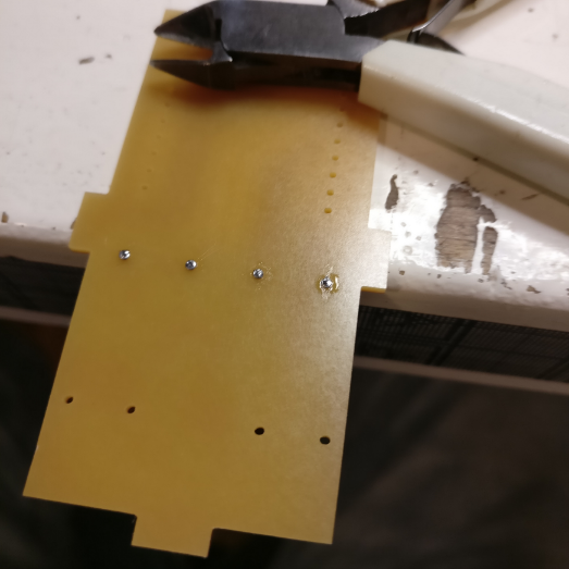
The next thing I did was work on the way the bricks would interconnect when stacked together, so the first thing I had to figure out was a connecting pad on the other side of the PCB.
First I used these small rivets to make a via and a pad on the other side:

Even though this is is a very sturdy way of doing it, I was afraid the size of the pads wasn’t big enough for a solid connection to the pogo pin touching it, so I had to look for a way to create a bigger pad. I could have done this by making a double sided PCB, but I felt it would be wasteful to use a double sided PCB just for these four small pads, so instead I used copper film that I cut on the vinyl cutter into little circles with a hole in the middle.


I attached these to the bottom of the PCB in the place where the pogo pin will touch.

So now I had a PCB that could be connected to from the bottom, I now needed to figure out how to make the ‘male’ side of the brick to connect to a brick on top of it.
In previous weeks I had already played around with pogo pins, and I really liked the idea of them because they can provide a connection to the next brick with good tolerances as they can be pushed inwards, and if you for instance would place a regular LEGO brick on them, they will also just be pushed inwards and not be in the way.
picking a pogo pin
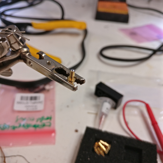
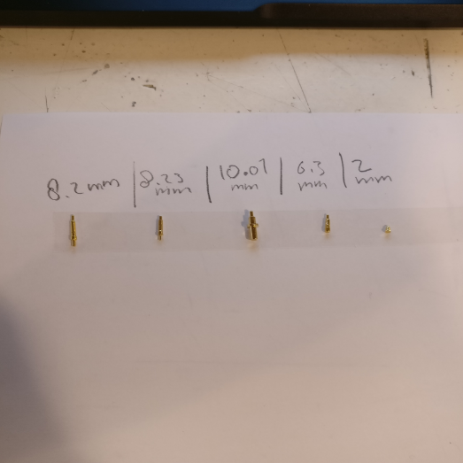
I ordered a bunch of different pogo pins to review various shapes and sizes to see what would work best for my application. To do this, I 3D printed a simple LEGO studded part with a small hole so I could see how it would fit.

These are the different parts I reviewed.
I used a simple 3D printed part with a hole to see how the pogo pin holds up against the dimensions of the studs.

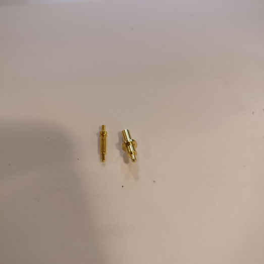
Eventually these two remained as the best options:

Eventually I chose this one, a pogo pin from MillMax:

I sourced it from Farnell, and you can find it here.
3D PRINTING
Getting the 3D printed top part right was very challenging and took a lot of trial and error on different machines to get right. The requirements for this part where:
Studs should have great fit with original LEGO bricks
Studs should have great fit with laser cut bottom part of other bricks
Print quality should be able to withstand repeated contact and friction
Top should be perfect fit with pogo pin, letting the top through, but stopping the entire pin to go through.
3D design in Fusion360
Making the 3D design in Fusion360 is very straightforward, I simply took the sketch for the bottom part and instead of leaving holes, extruded them higher to form the studs.

One thing that requires some more meticulous design, trial and error are the holes in the studs that fit the pogo pins. To make these, I measured the pogo pin with calipers and used dimensions from the datasheet. Because 3D printers always add a little bit more material than you think you just need to make a print and try it to see if it fits. As a general rule of thumb I made every pocket about 0.5mm wider than it should be to get a good fit with the pogo pin.


a chronological order of problems and solutions
To make the laser cut acrylic snap fit with the 3D printed part, there are small parts between the studs where the acrylic can snap in the top part. However, I placed these next to the holes for the pogo pins, which resulted in the printer making this one big hole.

To solve this I moved the space for the acrylic to other parts of the top where there are no holes for pogo pins, and a quick test print showed this worked well:

The next problem: on the BCN 3D printer we have at the lab, it would make a big mess between the studs, even on the highest possible settings:

This meant that there would never be a good fit with other bricks.
Later I figured out that increasing the retraction settings in the advanced menu of Cura helped a lot, but before I figured that out I sought refuge with an Ultimaker.

To prevent the print from warping, which is always does on an Ultimaker with flat surfaces, I used blue tape which gave a good bed adhesion.

The problem with this however was that the tape fused with the print and was very hard to remove completely.


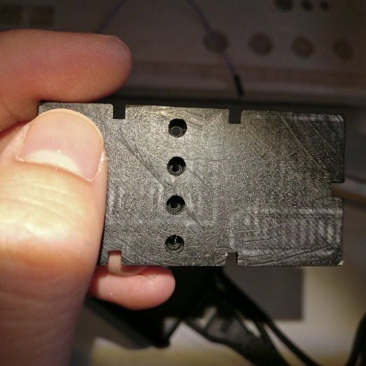
Another problem both with the BCN and the Ultimaker is that they both made a big mess inside the holes for the pogo pins, which means a lot of post processing to make the pogo pins fit nicely. You can see in this picture the holes are almost completely full with filament strings and not uniform at all:

the solution: Sindoh
My friends at 3Dprinting.com own a Sindoh 3Dwox dp200 printer, that has a textured bed, which means no need for blue tape and no warping.

I made some parts on it, and the result was amazing:

The inside of the holes came out completely clean!

The fit with the laser cut piece was also very good.
bonus: ABS
In our lab we are not allowed to print ABS due to health concerns, but my friends who own the Sindoh have it in a dedicated workshop to allow ABS printing, which the Sindoh is also really good at. Besides the fun-fact that original LEGO pieces are also made of ABS, this material glues, or rather welds, perfectly with acrylic. Using an acetone based glue you can fuse the 3D print and the acrylic together to form an extremely strong bond.
LASER CUT CASING
The design of the casing is pretty straightforward and only included three pieces, two of which need to be made twice for each side. I made this the basis for the design, and for different bricks I made slight variations, but always the same dimensions.

In the computer controlled cutting week I already did a lot of research into kerf and how to make parametric LEGO designs in Fusion360, you can find that research here.
Building upon that week’s experience, I only made a few more tests to get a good snap fit on the new design:

The biggest problem to solve with the laser cutting was not the kerf, but it was the fact that I would get really bad warping of the bottom part that has all the holes.
It might be a little hard to see in the picture, but when you lay a brick flat, the corners come up and the brick isn’t flat.

The cause of this problem lies within the corner power settings of the laser cutter. A circle is essentially one big corner to the laser and thus performed at a low speed. Because of the low speed and all the circles being close to each other, the piece endures a lot of heat causing it to warp.
To solve this, I did two things, first I found the lowest possible corner power for my design, which in my case was 15%, and second I made the laser as inefficient as possible by creating different colors and spreading them out as much as I could.


I also made it do other parts in between to allow the bottom plate to cool down before doing another set of holes.
FIRST ASSEMBLY
So I now have:
Laser cut acrylic
PCB
Pogo pins
3D printed top part
To put everything together I had to find a workflow, as the 3D printed top becomes attached to the PCB via the pogo pins and jumper wires. I will show you the example of the brick I made with the transparent/white top for the LEDs:
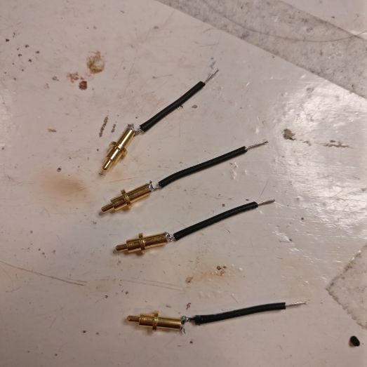
First, put some solder on the bottom of the pogo pin:
Next, solder jumper wires onto the pogo pins:
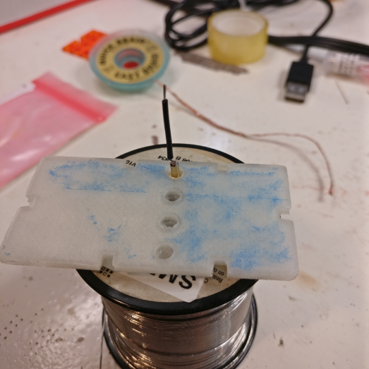
Put the pogo pins in the holes of the 3D printed part and hot glue them in place:

Stick the ends of the jumpers through the holes in the board and the holes in the copper pads and solder them together.
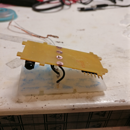

This is the first finished brick:

MAKING MORE BRICKS
After making the first brick with the right size and dimensions, I was ready to make other bricks to see if the system of stacking and connecting would work. I decided to start with the toughest one, the LED output brick. For this brick I wanted to:
Fit as many ws2812b LEDs as possible
Drive them over I2C
Make a frosted casing to diffuse the light
First I made the PCB and later I would adjust the casing if needed to this PCB.
MAJOR PROBLEM
So before I continue I have to tell you about a major problem I ran into, I don’t know how I did it, but something went wrong when saving the files after I had made the board and I lost the layout for the LED brick. I have the schematic and the exported PNG I used to mill it, but the Eagle layout file is lost and therefor I also won’t be able to share it on this page.
That being said, I will show you how I made the brick:
First of all the schematic, I used an ATmega328 to drive the LEDs and translate the I2C signal into a signal the LEDs can read.
To make this board, I used experience I gained during the output devices week, where I already made a PCB and brick with integrated ws2812b LEDs. You can find the documentation about these LEDs and how to use them here.
This is the new schematic I made for this board:
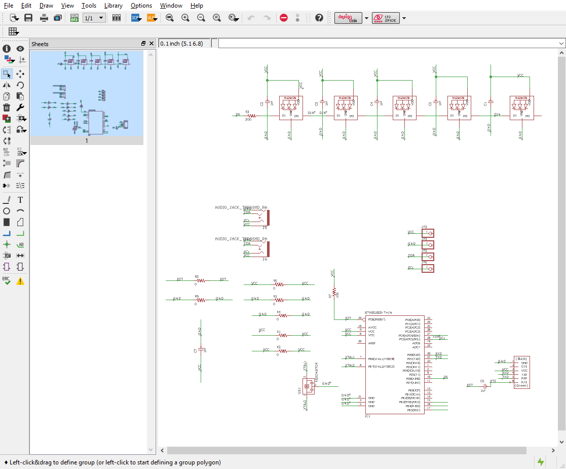
Because I don’t have the layout file anymore, please see this PNG for an idea of how I made the layout:
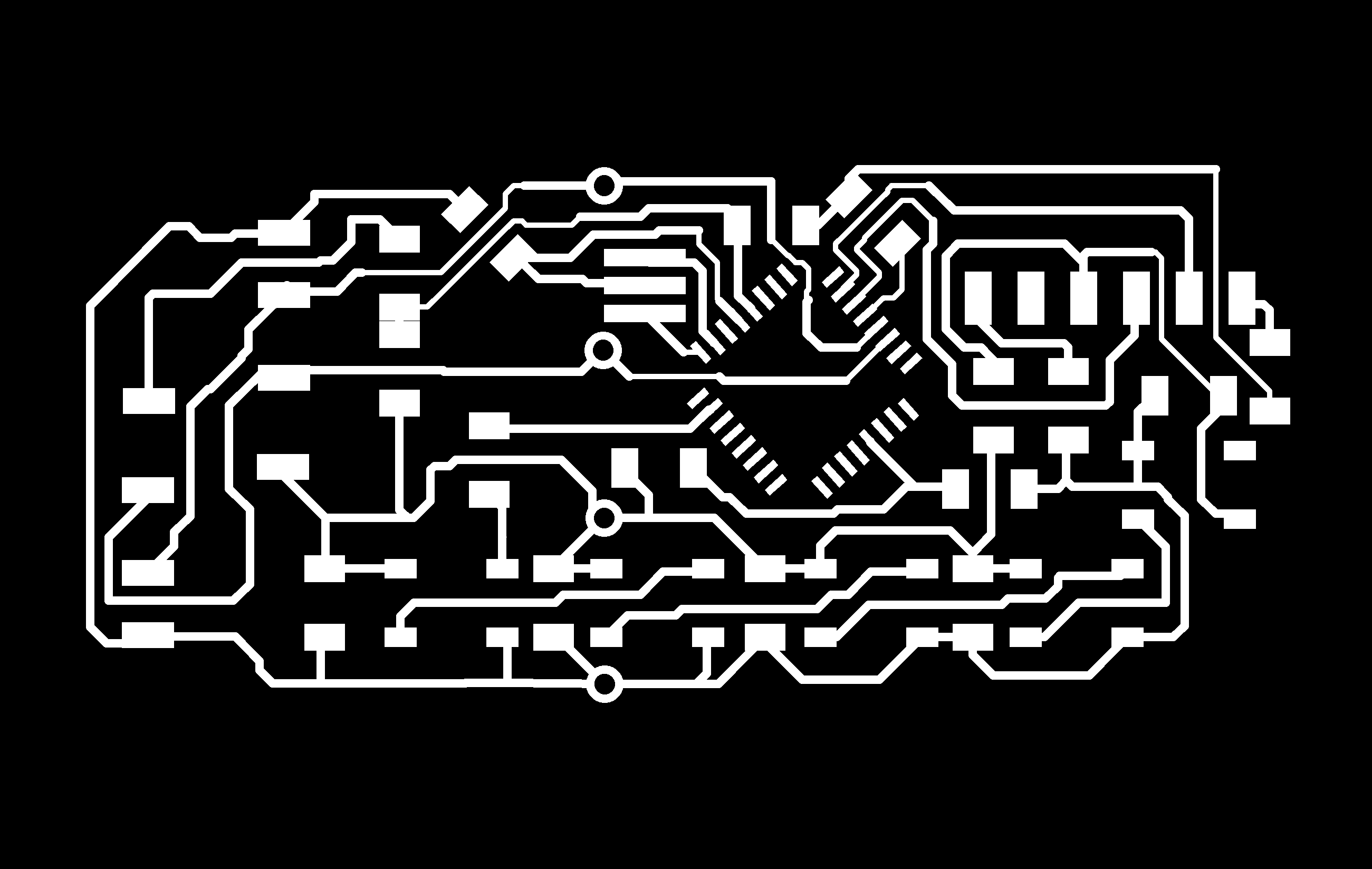
Because I wanted to optimize space on the board I decided to not include the six pin header to burn the bootloader on the microcontroller. More on that later.
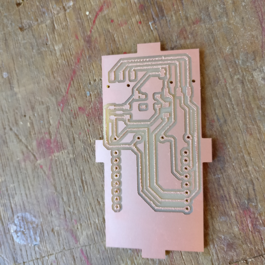
This is how the first board looked after milling:

It all looked fine, but when I soldered the FTDI header on lastly I noticed I had a weirdly placed a capacitor in the top right corner that did not sit well with the FTDI header.

So I took all the components off the board, gave the capacitor a different position and remade the board:(the audio jacks were added later)
BOOTLOADER & TESTING BOARD
Because I want to save space I didn’t include a six pin header to program the ATmega on my LED board and we didn’t have pre-loaded ATmegas from our supplier, so I had to burn the bootloader on a different board.
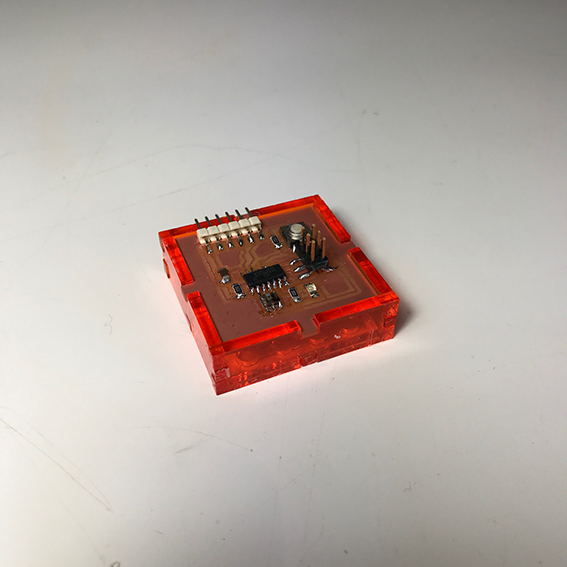
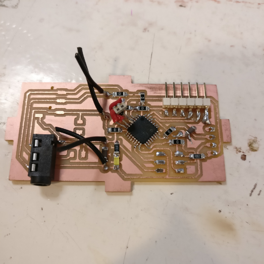
That is why I designed a programming and debugging board that has no other function than to be as simple as possible which can:
-Burn bootloaders
-Upload sketches via FTDI
-Communicate over I2C
So I made a simple board for the ATmega328 on which I can solder and rework an ATmega to program or test it:
First, you solder the ATmega on:

Then you burn the bootloader using the Fab ISP:

Then you test it by uploading any demo sketch using FTDI:

If everything works you take the ATmega off using a heat gun:

back to the LED PCB
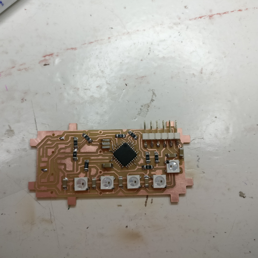
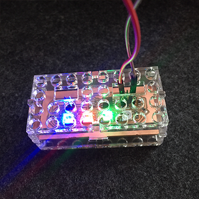
Once back on the LED brick, I programmed a Neopixel library demo sketch and uploaded it to the PCB to check its correct operation.

I laser cut the casing out of frosted acrylic and combined it with a 3D printed top I made using transparent filament:

I didn’t glue it together yet as I might still need to debug and access the PCB.
I2C COMMUNICATION
Because I want to make all the bricks talk to each other over I2C, I needed to do some software and hardware testing.
First of all, as I2C requires a 4K7 pull-up on both the data and the clock line, I needed to figure out if the WeMos board does this internally, or if I should add these to the WeMos breakout board that I made.
To test this, I made an I2C connector on my test board with pads for 4K7 resistors, but I didn’t solder them yet. Instead I just connected the WeMos to the test board and made them communicate over I2C using simple example code.

The code I used to test this is the example code in the Wire library in Arduino IDE is the slave_sender and master_reader.


I used these examples to send data from the ATmega to the WeMos, which worked perfectly, so I knew there was no need for adding the 4K7 pull-up resistors as the WeMos probably uses internal pull-ups.
SENSOR BRICK
The next brick I made is a sensor brick that holds a BME280 temperature and humidity sensor on an I2C breakout. Because the sensor in this configuration already sends an I2C signal I had very little to design on the board of the brick. Except for making it fit the brick and putting on the audio jacks, bottom pads and pogo pins I just added a status LED and resistor to show when it is connected.
These are the schematic and layout:


The first version of the board didn’t have the status LED in the design yet, so I just soldered that on later, but the file you can download does have it.
Assembled it looks like this:

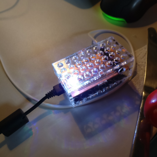
PROGRAMMING
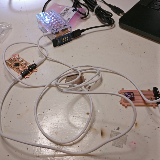
Before glueing everything together I wanted to make sure the code worked, so I had this setup in which I connected the LED PCB and the temperature sensor PCB to the old brick which has a WeMos inside using audio cables.
code outline
The goal for the code is to create a way for the bricks to all communicate over I2C and to send the data via WiFi to a server where it can be visualized and manipulated.
For the server side of things I decided to go with a free service called AllThingsTalk which is a web based application you can find at maker.allthingstalk.com.
I signed up for an account and downloaded their Arduino library which you can find here, you will also find other documentation on this page.
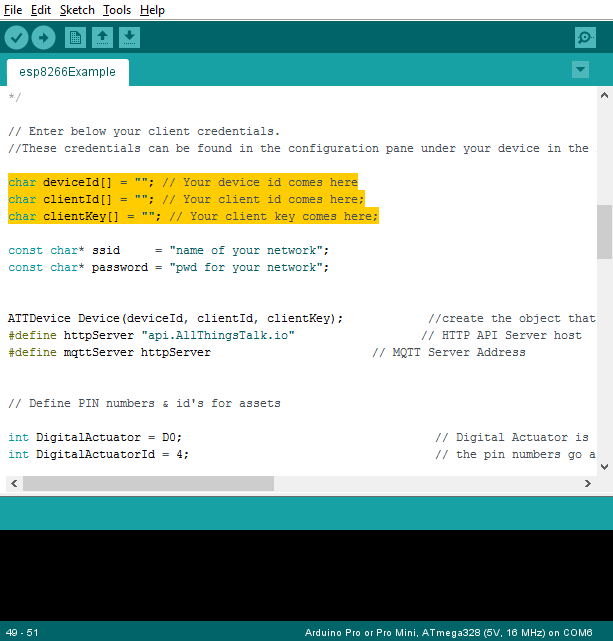
In the examples you fill find the esp8266Example, which is an example sketch for the ESP8266, which is the WiFi chip that is on the WeMos which is in the main brick.
You will need some IDs and keys to set up your Arduino code, to get this, follow these steps on maker.allthingstalk.com:
setting up AllThingsTalk
-First, make an account and sign in.
-Click on ‘New Ground’

-Name your ground

-Click ‘connect a device’

-Click ‘Your own’

-Give it a name

-Go to settings so you can see your unique IDs

You’re now set up on AllThingsTalk, you need the credentials you see in your settings and put them in the example sketch that is in the library:
Arduino Sketch
Here is what I programmed the bricks to do:
-main brick should connect to internet over WiFi and show if it is connected
-main brick should collect sensor data and send it to AllThingsTalk
-LED brick should visualize the amount of humidity in real time
The code that I wrote consists of two different elements, first of all there is the code on the main brick, running on the WeMos that needs to receive I2C data from the temperature and humidity brick and it needs to send I2C data to the LED brick. In addition it has to send the data from the temperature and humidity sensor to AllThingsTalk via WiFi.
Then there is also the code that runs on the individual bricks to either send or receive I2C data, the sensor brick doesn’t need software as the sensor sends I2C data by default, but the LED brick does need its own code to interpret the I2C communication and translate it to commands the drivers in the LEDs can understand.
First of all, these are the libraries you need to install that my code calls:
AllThingsTalk Arduino library
Adafruit Neopixel library
Adafruit BME280 library
Let’s start with the main code on the WeMos:
-First, I made four tabs, which are basically four sketches in the same folder, to keep things organized:

-Then I’m declaring all the libraries I’m going to use:

-Here is some info for the one ws2812b LED that is on the main brick board as status indicator, here it is declared that there is 1 pixel and the data pin is D4.
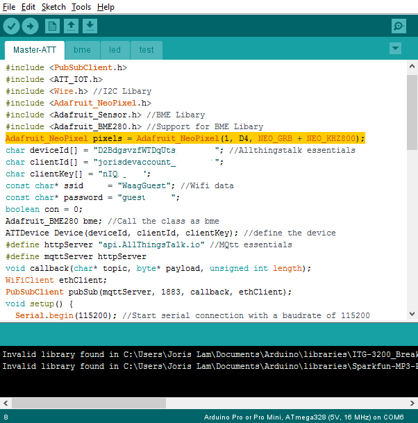
-This is the ID for AllThingsTalk that I showed you above how to acquire:

-Here you enter the SSID and password of the network you want to connect the brick to:

-This is all stuff from AllThingsTalk, don’t change it:

-In the void setup, the serial connection is started, the WiFi is started and the ws2812b LED is started:

-This part addresses the on board LED to show if it is connected to the internet via WiFi, if it’s connecting it will blink white, if it is connected it will be steady white and when it is not connected it will be red.

-You don’t see the typical way of addressing a Neopixel here, that is because there is another sketch in the same folder open as a tab called ‘led’. This sketch mainly addresses the LED brick, but at the bottom is the void setled that addresses the one onboard LED on the main brick:

-Back to the Master-ATT sketch, this is where the BME280 sensor is started:

-The ‘ledtest’ calls a little test where the LEDs of the LED brick all light up one by one to ensure proper operation, which you will find in the led sketch


-In the loop, the sketch calls the temperature and humidity as a float, this can happen because in the BME sketch the original BME280 library commands of getting data from the sensor are being converted to floats.
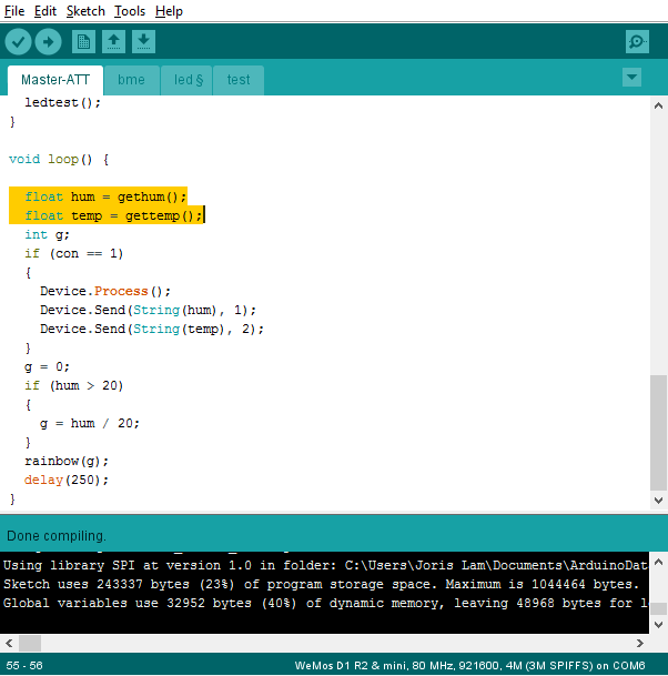

-This is where the temperature and humidity data are being sent to AllThingsTalk:

-The last part of the code makes the LED brick light up in rainbow colors according to how much humidity the sensor brick measures. The actual code for the LEDs is in the LED sketch.

-This is how the main brick communicates with the LED brick over I2C:

-To give each LED a different color, I used a so called ‘switch case’:

So now you have seen all the code that runs on the main brick, the WeMos, but in order to receive and translate the I2C commands, the LED brick running an ATmega328 also needs code, which is a different sketch called LED-slave.
-First it calls the Adafruit Neopixel library and the Arduino wire library:

-Then the integers which are also defined in the main sketch are defined here:

-Here you declare the standard Neopixel stuff which is the amount of pixels and to which pin the first one is connected:

-The I2C connection is started and the LED brick uses address 12:

-The pixels are started and flash white once to indicate the brick is working correctly:

-In the loop, the wire data is read for each parameter that is needed to tell the pixels what to do, and put in the correct format that the Neopixel library needs to drive the pixels.

FINAL ASSEMBLY
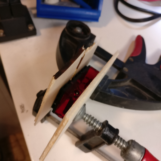
After the code was working I put everything together. I used an acetone based glue called ‘Acryfix’ to glue the bricks together and I used a needle and syringe to apply the glue very precisely.

I used clamps with small pieces of wood to apply pressure.
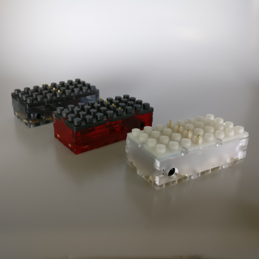
HERO SHOTS
The first three bricks when completed looked like this:

WIP
I also made two button bricks right before the final presentation, but I haven’t written code for them yet, so it’s a work-in-progress. These button bricks also hold an ATmega328 to handle I2C communication and will simply say if they are being pressed or not. They will be very useful in combination with AllThingsTalk because you can set rules to trigger when they are pressed.


IMPROVEMENTS & CONCLUSION
In conclusion I’m very satisfied with the potential of this project. These bricks can be used in many different ways and for many different purposes which I will evaluate in the weeks to come. Some considerations for the next iteration are:
-Be more flexible in sizes and make a design in which both small bricks and larger bricks can communicate with each other.
-Be more energy efficient for IoT use
-Use cheaper microcontrollers for I2C handling or use an ADC.
-Expand with a wider range of bricks.
BILL OF MATERIALS
I will break down the cost of each individual brick and afterwards add up all costs to a grand total.
main brick
1 x WeMos D1 Mini $4,-
1 x PCB copper clad approx $1,-
1 x ws2812b LED $0.06
1 x various resistors $0.50
2 x audio jack $1.9
4 x pogo pin $4,-
1 x acrylic $2.5
1 x ABS filament approx. $1,-
total main brick $14.96
BME280 brick
1 x BME280 breakout $4,-
1 x PCB copper clad approx $1,-
1 x white LED $0.06
1 x various resistors $0.50
2 x audio jack $1.9
4 x pogo pin $4,-
1 x acrylic $2.5
1 x ABS filament approx. $1,-
total BME280 brick $14.96
LED brick
1 x ATmega328 $3
1 x PCB copper clad approx $1,-
6 x ws2812b LED $0.36
1 x various resistors $0.50
2 x audio jack $1.9
4 x pogo pin $4,-
1 x acrylic $2.5
1 x ABS filament approx. $1,-
total main brick $14.26
GRAND TOTAL $44.18
APPLICATIONS AND IMPLICATIONS
In week 16, I answered the questions of applications and implications of my final project, but this was done before I actually finished the project. That is why I will answer them again with the knowledge I have now after finishing the project.
Please find my previous answers in the documentation of week 17 here.
what will it do?
The bricks I made are the foundation for an expandable, modular system of connected IoT devices which allow for easy hardware development.
The current bricks I made allow you to make a temperature and humidity sensor kit which sends data to a server over WiFi and the LED module allows you to visualize humidity data on the device itself.
I have integrated the code to work with a 3rd-party platform called AllThingsTalk which lets you see the data of the sensor brick in real time and store the data.
who's done what beforehand?
The bricks have LEGO dimensions and use the LEGO system to interconnect, so the industrial design of the stackable form factor has been developed by LEGO.
There are other somewhat integrated rapid development kits for IoT and hardware, but they all differ in form factor. You could compare this to a combination of Seeedstudio's Grove system, Littlebits and LEGO.
what materials and components will be required?
See bill of material above which lists all components and materials used.
how much will it cost?
See bill of materials above.
what parts and systems will be made?
See full documentation on final project page, but in short: a brick which connects to the internet, an input brick with a sensor and an output brick with LEDs all of which connect to an online data platform.
what processes will be used?
Electronics design and production, 3D design, 3D printing, laser cutting, programming in Arduino language, general parts assembly.
what tasks need to be completed?
I had to design a stackable system, make sure the bricks interconnect while stacked, design a standard size for the PCBs and casing and program everything.
what questions need to be answered?
I needed to find a suitable wireless technology to connect to the internet, find the right chip for WiFi communication, find the right communication protocol for the bricks to communicate, find a way to connect the bricks electronically when stacked.
how will it be evaluated
The evaluation on a technical level consists of simply checking to see if the bricks work as I have intended and to feel if they are well designed and constructed and can be connected and disconnected frequently without problems.
I found that the bricks turned out exactly as I intended, but I do see a lot of room for improvement in a next iteration. Both in terms of system, tolerances and build quality. I'm not entirely happy with the tolerances and the way they are glued.
Another point for evaluation is how easy others find them to work with. To test this I am hosting a series of workshops and hackathons with them over the summer with various groups of people, young to old to see how they react to it.
Based on user feedback I will make improvements for the next version.
DISSEMINATION
I intend to turn my final project into an open-source education and prototyping tool which can be used to learn about sensor technology, IoT and electronics.
To support this goal I am pleased to have been selected by the city of Amsterdam for a grant and programme to use these bricks to teach disatvantaged residents of our city about technology and electronics. I will host a series of workshops designed to teach people about
technology and to help them build their own sensor kit.
In addition I will also create a fully documented open-source manual on Wevolver.com where people interested in the project can not only learn how to make their own version, but hopefully contribute to the project by making improvements.
I will do the same for the software by creating a public GIThub repo where people can download and contribute code for the project.
During Fab13 in Santiago I will give a workshop and demonstration for those interested.

FILES
all code for main brick and LED brick (ZIP file)

all Eagle files (ZIP file)

3D print file

LED brick DXF

main brick DXF
BME280 brick DXF
ARCHIVE
These are previous updates and original ideas from the first week:
PROGRESS
I have tried to use most of the weekly assignments for my final project, and have already built quite a few prototypes and early versions. Below are some pictures of experiments made during the weekly assignments.
These were the first laser cut bricks I made, that didn't hold any electronics, but were just there to prove you could make LEGO compatible bricks in the Fab Lab.
The first PCB integrated in a LEGO compatible case
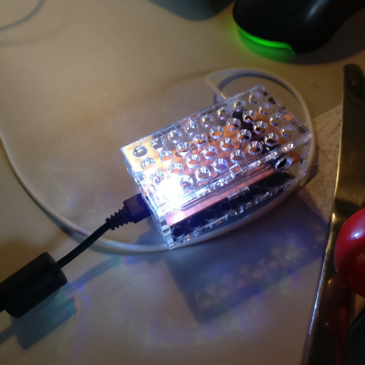
This brick has LEDs inside which I made during the output devices week.
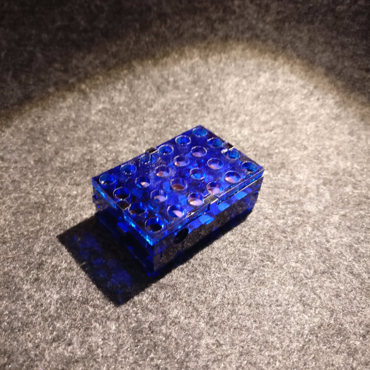
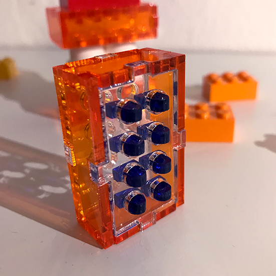
These were the first real prototypes of the prototype which hold a WiFi chip and the blue brick holds a temperature sensor
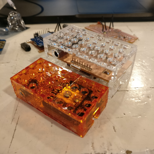
In week 17 I managed to make the WiFi brick(orange) considerably smaller compared to the clear one I made earlier, even though it holds the same components!
In order to make the bricks connect to each other when you stack them, the new PCBs have rivets on the bottom which will touch on pogo pins from the top of the connecting brick
I'm reviewing various sizes and types of pogo pins.
The new PCBs look something like this, the black wires connect from the PCB to the pogo pins that will be in the top layer.
THIS IS THE FIRST INFO I WROTE DURING THE FIRST WEEK, IT'S MOSTLY BEEN MADE OBSOLETE BY NEW DEVELOPMENTS BUT JUST AS A PIECE OF HISTORY THIS IS WHAT I THOUGHT ABOUT THE FINAL PROJECT IN THE FIRST WEEK:
My final project idea is to design a series of modular casings for protoboards, sensors, actuators and other modules that will connect to eachother using the basic principles of LEGO bricks. Because the utility patent for most LEGO brick expired around 2011, anyone is free to make building blocks that work with their system.
The reason I want to design this modular family is to allow everyone to prototype quicker and better, by being able to add quick, custom casing around their own projects. This for instance allows you to put your sensorkit outside straightaway, protected from the rain, and because it's LEGO based, if you need it to be a few centimeters bigger, just add a few LEGO bricks that you steal from your nephew! This modular system will hopefully accelerate turnaround time for prototypes of all kinds, but could also be great for more playful applications, like making your Star Wars LEGO interactive, that way parents can introduce children to STEM in a playful way, or just build an Arduino powered X-Wing fighter for themselves ofcourse.
In order to make a succesful final project I plan to work as following:
1 - formulate concept and mission
2 - come up with an integrated project concept that showcases the full possibilities while also conforming to the Fab Academy requirements of a final project like having an input brick, microcontroller brick and output brick
3 - make a list of requirements for the basic modules, for example make sure it fits a half size breadboard and Arduino uno, etc.
4 - design a custom Arduino based PCB that fits the LEGO system
5 - design parametric script to make customizing and resizing easier
6 - design a 'community interface' and think about how the world can take the concept and modules to make their own version
To better understand the anatomy of a LEGO brick I bought some and started to try to model them in 3D to get a better understanding of how they are designed.
Here I will continue to write down some ideas as they come and go in the coming months:
-output: make a transparent neopixel brick so I can make status indicator lights or a brick screen easily
-input: create easy physical interaction between much used sensors and the brick system
-microcontroller: mill a PCB in a shape that fits the bricks and that makes it easy to add 'brains' to any LEGO project
UPDATE
I made a quick 3D print based on a previous case design I made to include some LEGO compatible edges, and yay! It fits!
 Another thing I experimented with is putting a neopixel style LED in a transparent brick, which also seems to work after drilling out a piece of the brick.