10 - output devices
This week’s assignment was to make a board and use it to control an output device.
First we got a lecture from our local instructor Emma Pareschi on the use of different output devices like:
-Motors
-LEDs
-Speakers
I chose to use RGB LEDs with a built-in driver to focus on this week, as I will also use them in my final project.
During the embedded programming week I already made a FabKit with a built in RGD LED with driver, but this didn’t work. So I started this week by debugging the FabKit before making a new board.
ABOUT THE LEDS
I wanted to work with individually addressable LEDs known to many as ‘Neopixels’. These LEDs have the property that you can chain a big amount of them and drive them over one single dataline. With a traditional RGB LED you would need three wires for each LED, which is fine if you’re using just one or two, but if you want to use 10 or 50 for example you will need too much wires and code to handle it all.
You often find these LEDs on strips or breakout boards, but the component itself looks like this:
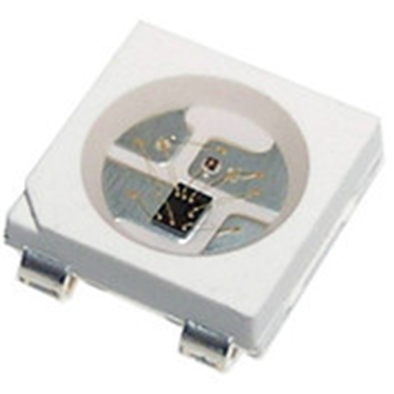
Under a microscope you can see the black square which is the IC that controls the different colors inside the LED:

The specific type I used is the ‘WS2812B’ from Semiworld, the datasheet can be found here.
https://cdn-shop.adafruit.com/datasheets/WS2812B.pdf
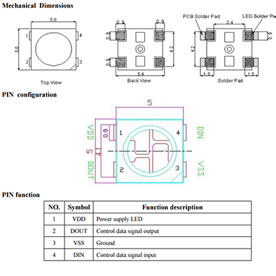
The most important information in the datasheet for my project is the way they should be connected:
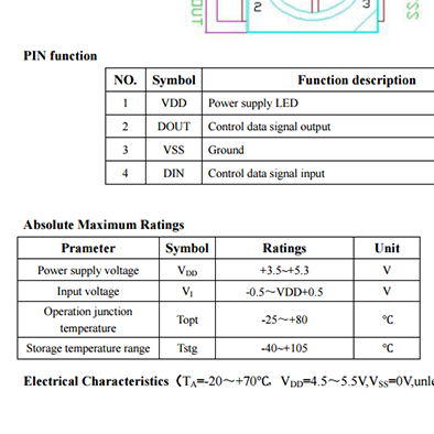
The supply voltage range:
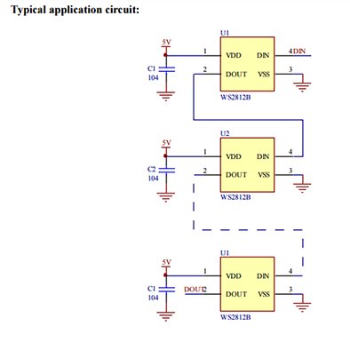
And the typical application circuit:
THE FABKIT
When I designed and built a FabKit during the embedded programming week I included a WS2812B LED in my board which didn’t work. This is the full layout of the board:

And this is how I connected the LED:
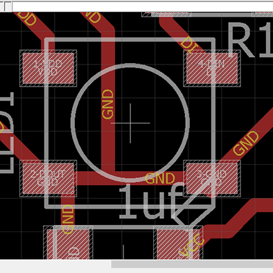
The data-in pin of the LED is connected to pin 6 on the microcontroller, as this is the standard pin that is in Adafruit library examples. The VCC pin is connected to VCC and GND is connected to ground.
I made two mistakes when in designed the board, one is that I didn’t add a dedicated capacitor for the LED, but that turned out not to be the real problem, the real issue was that I connected the data out pin of the LED to ground.
The data out pin on these LEDs should only be connected to another LED that is next in the chain, but if it is the last(or only) LED, it should simply not connect to anything.
The correct layout for this board should have been like this:

Because I didn’t want to completely re-do the board, ‘franken-hacked’ the board by doing the following:
First I took the LED off the board using a hot air gun, then I used a knife to cut all the traces around the data out pin. Because this also meant I cut the ground trace that the resonator connects to, I used a jumper wire to connect the resonator to an alternative ground trace. It’s not a pretty sight but it worked!
NEW LED BOARD
For my final project I want to build a set of IoT Lego bricks, some of which will be input bricks and others will be output bricks. That is why this week I started by making a first version of an output brick with LEDs.
Because I want to keep the system of bricks as cheap and small as possible I wanted to use the cheapest microcontroller for the job, after some research I found out that the ATtiny85 is the first model from Atmel that can drive these specific LEDs, so I designed a board around that one.
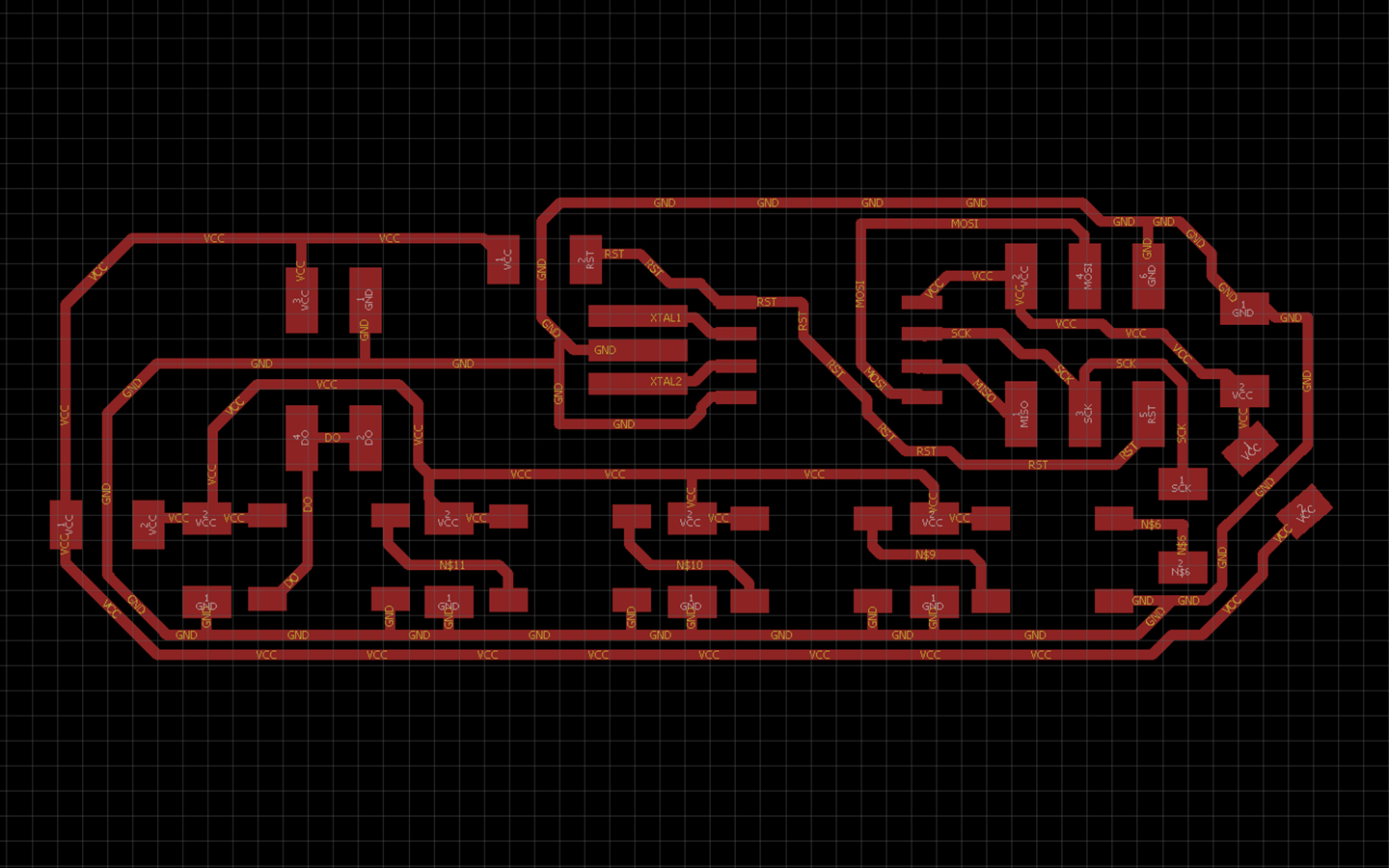
These are the schematics and layout of the board:
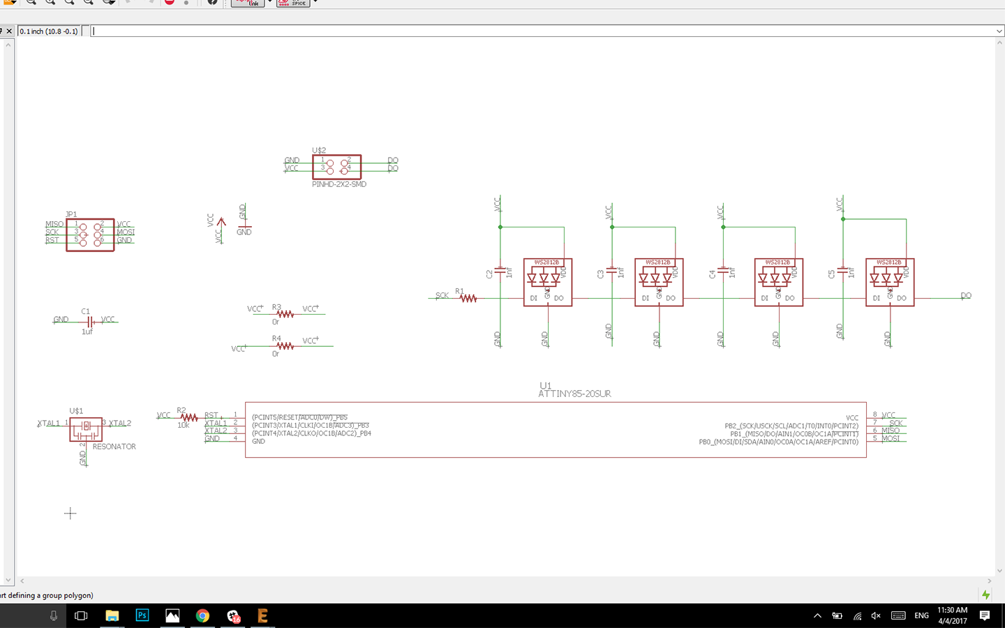

In the definitive version for my final project I want the bricks to be stackable on top of each other and use a USB port and integrated FTDI chip to program and power the main brick which will hold a ATmega328 or ESP8266. But for this first board I made to be programmed and powered through the programmer with a 2x6 header.
To extend the amount of LEDs you can add, I included a 2x4 header which connects to the data out of the last LED. It also has a connection to ground and VCC to add up to 20 LEDs more over the same power line, but more about that later.
For the symbol and footprint of the LED I used the Adafruit Eagle library which can be found here: https://github.com/adafruit/Adafruit-Eagle-Library
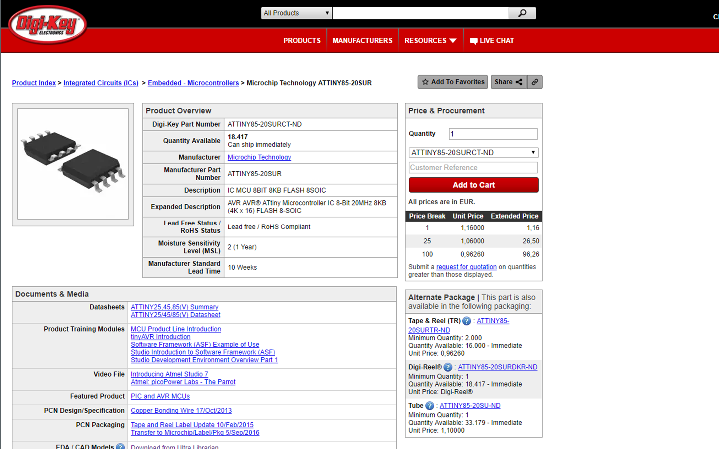
I found the ATtiny85 Eagle library files through Digi-Key, and you can download it here
https://www.digikey.nl/products/en?keywords=ATTINY85-20SURCT-ND
The main problem I ran into when making this board was that some of the LEDs didn’t seem to work. Because I was still waiting for an order of the LEDs I took a strip of LEDs that had them pre-soldered and removed them from the strip.

For the first two LEDs this worked well, but I couldn’t get the third and fourth LED to work and couldn’t figure out why. I completely debugged the board following these steps:
-check for shorts using multimeter
-remove and re-solder LEDs
-try different code
-connect to an external LED strip using jumper wire
After I concluded that the board was good I connected and external strip of LEDs to the first data pin of the board and saw that the code was good and the LED strip lit up as it was supposed to do. The problem turned out to be the old solder on the LEDs that I had removed from the strip. It didn’t fuse well with the new solder I used. I removed the LEDs and used
de-soldering braid to clean the PCB. When the order of new LEDs came in everything worked immediately as it should.
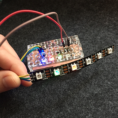
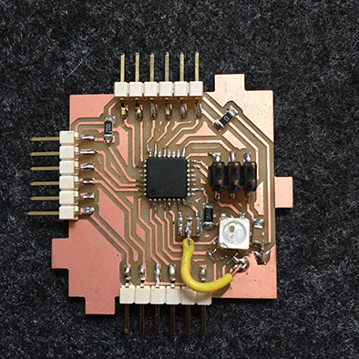
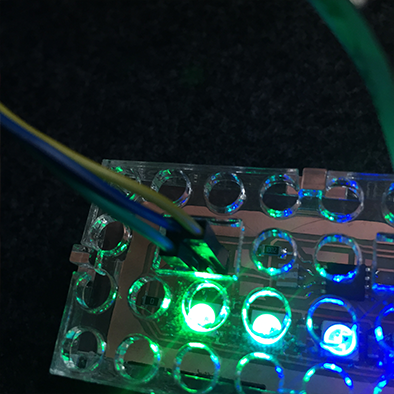
After I completed the board it looked like this:
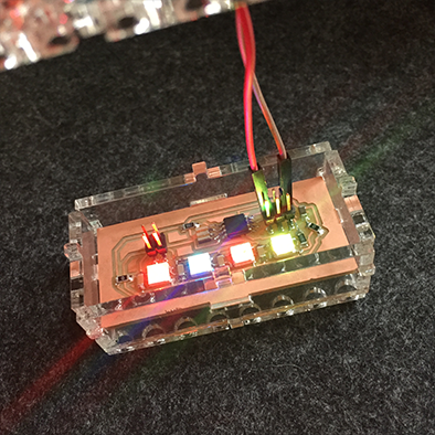
I laser cut a casing out of acrylic for it that makes it LEGO compatible.
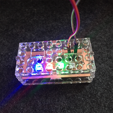

To connect a strip after the brick, you can use the connectors which give data, vcc and gnd.
POWER MANAGEMENT
The board is currently powered through the ISP and USB port of my computer. A typical USB 3.0 port gives about 900mA, and a single LED at maximum brightness showing all colors draws 60mA. However, if you set them all to white at the same time at maximum brightness you won’t reach this power consumption. If the board and ISP wouldn’t draw any current you could theoretically power at least 15 neopixels with a USB port. So the four LEDs on this board should be no problem, but I do advise that when you build this board and extend the strip beyond ten additional LEDs you should use an external power supply for the LEDs that come after the board. To do this you just connect the data in of the new strip to the data out pin dedicated on the board and connect the rest of the strip to external power.
PROGRAMMING
To program the board and LEDs I used the Arduino IDE and the Adafruit Neopixel library.
You can download the library here https://github.com/adafruit/Adafruit_NeoPixel
As I wasn’t really interested in programming them as much as I was in getting the hardware to work, I used one of the examples in the library called RGBstrandtest.
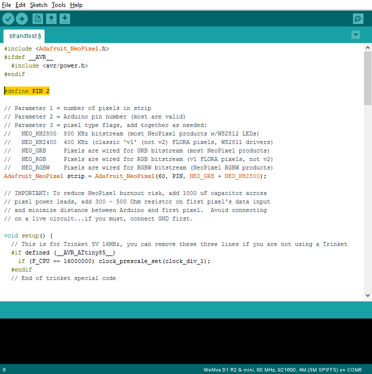
To work out which pin I needed to address in the code I used this image:

Because I connected the first data-in of the first LED to pin 7 on the microcontroller, this image showed me that I needed to write pin 2 in the code.
When programming Neopixels with the Adafruit library there are only two variables that you need to set correctly, the pin the first LED is connected to and the amount of LEDs in the chain. In my case this was pin 2, and I said I had five LEDs connected, even though there are only four on the board so I could test if the external strip would also work, the first LED of that one being LED five in the chain.
First you define the pin to which you connect the first pixel:
Then you change the first number in this line to represent the amount of LEDs you have connected:

From this point onwards the demo sketch just does its thing and the LEDs will light up in various ways, but if you want more control over your pixels, it is good to know how to program them.
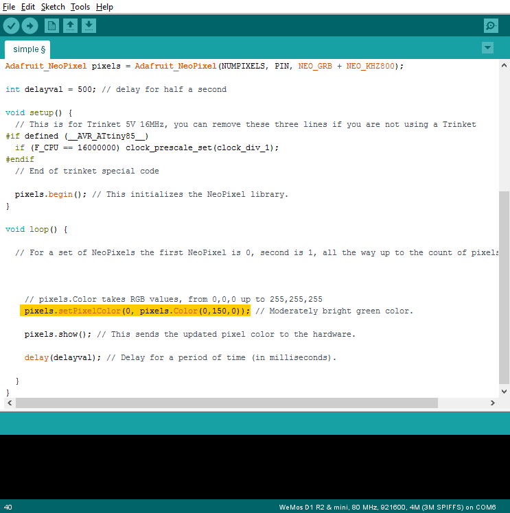
To get a better understanding of the basic working of this code, lets look at the 'simple' example from the Adafruit library:
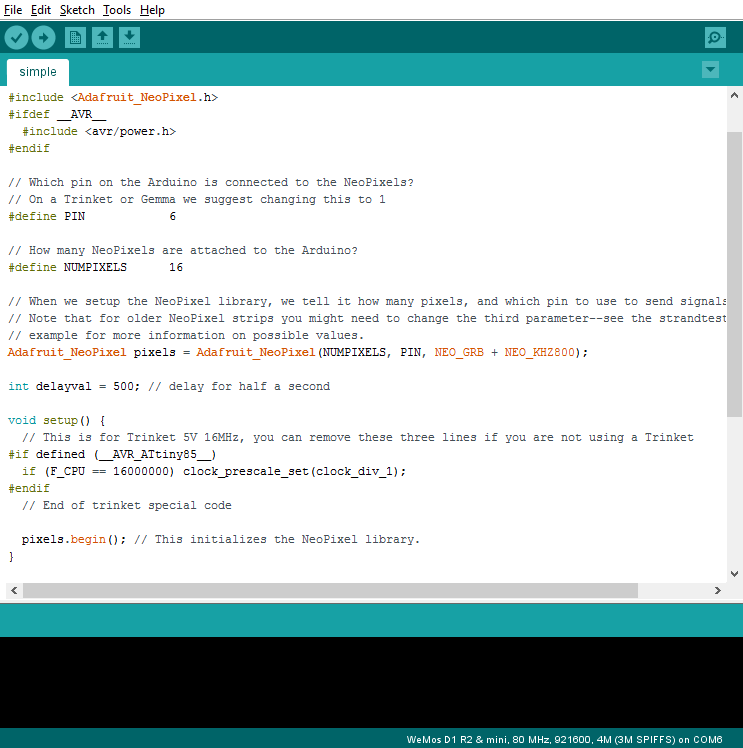
This code is pretty much the same but easier to break down, first of all, after setting the correct pin and amount of pixels, you will find this command in the void setup to activate the pixels:
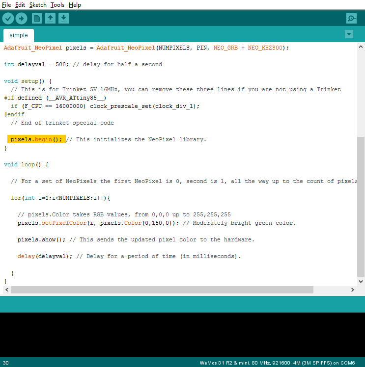
The most simple thing you can do is write this line which will give you individual control over an individual pixel, the first number(in this case 0) indicates which pixel to address. Note that the first pixel is not 1 but 0! The other three numbers indicate the R(ed) G(reen) B(lue) color values and can range from 0 to 255.
casing

Eagle schematic

Eagle layout