15 - networking and communications
15 - NETWORKING AND COMMUNICATIONS
My final project involves multiple forms of communications, the sensor bricks need to be connected to the internet over WiFi or narrowband IoT, but they also need to communicate amongst each other. I’m thinking of adding a Bluetooth chip, but the main communication between the bricks will run over I2C, so that’s what I focussed on this week.
So how can two devices/controllers/processors communicate with each other over a wired connection, and why would you choose I2C rather than SPI for example?
I found this explanation on Sparkfun very clear on explaining the basics:
https://learn.sparkfun.com/tutorials/i2c
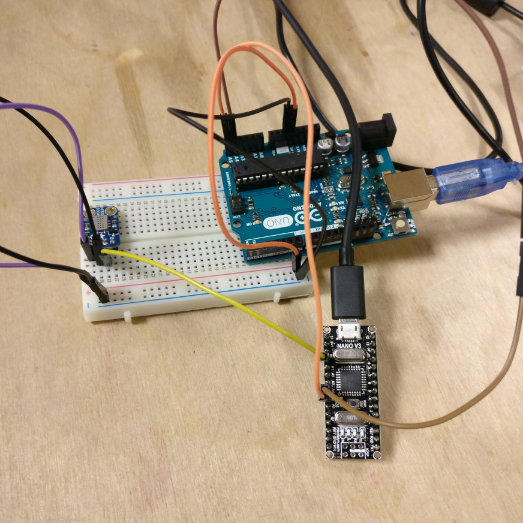
It basically comes down to this, if you want two devices to communicate, you could just use a transmit(TX) and receive(RX) line and be done with it.
There is nothing wrong with this setup, but it is strictly limited to two devices, so if you want to create a network with multiple nodes, this won’t work.
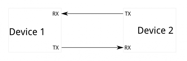
One alternative is the SPI protocol, which allows one master to have multiple slaves.
This protocol needs a dedicated line for each slave, which means you can have as many slaves as you can have lines/pins. This could work for a small network, but if you have more than let’s say 10 slaves things get complicated.
That is why the I2C protocol is a very good solution to this problem, the I2C protocol only needs two data lines and can be linked with hundreds of slaves to one master who all communicate over the same data lines.

The reason this works is because it sends data packages with an address before it, so only the slave with the right address will pick it up.
The only condition you need to take into account for I2C to work is a hardware requirement for the datalines. Both datalines need to have a pull-up resistor of 4K7 in order for the protocol to work. This is due to the fact that the master pulls down the clock line before sending a package to signal the slaves that data is coming.

THIS WEEK’S ASSIGNMENT
This week I wanted to see if I could get I2C to work on my ATtiny84 board to read an analog sensor value and send it to another controller over I2C.(spoiler alert, it didn’t work)
To understand the protocol, I started with a very easy setup and examples to build my first I2C communication. I used an Arduino UNO as a master and an Arduino Nano clone as a slave. Both have an ATmega328 microcontroller.
The code I used is standard example code from the Wire.h library found in the Arduino IDE. I used:
master_reader

And slave_sender

I uploaded both sketches to the boards, and I wired the the data lines to have a 4K7 pull up each, but nothing happened.
It wasn’t until I removed the resistors and wired the data pins from each board directly to each other that the communication started working:

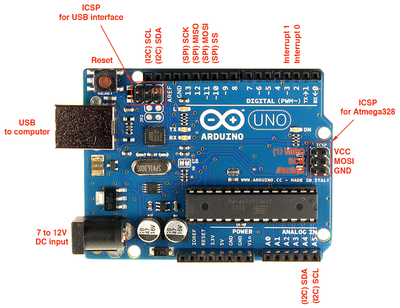
The pins on the Arduino Uno and Nano for I2C are A4(SDA) and A5(SCL).
My guess is that either one or both of the boards have resistors on the board that connect to the I2C lines for this very purpose, or that this library calls upon the internal pull-up resistors of the microcontroller. This highlights the problem with coding with Arduino IDE and not in C, a lot of what’s going on under the hood stays hidden.
When you look at the example code, there are two important ‘rules’ to abide by, which are what the master expects and what the slave sends. These things need to match otherwise they will not read each other’s data right.
First of all, the master is requesting a package from a slave with address 8, followed by a 6 bit message.
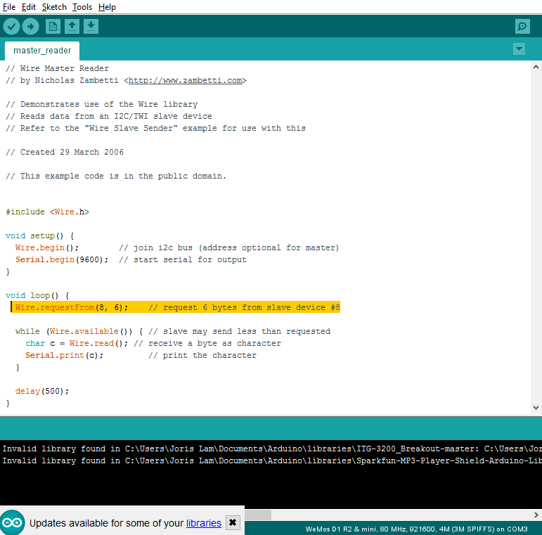
So we know that the slave needs to have address 8, and should send no more than 6 bits of data. In the slave code you can clearly see this here:

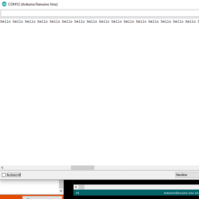
And as you can see in the serial monitor from the Arduino UNO, it receives the ‘hello’ message from the Nano over I2C.
USEFUL SOFTWARE
When debugging or when you buy an I2C device like a sensor or display that you didn’t program yourself you often don’t know the address of the device. Also, sometimes the data isn’t flowing but that doesn’t always mean the connection isn’t working. I found a very handy sketch online which is called I2C scanner. This sketch for a master simply listens for slaves and serial prints their address to the serial monitor.
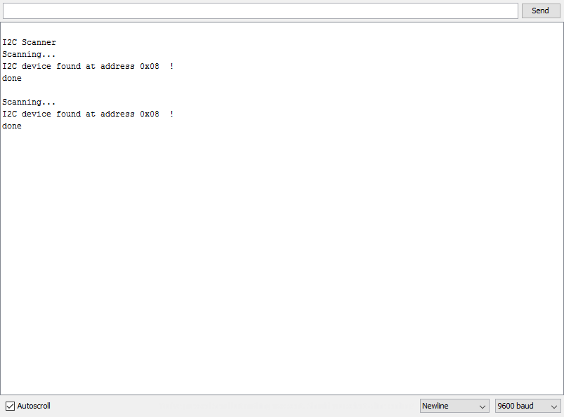
I didn’t write this sketch, but I included it at the bottom of this page, all the authors are listed in the sketch.
ANALOG SENSOR VALUE OVER I2C
During the input devices week I made a board for a gas/indoor air quality sensor as part of my final project research. In my final project, all components will communicate over I2C, so I made a board that has an ATtiny84 to read an analog value and send it over I2C.
The problem I ran into during that week is that the ATtiny84 does not support I2C on a hardware level, and the second problem is that the standard Wire.h library does not compile for ATtiny controllers.
To tackle this problem, someone wrote what’s called the TinyWire library, which does allow ATtiny controllers send and receive data over I2C. For the ATtiny84 there is a specific version called TinyWireS which can be found here: https://github.com/rambo/TinyWire
My big problem however was that whatever I tried, I couldn’t compile the example code from the library to see if it worked. I kept getting error messages like these:

When I googled it it turns out that there are parts of the TinyWire library that have been updated over time, but I simply couldn’t work out what exactly it is in the library that caused these errors. After a lot of googling and not getting much further I decided to stop my I2C on ATtiny adventure. With more time on my hands I will probably work it out at some point, but I also wanted to focus on getting an analog value and sending it over I2C as that will become very important in my final project.
I have decided that for my final project I will work with the ATmega328 instead of the ATtiny84 because it will make coding and finding learning recourses so much easier.
To get the analog value from the gas sensor and send it over I2C, I went looking for documentation on doing this and I found this page online which is a great resource to learn more about I2C and it has great example code: http://www.gammon.com.au/i2c
On this page I found some example code to read either an analog or digital input and to send that value over I2C from a slave to a master.
There are two sketches I used which you can download at the bottom of the page, I named them i2canalogreadmaster and i2canalogreadslave. The example code from Gammon.com features functionality to read both an analog input and a digital input, but as I am currently only interested in reading an analog value, I removed the digital read functions from the code.
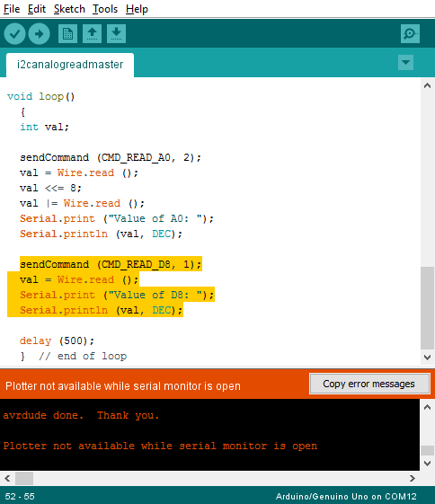
The other thing I changed of course is the pin to which I connect the sensor.
The setup I made is as follows:
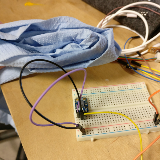
The analog gas sensor is connected to VCC, GND and to an analog pin of the Arduino Nano.
The Nano is connected to the Arduino UNO over I2C, without external pull-up resistors.
I know from the datasheet that this sensor reacts to alcohol fumes, so I used isopropyl alcohol to test its operation.

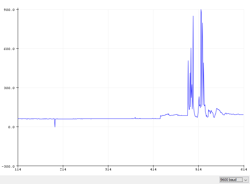
I sprayed some on a piece of kitchen roll, held it next to the sensor and opened the serial plotter to see if I could record spikes in value.
It works! Just look at these spikes every time I come close to the sensor with the alcohol drenched paper!
So I now have the analog sensor value over I2C from one microcontroller to the next. Because both the Nano and UNO run on ATmega328 processors, I now also have the blueprint for my final project as this microcontroller is in the inventory and I know how to make and program boards with it as I previously made fabkit.
OTHER SMALL VICTORY
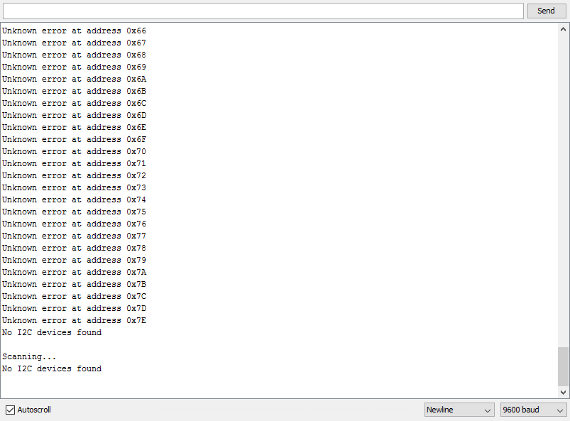
A few weeks ago I had made some boards with I2C devices like a temperature and humidity sensor and an I2C display. However, I could never get them working and could not figure out why. I used the I2C scanner sketch to first of all work out if they were sending data at all, and what I got was this scrambled list of different addresses.
Even though I thought I had checked the board for shorts, I decided to check again and I found that the SCL and SDA line where shorted out. I decided to remove one of the connectors to inspect the traces underneath, and upon close inspection I found that there was a tiny piece of copper shorting out two traces.

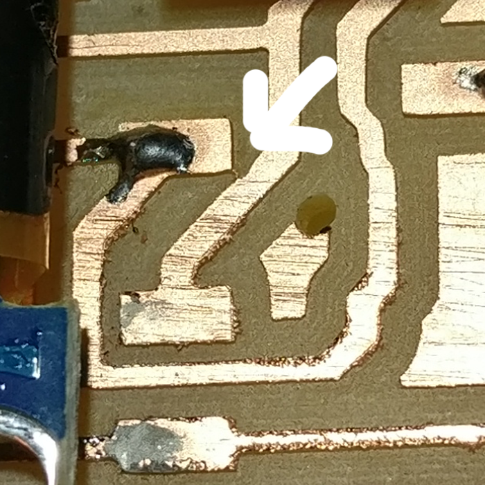
Once I cut this trace it worked perfectly again!
UPDATE 06-25-2017
My local instructor pointed out to me that I didn't complete this week using boards I made myself, which is something I overlooked in the assesment as I used commercial boards.
In my final project however, I use I2C communication between three boards that I made, a board with an ESP8266, one with a temperature sensor and one with an ATmega328 and LEDs.
The full final project documentation which describes my use of I2C can be found here.
Below is an excerpt of my work on I2C from my final project which shows I used this protocol with boards I made to show mastery of this week's skills.
MAKING MORE BRICKS
After making the first brick with the right size and dimensions, I was ready to make other bricks to see if the system of stacking and connecting would work. I decided to start with the toughest one, the LED output brick. For this brick I wanted to:
Fit as many ws2812b LEDs as possible
Drive them over I2C
Make a frosted casing to diffuse the light
First I made the PCB and later I would adjust the casing if needed to this PCB.
MAJOR PROBLEM
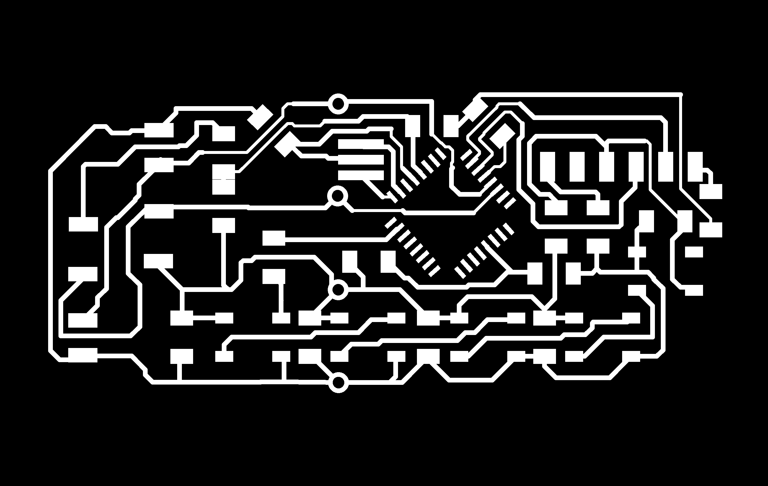
So before I continue I have to tell you about a major problem I ran into, I don’t know how I did it, but something went wrong when saving the files after I had made the board and I lost the layout for the LED brick. I have the schematic and the exported PNG I used to mill it, but the Eagle layout file is lost and therefor I also won’t be able to share it on this page.
That being said, I will show you how I made the brick:
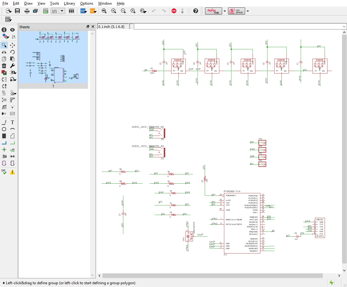
First of all the schematic, I used an ATmega328 to drive the LEDs and translate the I2C signal into a signal the LEDs can read.
To make this board, I used experience I gained during the output devices week, where I already made a PCB and brick with integrated ws2812b LEDs. You can find the documentation about these LEDs and how to use them here.
This is the new schematic I made for this board:
Because I don’t have the layout file anymore, please see this PNG for an idea of how I made the layout:
Because I wanted to optimize space on the board I decided to not include the six pin header to burn the bootloader on the microcontroller. More on that later.
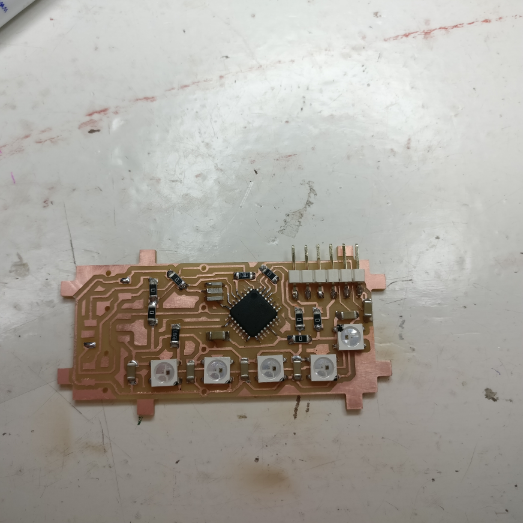
This is how the first board looked after milling:

It all looked fine, but when I soldered the FTDI header on lastly I noticed I had a weirdly placed a capacitor in the top right corner that did not sit well with the FTDI header.

So I took all the components off the board, gave the capacitor a different position and remade the board:(the audio jacks were added later)
Because I want to save space I didn’t include a six pin header to program the ATmega on my LED board and we didn’t have pre-loaded ATmegas from our supplier, so I had to burn the bootloader on a different board.
That is why I designed a programming and debugging board that has no other function than to be as simple as possible which can:
-Burn bootloaders
-Upload sketches via FTDI
-Communicate over I2C
So I made a simple board for the ATmega328 on which I can solder and rework an ATmega to program or test it:
First, you solder the ATmega on:

Then you burn the bootloader using the Fab ISP:

Then you test it by uploading any demo sketch using FTDI:

If everything works you take the ATmega off using a heat gun:

back to the LED PCB
Once back on the LED brick, I programmed a Neopixel library demo sketch and uploaded it to the PCB to check its correct operation.

I laser cut the casing out of frosted acrylic and combined it with a 3D printed top I made using transparent filament:

I didn’t glue it together yet as I might still need to debug and access the PCB.
I2C COMMUNICATION
Because I want to make all the bricks talk to each other over I2C, I needed to do some software and hardware testing.
First of all, as I2C requires a 4K7 pull-up on both the data and the clock line, I needed to figure out if the WeMos board does this internally, or if I should add these to the WeMos breakout board that I made.
To test this, I made an I2C connector on my test board with pads for 4K7 resistors, but I didn’t solder them yet. Instead I just connected the WeMos to the test board and made them communicate over I2C using simple example code.

The code I used to test this is the example code in the Wire library in Arduino IDE is the slave_sender and master_reader.


I used these examples to send data from the ATmega to the WeMos, which worked perfectly, so I knew there was no need for adding the 4K7 pull-up resistors as the WeMos probably uses internal pull-ups.
SENSOR BRICK
The next brick I made is a sensor brick that holds a BME280 temperature and humidity sensor on an I2C breakout. Because the sensor in this configuration already sends an I2C signal I had very little to design on the board of the brick. Except for making it fit the brick and putting on the audio jacks, bottom pads and pogo pins I just added a status LED and resistor to show when it is connected.
These are the schematic and layout:


The first version of the board didn’t have the status LED in the design yet, so I just soldered that on later, but the file you can download does have it.
Assembled it looks like this:

PROGRAMMING
Before glueing everything together I wanted to make sure the code worked, so I had this setup in which I connected the LED PCB and the temperature sensor PCB to the old brick which has a WeMos inside using audio cables.
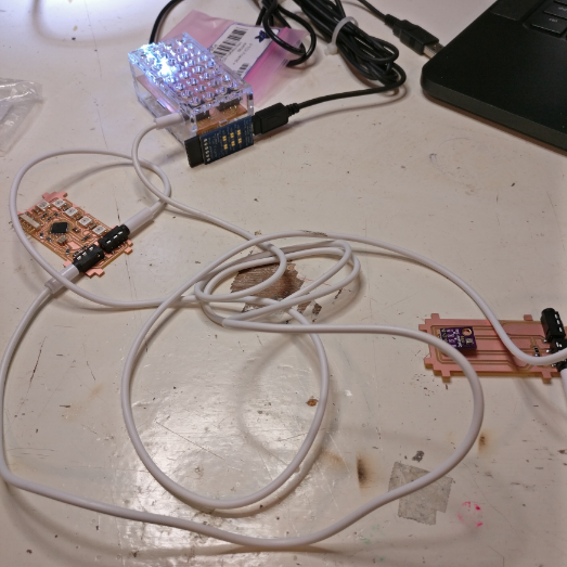
Using these audio cables which carry SCL, SDA, VCC and GND I made a network of three boards that all connect via I2C.
For a full explanation of the I2C code I custom wrote for this, please see my final project page here.
Below are the files for the boards I made for my final project that use I2C in one ZIP folder, these include:
-WiFi board
-LED board
-Sensor board
-Testing and programming board
all Eagle files (ZIP file)

I2C scanner

analog read master
analog read slave