13 - input devices
The output devices week was the perfect week to incorporate in my final project, which is a set of connected Internet-of-Things LEGO bricks. I want to create a hardware and software ecosystem that allows anyone to build their own internet connected sensor kit without technical skills.
To make use this week effectively I first built the first brick for this system, which I won’t elaborate too much on because I will document it once I improve it for the final project. The device I built now is just a proof-of-concept for myself to test the system with.
FINAL PROJECT UPDATE
The way I have my final project planned is that I will use the I2C protocol for the bricks to communicate with each other. There will always be one main brick, the master, and the input and output bricks will be the slaves. The master will have a wireless connection to the internet via WiFi or an IoT protocol and will manage power to all the slaves.
Some of the bricks will just be I2C sensors or devices that I will design a breakout for and some bricks will have a microcontroller to convert an analog signal to I2C.
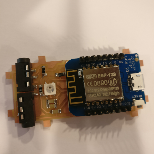
The main brick I made to experiment with consists of a board I made that acts as a shield for a Wemos D1 mini, which is basically an ESP8266 with a breakout and a chip to handle USB communication. I also included a Neopixel on the board so it can indicate it’s state. To communicate with the other bricks I included audio jacks that can be used with audio cables for data and power transmission.(not in any way for audio!)
So with this thing working, I was ready to build an input brick!
CHOOSING A SENSOR
There are so many sensors to choose from, that I started looking for one with the main criterion that it has to have a small footprint because I want to fit it into a small brick.
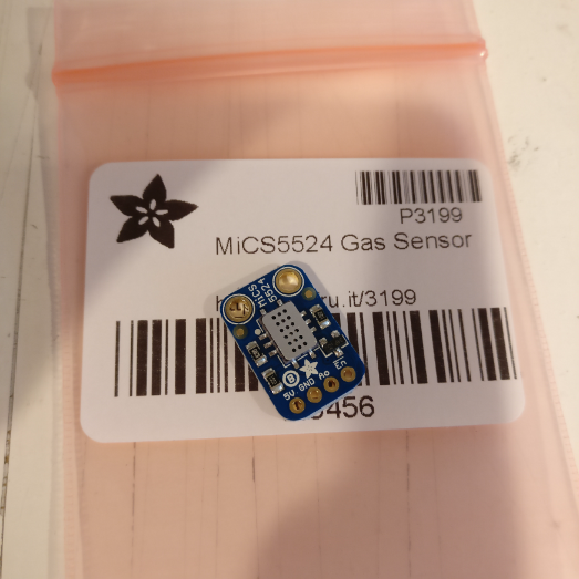
The first sensor I found that I was excited to work with is the Adafruit MiCS5524 VOC sensor that measures various gasses that indicate indoor air quality. You can find it at Adafruit here.
Without going too much into detail of how this sensor chemically works, the main function is that it gives an analog output depending on how much gas it senses.
To hook it up, it needs 5v, GND and analog out.
This sensor is not a dedicated I2C sensor, so in order to make this sensor work on my system I need to convert the analog signal to a digital I2C signal. Now comes a list of (thinking) mistakes I made which took me a long time to figure out:
MISTAKE #1 AVR microcontroller! I immediately went for an AVR thinking that would be the perfect low-cost low-power solution. WRONG! It turns out that finding a small AVR that can do this job isn’t so easy with the Fab Lab inventory. You either over-spec with an ATmega328, or under-spec with an ATtiny44. Instead what I should have done was look for a dedicated ADC ic or breakout. I came to this realization while writing this documentation, way too late to fix it for this week, but this is something I will remember for the next brick I make and my final project.
MISTAKE #2 every microcontroller can do I2C Checking the pin-out of the ATtiny84a, I saw an SCL and SDA output so I thought, easy. I2C should be no problem. Wrong! Some microcontrollers support I2C on a hardware level, and some only through software. The latter is the case for the ATtiny84a, and even then it’s a problem. Here’s what I ran into, when you want a microcontroller to perform an I2C function and you program it in the Arduino IDE, you include the ‘wire.h’ library from Arduino. However, this does NOT compile for the ATtiny series, which I found out only after making the entire board and trying to program it. There are alternatives like the Tinywire library, but after a lot of frustration and not getting it to work I gave up on that, also because I don’t have a lot of experience with I2C code. I’m saving this board for the networking & communications week and then I will tackle it, but this week I just wanted to see some results, so I abandoned that route.
BONUS MISTAKE I also made a board with the ATmega328p because that one does support I2C on a hardware level and works with the wire.h library. So I re-designed the board I made for the ATtiny84A to fit an ATmega328, but after burning the bootloader I could no longer program it. What had happened? I forgot that after burning the Arduino Uno bootloader this board needs to be programmed using an FTDI cable, for which I didn’t include the header because my plan was to program it using the ISP. So that one also became useless.
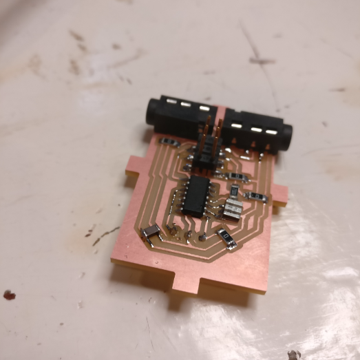
In short what I did was I chose a microcontroller for a job that is more suitable for a dedicated ADC because it eliminates the need for programming etc. I chose a microcontroller that didn’t have native I2C support and my I2C experience isn’t good enough to solve the problem. So what I’ve decided to do is to abandon the board that I made this week and save it for networking & communications week. This is how it looks without the brick casing:
The good thing I took away from this process was the basic dimensions for this board. It turns out this size will fit pretty much every sensor I can think of for my final project and still be compact, so for the next brick I started making this week I kept this size PCB.
NEW SENSOR
To make sure I could get some sensor data coming in this week but still also build towards my final project, I decided to use a simple I2C sensor that measures temperature and humidity. I got a BME280 on an I2C breakout board from Aliexpress.
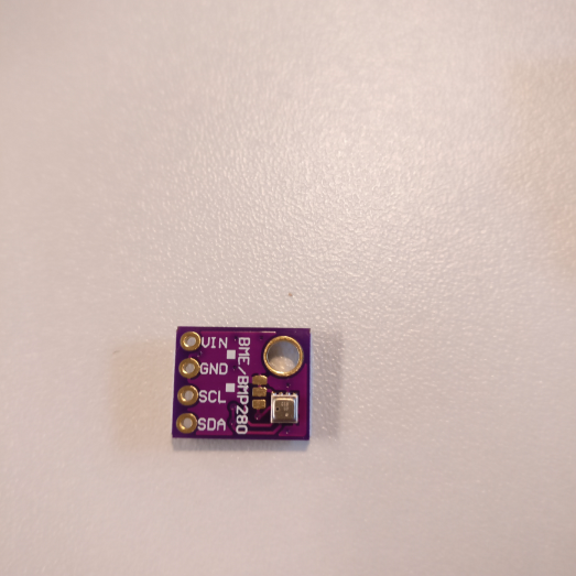
This sensor measures temperature and relative humidity, but I’m only doing a temperature measurement with it this week.
The pins this breakout has are:
VCC
GND
SCL
SDA
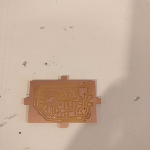
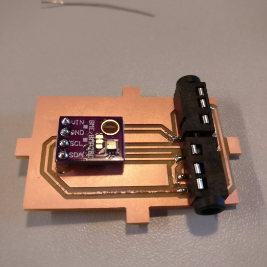
I made a simple breakout board that allows me to link this sensor to my audio jacks and make the whole package fit the brick concept.
The layout looks like this:
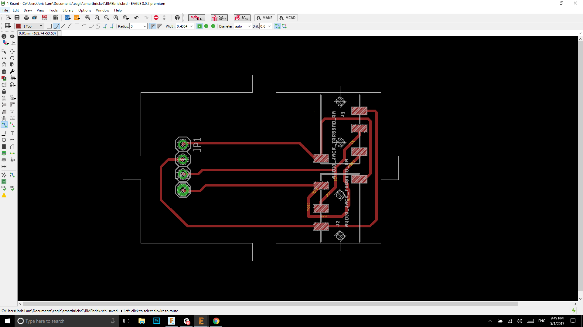
And the finished board like this:
SETTING UP THE ESP8266
Because I’m just connecting an I2C sensor to my main brick which runs on an ESP8266 I only needed to write code for the ESP(Wemos) and not for a slave brick.
To get started with the Wemos D1 mini / ESP (same thing, Wemos is just a breakout with USB) I found this tutorial which tells you how to setup the hardware using the Arduino IDE.
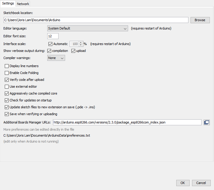
Before you can do any coding, you need to add the Wemos to your boards in the Arduino IDE, which you can do by going to preferences and adding this link to the additional boards manager URL tab
http://arduino.esp8266.com/versions/2.3.0/package_esp8266com_index.json
Then under tools/board/boards manager, search for Wemos and you should be able to install the entire ESP family which is this one:

CONNECTING THE SENSOR TO THE BOARD
The board I use to connect the sensor is a board I made on which there is an ESP8266 module.
The sensor sends an I2C data signal via an audio cable to my board where the ESP8266 picks it up on pin D1 and D2.
I made a microcontroller board which only has three functions, one is I2C communication, two is WiFi connectivity and three is a status LED to indicate it's status:
The two are connected using an audio cable.
CODE
(6-12-2017 UPDATE)
The mentioned library below is now abandoned, you can still download it via my GIT page which is linked below, but I'm no longer working on it. Alternatively to make this sketch work you can use
Adafruits BME280 library which you can find here.
Together with a friend who is a guru Arduino coder I’m working on a big library for the smart bricks which is a quite big work-in-progress. Because it’s still heavily under construction I won’t go into detail on how this whole library is set up because it’s likely to change completely, but instead I’ll explain the code needed to read this particular temperature sensor.
If you want to look around the library or download it, it’s available on my personal Github repo here: https://github.com/ULTRAIoT/SmartBrick
The sketch I want to write should simply read the sensor and give the values via the serial monitor of the Arduino IDE.
The libraries needed for this are
Smartbrick.h(only in my case, not strictly neccesary)
wire.hstandard in Arduino IDE
adafruit_BME280.h
These libraries are included in the Smart Brick library, all you need to do is open the folder with external libraries and copy them to the Arduino libraries folder.
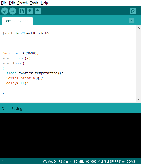
Because of the libraries the code for this sensor couldn’t be easier, take a look:
Let’s break it down:
The #include
Smart brick(9600); sets the baud rate at 9600.
void setup can be left empty, the library deals with that.
float g=brick.temperature(); turns the temperature reading brick.temperature, which also comes from the library, into a floating point named g
Serial.println(g); is a very simple command that tells the device to send a serial value to the serial monitor
delay(100); slows the whole thing down a bit
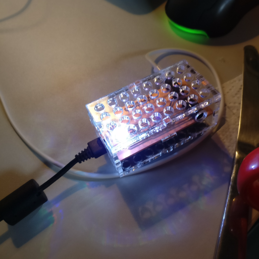
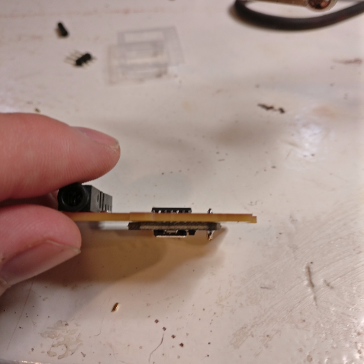
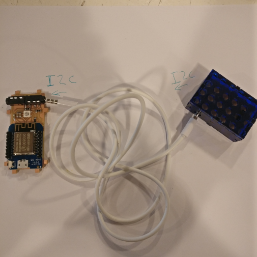
After uploading the code to main brick via USB, it is ready to connect to the sensor brick via an audio cable I use to transmit data and power.
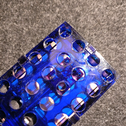
I laser cut a case for the sensor board which now looks like this:
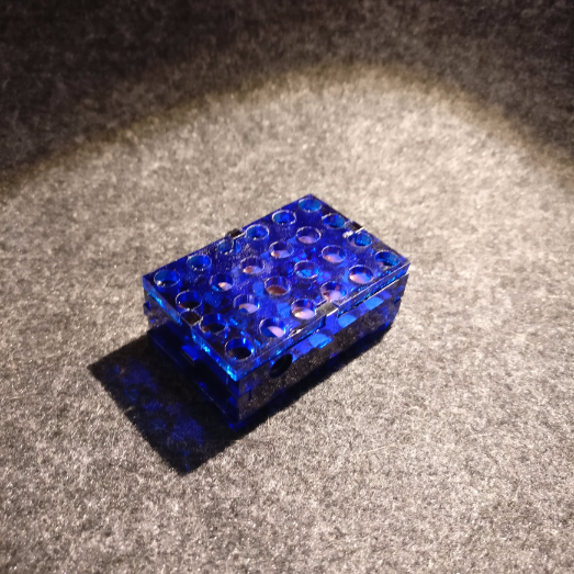
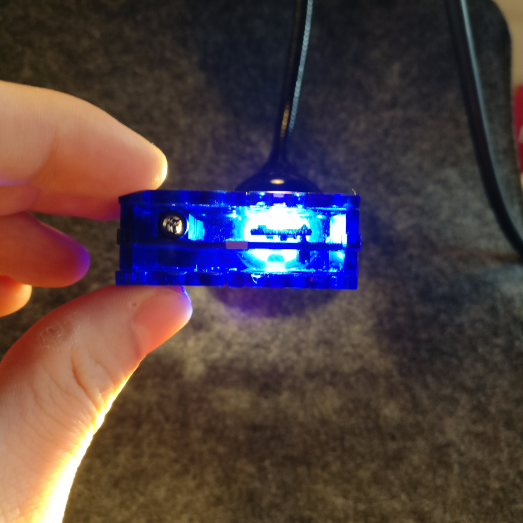
Together they look like this, the plan is to make a connector that allows them to also be stackable but that needs more development. It’s good noting that the sensor brick has two audio jacks which allow it to be linked with other sensors that all communicate over the same I2C line.

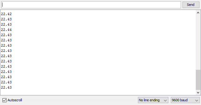
SERIAL MONITOR AND PLOTTER
When the two bricks are connected to a computer and the Arduino IDE is running, under tools you can click the serial monitor to see the data coming in.
At my office where I’m testing this, it is a very stable 22 degrees celsius, which the values clearly show.
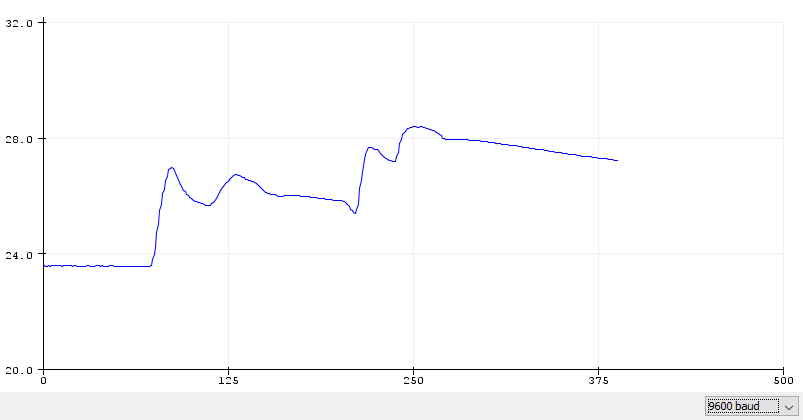
There is also the option to choose the serial plotter, which turns the data into a graph, what you see here is me blowing into the sensor at certain points, and then it clearly shows that the temperature shoots up.
CONCLUSION AND LEARNINGS
In conclusion, building an I2C system isn’t as easy as just reading out an analog sensor on an analog input pin and converting it to I2C. What I will definitely do better next time is research the microcontroller more before I choose to work with one, and really think about what it is that I need it to do. In this case I just wanted to use it as an ADC, so why not then just use an ADC. I think because these cheap microcontrollers are so powerful and do so many different things it’s very tempting to just use one for every job, but I need to think more about it’s purpose.
sensor board Eagle schematic

sensor board Eagle layout
WeMos board Eagle schematic
WeMos board Eagle layout
Arduino sketch