
Week 11. Machine design
During this assignment, we fabricated in a group a machine to move liquid between different containers.

Tasks
- Automate the machine we built in Week 9
- Document the group project and my individual contribution.
Process explanation
Project overview
The project is documented in our group page
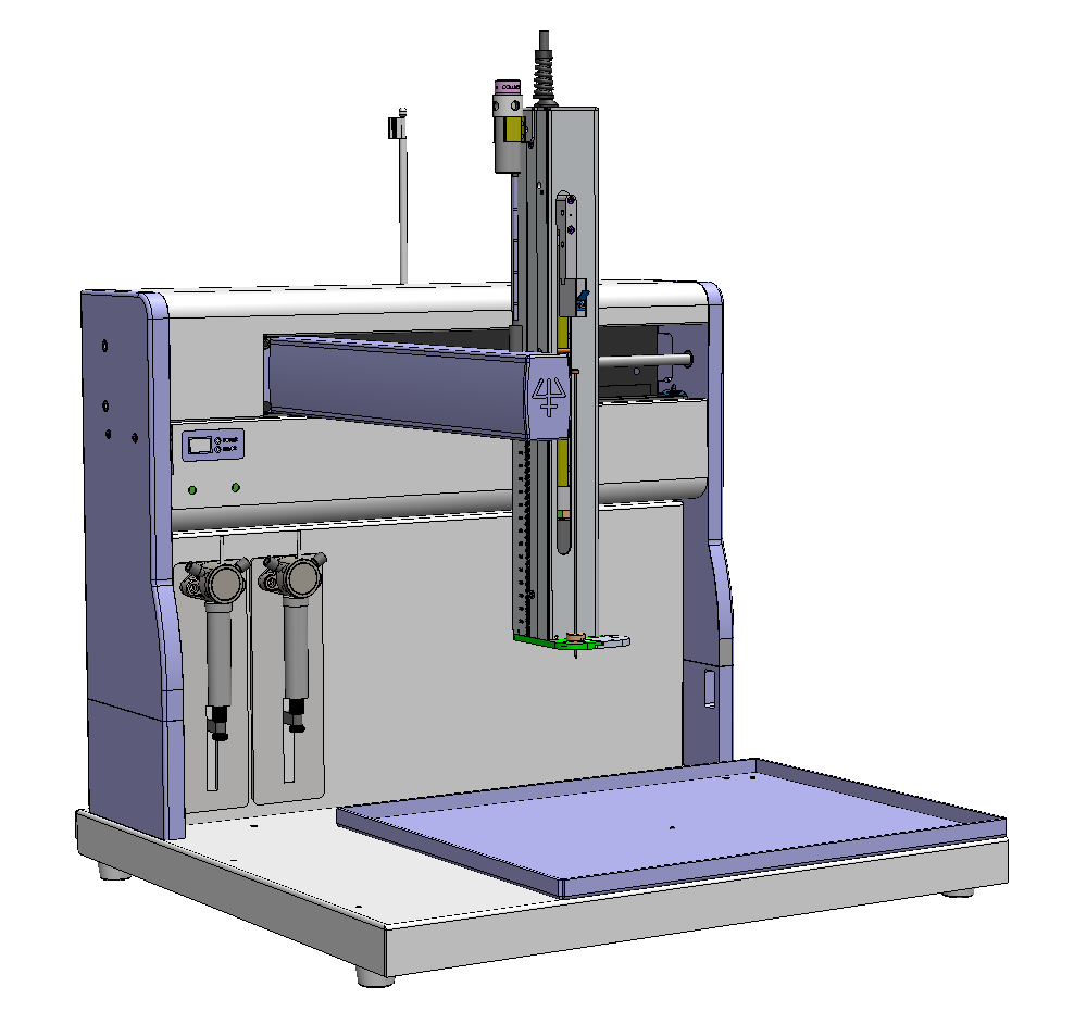
We decided to make small changes to the original design of our liquid handler. We decided to remove the rotational phase, and instead use three different linear phases, one per axis, that is one for move in the X axis, one for the Y axis, and one for the Z axis. We got the inspiration from the Gilson GX-271 Liquid handler. The machine can be seen in Figure 1. In addition, Figure 2 shows a 3D model of the same machine where the three linear phases are clearly visible.

Own contribution
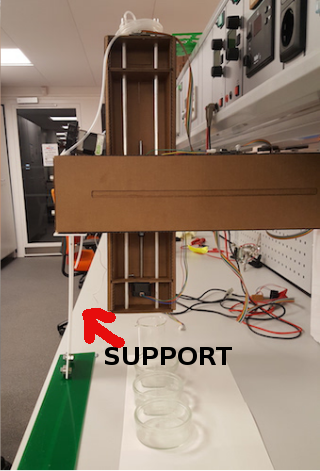
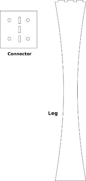
The new structure needs a support that make possible to move in the Y axis. Otherwise, the arm could not support the weight and will fall down. The support is shown in Figure 1.1. The support consist on two pieces, the leg and the connector with the machine arm. The machine arm is and the support is connected through bolts while the leg and the connector use press fitting technique. I designed the support directly with Inkscape. The design is shown in Figure 1.2.
We decided to use Gestalt modules as suggested by Nadya. Gestalt modules uses FabNet network. Fabnet is essentially an RS-485 bus with a few additional power signals (one to drive motors that supports up to 24V, while the other is used for the logic circuits with up to 7.5V).From the previous link I read that:
Fabnet is a multi-drop network, meaning that multiple modules (a.k.a. nodes) share a single set of communication wires.
Signalling is differential based on the RS-485 specification. Each node is assigned a four-byte IP address which uniquely identifies it over the network.
Besides communication, Fabnet provides power at two voltages: high voltage (12V - 24V) is intended to drive motors, lamps and actuators, while low voltage (7.5V) supplies power to the logic circuits of the nodes.
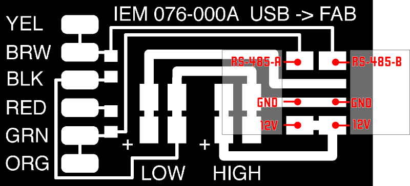
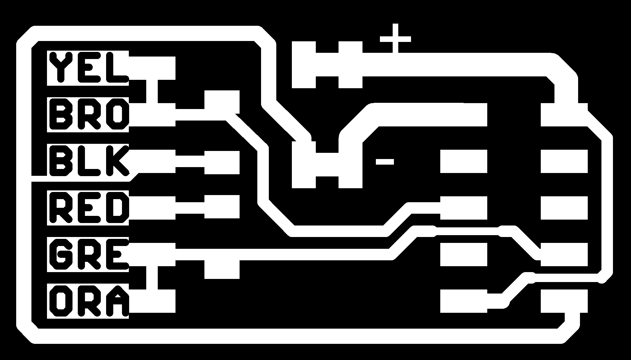
The pinout of the RS-485 is shown on Figure 2.1

The pinout of the Fabnet is shown on Figure 2.2

We need to create a USB-to-RS-485 converter. We followed the instructions from this page.
I initially milled the circuit on Figure 3. But I realized that I could not use the ribbon cable as it is for that connection and I should either modify the cable or the board. I finally, milled the board shown in Figure 4.
After that I started testing how the gestalt modules work utilizing just one stepper motor. I first cloned the gestalt modules repository (Figure 5). Then I had to install the python gestalt libraries: sudo python setup.py install(Figure 5)

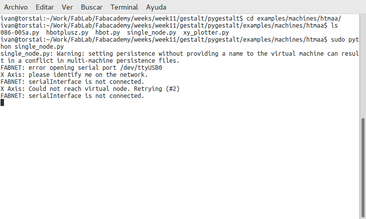
As I wanted to test just one motor, I searched for an adequate code example. I found it at : examples/machines/htmaa/singlenode.py. I run it (without connecting yet the USB) and the code run correctly (Figure 6).
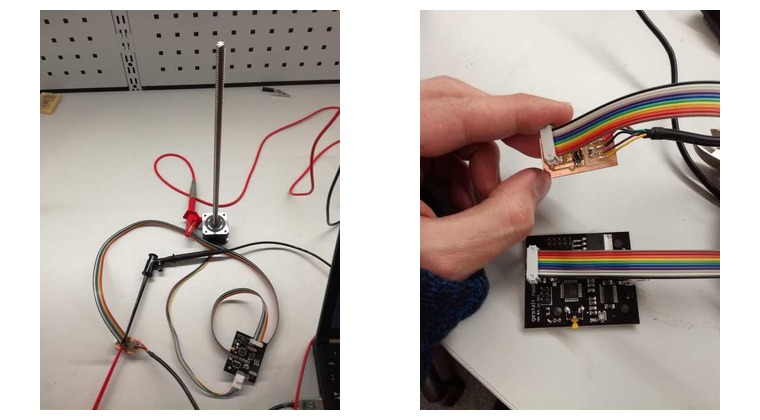
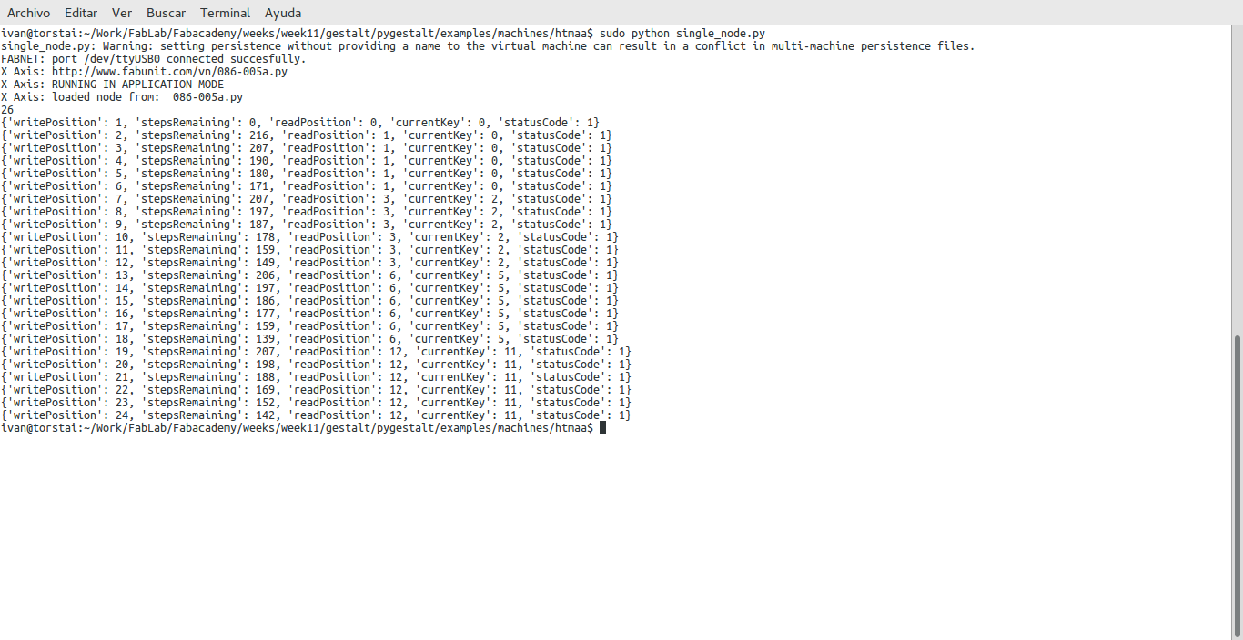
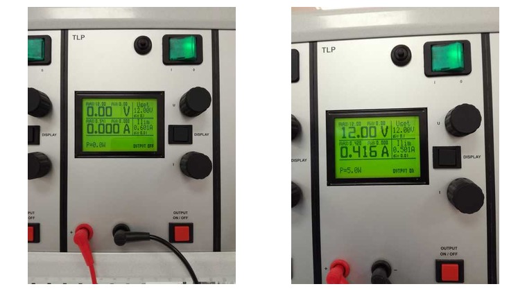
After that I set up the whole system, that is, connected the gestalt module to my computer using the USB-RS485 adapter. The Gestalt module is connected to the motor (Figure 7). I connected the adapter to a power source (12 V with a limiting intensity of 600 mA).Then I run the sudo) and after pressing the gestalt module button I got the message on Figure 8. The motor started to move as expected.
I checked that the power consumption for one motor was around 5 W (Figure 9)
Resources utilized
- Machines that make: cardboard stages
- Steps motors, rods
- Inkscape to trasnform the content to SVG.