Video in repo.
Week 9: Mechanical Design
Brainstorming Project Idea
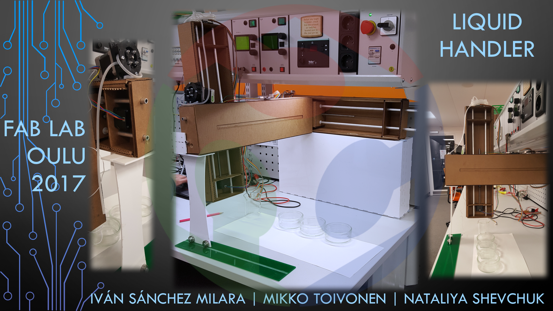
To come up with an idea for the project we hypothesized what trends are likely to be influencing FabLabs in the future. Mikko's guess was that a stronger emphasis will be put on bioengineering so the Labs will require equipment for chemical analyses. As a result, we decided to give a try constructing our own a Liquid Sampling Apparatus.
We got our inspiration from a Fabacademy 2015 project made at WeMake Fablab. Their project was a A Granatina machine that integrate a syringe aspiring and releasing liquids to be moved from one point (a glass) to an other (an other glass) and make the mix. Our idea went a little bit further, since we want to be able to move liquids from/to different containers. To that end, we needed a rotating board to place the different recipients and a linear stage to move the nozzle backward and forward.
Design
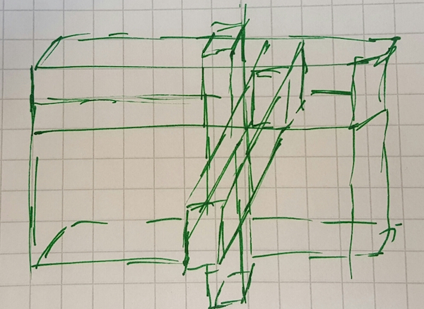
We decided that the machine will be moving in two planes to draw and shift liquid samples among containers placed on the rotating tray.
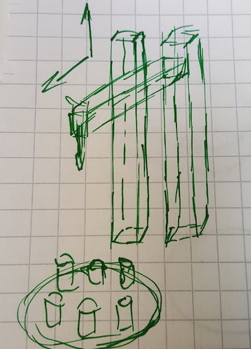
Therefore, the Liquid Sampling Apparatus needs the following components:
Making and Assembling
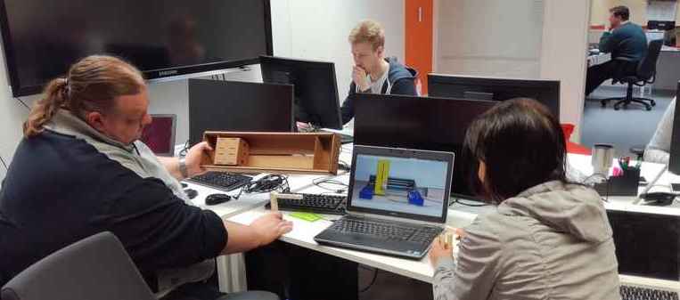
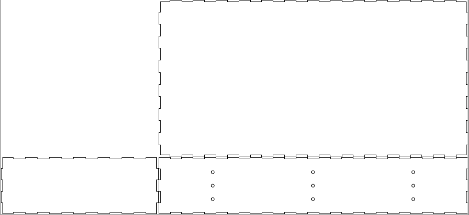
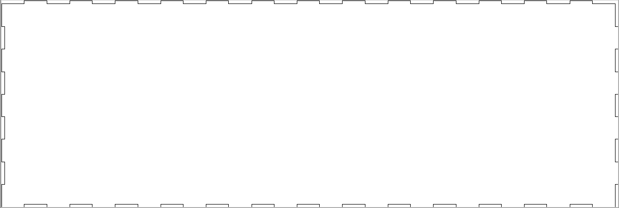
For lasercutting the modular stages, we used cutfiles for the SCIENCE cardboard designed by Nadya Peek (Machines that make: cardboard stages). The peristaltic pump design for 3D printing was taken from Thingiverse. Iván created a design for lasercutting the cardboard part of the rotating tray, and Mikko made a design for 3D printing axel mount to attach the tray to the motor.
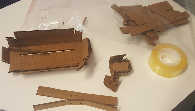
We initially tried to make a small version of the machine, so we scaled all the pieces from Nadya's model to A4. We used a cardboard of aprox .15'' thickness. However, when we tried to mount it, the A4 model was just too small because the flaps were so thin that they easily broke. Furthemore, we did not scale correctly the material thickness.
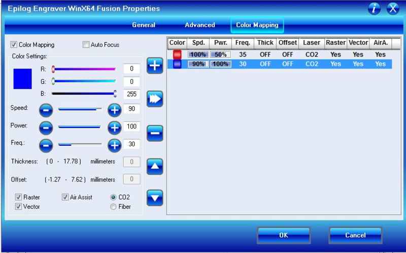
We finally borrowed the files from Eino, who is in the other group at FabLab Oulu, since we could not scale files correctly ourselves and we were just running out of time. Before printing we had to set up the laser cutter so it cut the blue lines out of the cardboard while leaving the red lines engraved just to mark the folding. The cutting speed was set to 90%, power 100% and frequency 35% for blue lines and the speed was 100%, power 50% and frequency 30% for the red lines. In addition, Nataliya and Iván had to modify the faces_up file. Since the central box is connected to two different arms, we had to make connection holes in both sides. In addition, we had to mirror one of the sides so the bolts can be attached correctly. The files we used can be found here
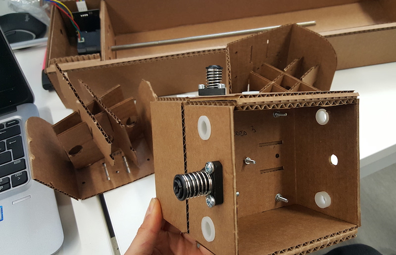
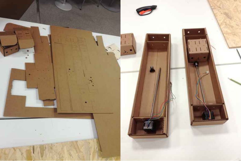
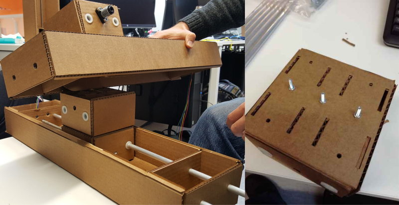
We then mounted one linear stage, just to understand better the real needs of our design and how the different stages could be assembled together. We checked different examples from previous years' project.
After that we assembled the other two linear stages.
When starting connecting the stages, we realized that we have to modify alignment slightly of the holes in the inner cardboard box of the middle horizontal stage so that it can be attached to the other two inner cardboard pieces of the vertical stages. Basically we had to rotate the holes for the bolts. The inner pieces are connected with the screws.
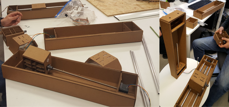
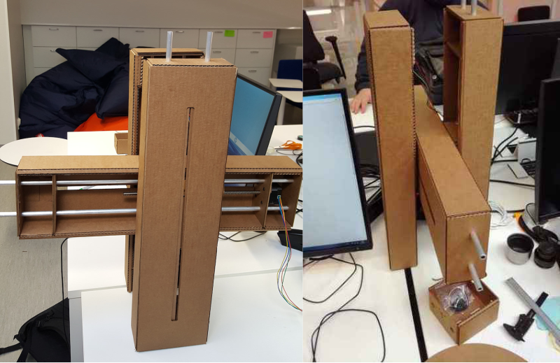
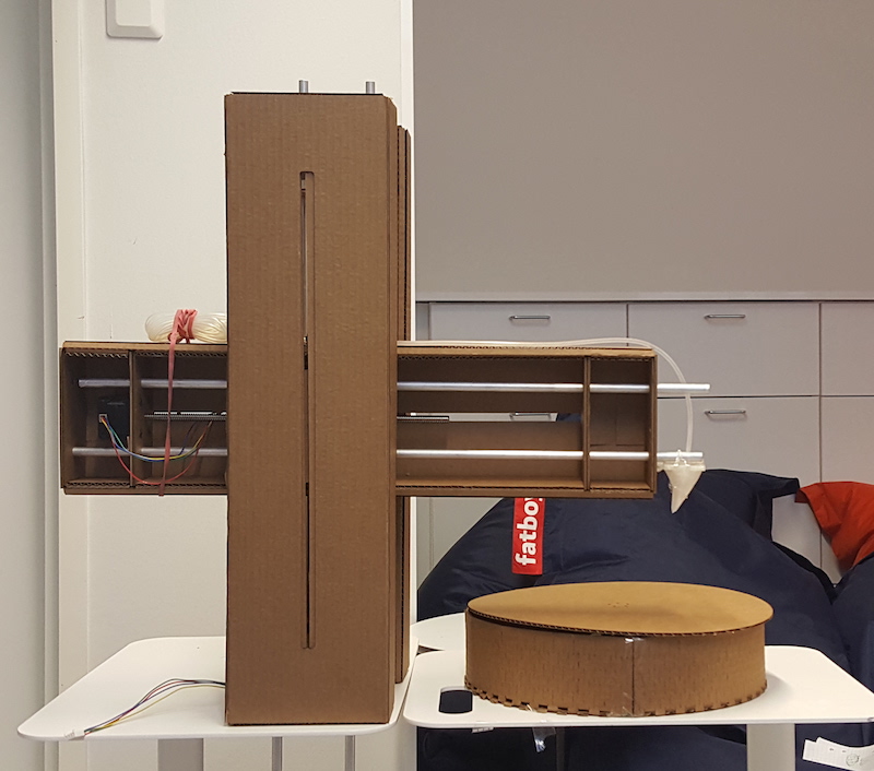
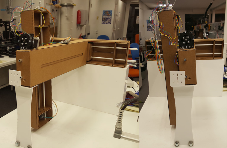
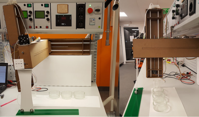
This is our final version of the machine after assembling the tree linear stages together.
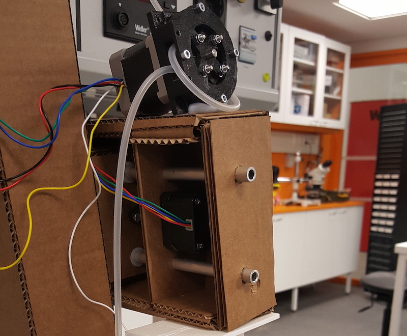
The pump and the axel mount have been 3D printed.
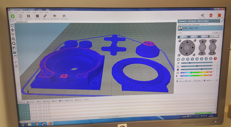
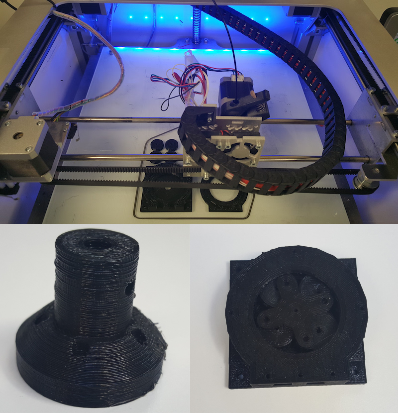
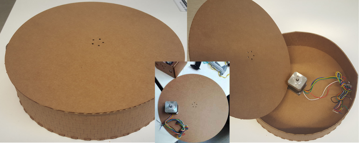
Finally, we just need to mount the rotational stage. We basically built a disc that contained a step motor inside. The motor was connected to a circular tray, that permits the rotation of the liquid container. The disc was made out of cardboard in order to test the feasibility of the stage. We utilized the Inkscape Elliptical Box Maker as a base to build this stage. The stage was built out of 4 parts. The base, two semicircunferences for the lateral walls and and a cicular lid that will rotate. The base and the lateral walls were connected via tabs. The center of the tray had a hole to accommodate the motor. The motor should be connected to the lid via bolts. The height of the walls were the same as the height of the motor. We had to cut several models till the measurements were correct and the hinge lines permit correct bending without breaking the material. We did not have time to test carefully the state, but initial tests shown that the material is not the most adequate one for this stage. It is not consistent enough.

We tested manually and confirmed that the stages can move in two planes like initially intended.
Week 9 Summary
Week 11 To-Do List
- The material for the rotating phase is not good. We need to choose stronger material than cardboard.
- Made a base where the linear phase and the rotational phase stays together. In this way, we do not need to recalibrate the machine positions every time we set the machine up.
- Increase stability of the machine.
Week 11: Machine Design
As we further researched what has been done before, Mikko found out that commercial versions of this mahcine are called Liquid Handlers. Learning more about these machines, we realized that we need to modify the design, reassemble the machine and connect the stages in a different way. Also the machine will require a supportive structure.
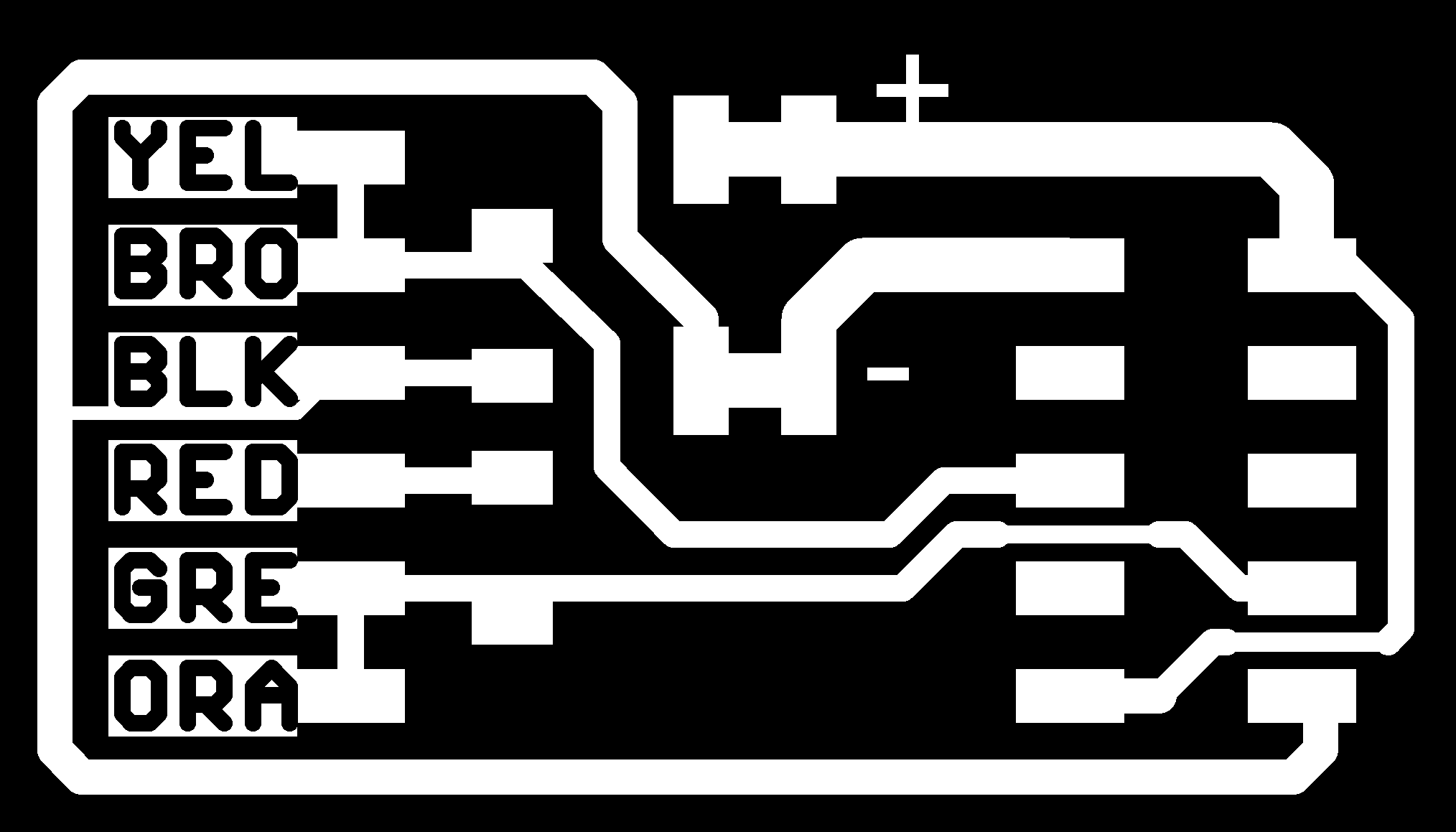
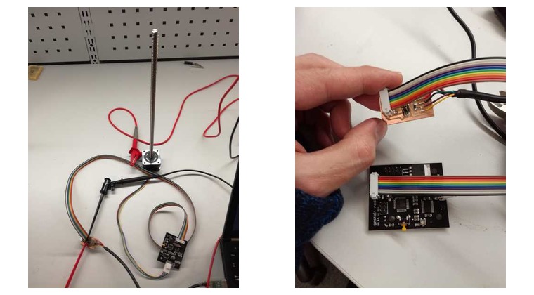
We used Gestalt modules based on the FabNet network. We had to create a USB-to-RS-485 converter and inially we chose the board design found in the FabAcademy Tutorials.
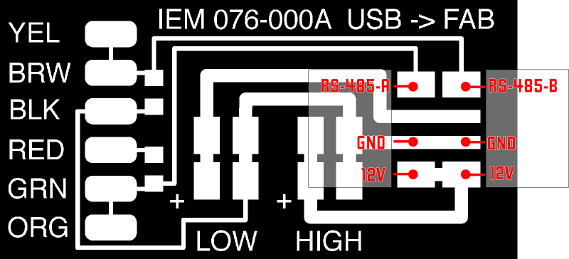
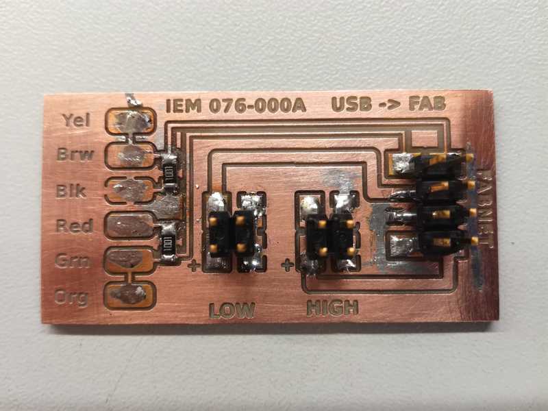
After the board was milled and stuffed, we realized it cannot be used with the ribbon cable, so instead of modifying the cable, we made a new board designed by Bas.
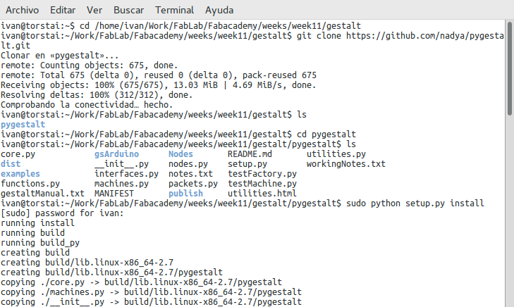
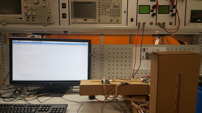
We started setting up the software with Linux. Iván cloned the pygestalt repository, switched to the correct repository, and ran setup.py to installation.
sudo python ./setup.py install
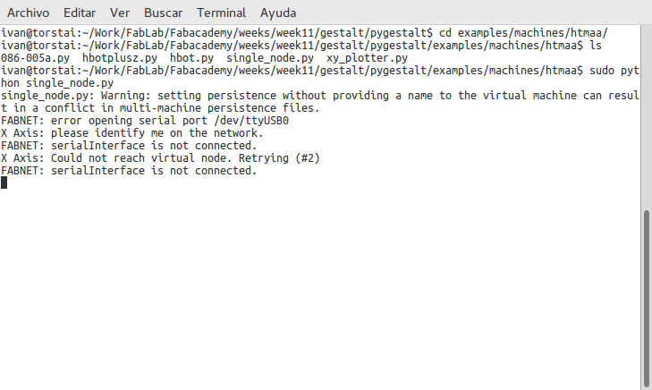
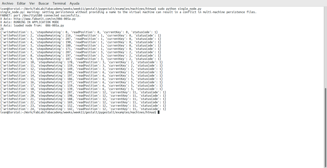
Then we wanted to test one motor only, so we used code from examples/machines/htmaa/singlenode.py. We ran it yet without connecting the USB.
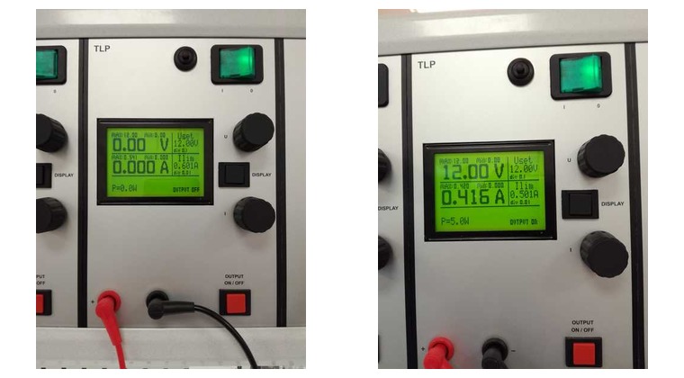
After, we connected the Gestalt node to the computer using the USB-RS485 adapter and to the motor. The adapter was connected to a power source (12 V with a limiting intensity of 600 mA). After running the singlenode.py as a root user (using sudo) and pressing the Gestalt module button, the motor started moving as expected. Power consumption was about 5W
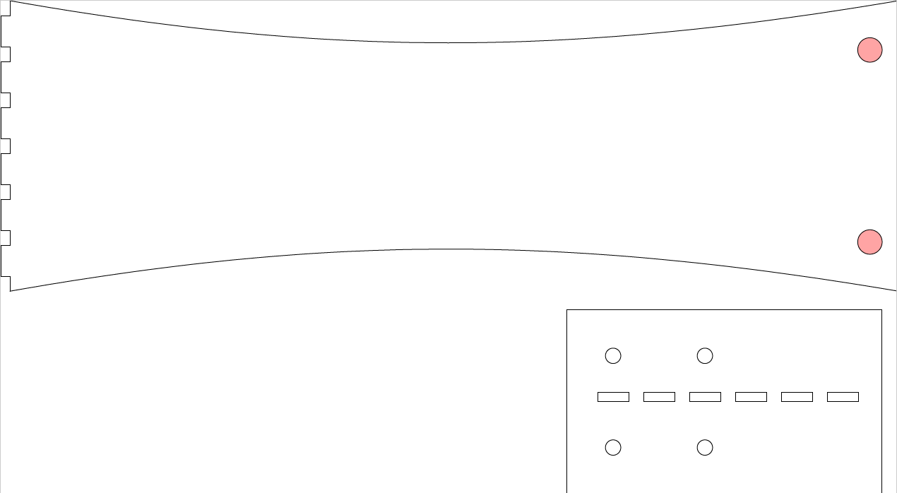
To proceed, we had to make the support structure and reassemble the machine according to our updated design. The support was designed in Fusion 360 and in Inkscape and lasercut as interlocking 3mm thick acrylic parts. A part of the inside box of the X-axis stage was also redesigned and replaced to fit the metal poles of the Y-axis stage. Iván made the initial design of the whole supportive structure (lateral and main parts). Mikko suggested to modify the support to add wheels to the moving part. So Nataliya and Mikko edited Iván's design. All of the files for the support can be found here.
When the machine was reassembled, we tested each axis separately. We had to reconnect cables several times to get the right connections and be able to identify all axes. We utilized Nadya's single_node.py example that can be obtained from Nadya's pygestalt github's project, in the following path: pygestalt/examples/machines/htmaa/single_node.py
After that we utilized Nadya's fabnet_xyaxes.py example that can be obtained from Nadya's pygestalt github's project, in the following path: pygestalt/examples/machines/mods/ as a base to write our code. We did the following changes:
Add a new node to the node list, in this case the Z axis. Append also this node to the compound list
self.zAxisNode = nodes.networkedGestaltNode('Z Axis', self.fabnet, filename = '086-005a.py', persistence = self.persistence)
    self.xyzNode = nodes.compoundNode(self.xAxisNode, self.yAxisNode, self.zAxisNode)
Set the coordinates system to mm
self.position = state.coordinate(['mm','mm','mm'])
Set direct drive in all axes:
self.stageKinematics = kinematics.direct(4) #direct drive on all axes
In the initFunctions activate all the 3 axis:
self.move = functions.move(virtualMachine = self, virtualNode = self.xyzNode, axes = [self.xAxis, self.yAxis, self.zAxis], kinematics = self.stageKinematics, machinePosition = self.position,planner = 'null')
Modify the speed from 2 to 4
stages.xyzNode.setVelocityRequest(4)
After that we calibrate the machine, and we realized that the maximum value reachable by any of the 3 axis is 300
# X axis, positive moves left max 300


    # Y axis, positive brings front max 300


    # Z axis, positive moves up max 300
After the first testing of the axes automation, we modified the initial support design of the Y-axis, since it was not providing enough stability for the machine to move on its own.
Then we set up another connection for the pump motor. After making sure it is working with the single_node.py code, we connected it to the machine and identified it in the code as the fourth axis. We modified the code accordingly, obtaining the following code.
With the further automation testing, we tried different combinations of moves by adjusting coordinates and velocity in the code to come up with the sequence of moves for the final presentation.
Although the peristaltic pump is fully integrated in the machine, and the motor makes correct movement, we did not manage to get the suction working. We assumme that we had some minor issue with the design.
Opportunities and Future Development
The interest of developing biology equipment at Fab Lab is increasing. It permits slushing prices and making expensive biology equipment available to research groups without extensive expenses. The machine that we built during this week is one step forward in that direction. Liquids handlers are very used tools in any biology lab. We managed to create a working prototype of one liquid handler (with the exception of the suction in the peristaltic pump). After we will manage to integrate the suction, we might cooperate with the biology department the future development of the project by presenting the machine, letting them try it out and discuss possible improvements. When we understand better the needs of the department, we could create a second version of the machine integrating the preferences of biologists and biochemists. The next version might be delivered to our university's biology lab to be used there. We might make small modifications to the machine based on their feedback. Finally, when we get a prototype useful enough for the local needs, we could make the design available to all Fab Lab community. After that, we could think about building new machines in collaboration with biology and biochemistry researchers. Our goal is to build machines, useful in any biology lab, and that can be fully built at Fab Lab, reducing the need of buying components when possible.
Files:
Parts of the machine including original and modified designs for the cardboard stages (NOTE: The faces_down was borrowed from Eino, our Fab Lab colleage, the faces_up had to be modified by us), support structure for the machine, the circular stage that was not used in the final development (week 11), as well as the lid,source code for automation, local settings and virtual machine persistent files