- test the design rules for your printer(s)
- design and 3D print an object (small, few cm) that could not be made subtractively
- 3D scan an object
Group Assignment
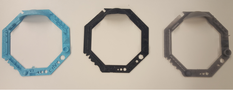
Together with Jari, Iván, and Mikko, using the Test your 3D printer! version 3 design, we tested three 3D printers currently available in our lab:
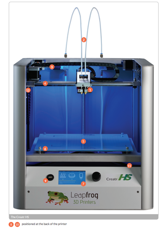
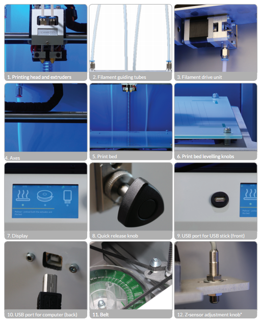
- Leapfrog Creatr HS (1)
- 3D printer by Mikko (2)
- Form2 (3)
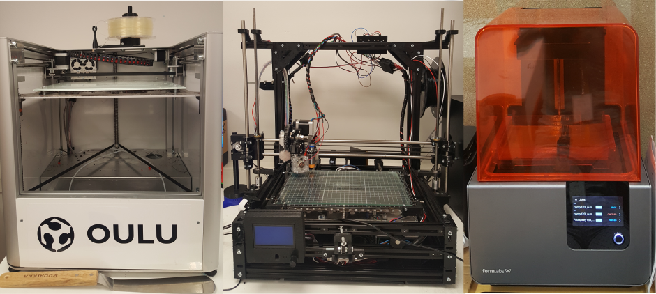
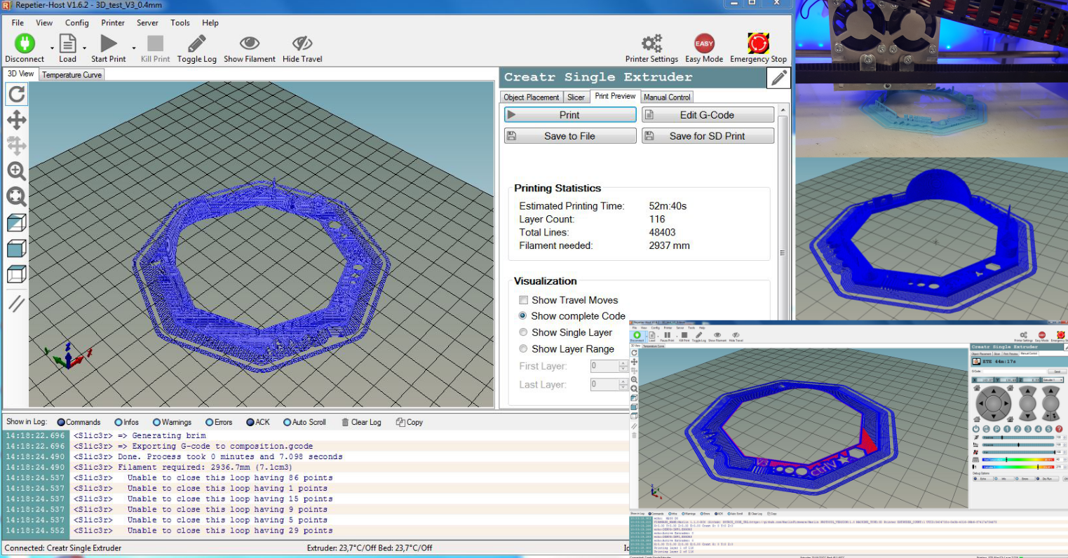
To prepare designs for print, we used .stl files, Repetier-Host for Windows V1.6.2 (printers 1 and 2), and PreForm Software 2.10.3 (printer 3)
Thank's to Mikko not only for the printer but also for volunteering to help everyone get familiarized with the 3D printing hardware and software.
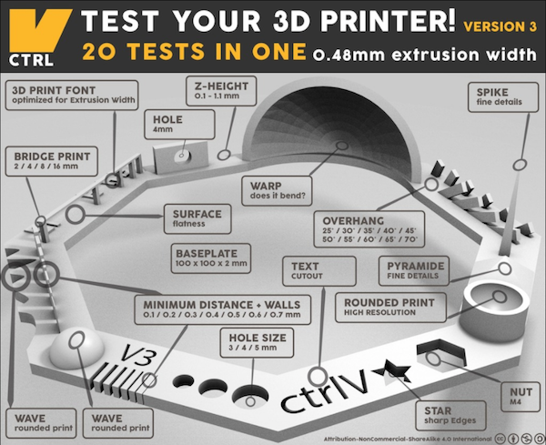
Here are the result and the summary of the testing
| 1 Blue | 2 Black | 3 Grey | |
|---|---|---|---|
| Nut, Size M4 Nut fit | + | + | + |
| Wave, Rounded Print | + | + | + |
| Star, Sharp Edges | + | + | + |
| Text Cutout, Complex Shapes | legible | legible | + |
| Holes, Size 3, 4, 5 mm | + | + | + |
| Minimal Distance: 0.1, 0.2, 0.3, 0.4, 0.5, 0.6, 0.7 mm | + | one wall failed | one wall failed |
| Z height: 0.1, 0.2, 0.3, 0.4, 0.5, 0.6, 0.7, 0.8, 0.9, 1.0, 1.1 mm | lowest step failed | lowest step failed | lowest step failed |
| Wall Thickness: 0.1, 0.2, 0.3, 0.4, 0.5, 0.6, 0.7 mm | + | one wall failed | one wall failed |
| Bridge Print: 2, 4, 8, 16 mm | + | not clear | + |
| Sphere, Rounded Print 4.8mm height | + | + | + |
| Sphere Mix, 7 mm height | + | + | + |
| Pyramid, 7 mm height | dull tip | dull tip | + |
| Overhang: 25, 30, 35, 40, 45, 50, 55, 60, 65, 70° | shapes not clear-cut | shapes not clear-cut | + |
| Warp, does it bend? | + | + | + |
| 3D Print Font, optimized for 3D printing | |||
| Surface, Flatness | + | ||
| Size, 100 x 100mm x 23.83 (10mm width) | + | - | + |
| Spike, minimum Layer Time, 21 mm height from Bottom (include Baseplate) | not clear-cut | not clear-cut | + |
| Hole in Wall, 4 mm diameter | + | + | + |
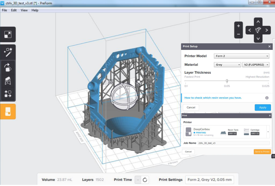
We also printed out some of our Individual assignment designs in Form2, which again proved to produce the most detailed 3D prints.
Individual Assignments
Designing and Printing a 3D Object
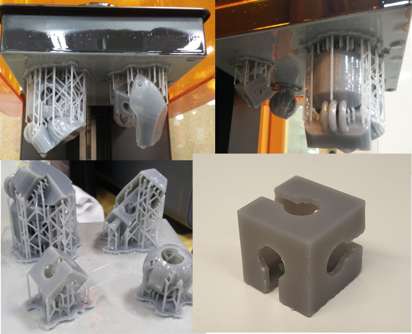
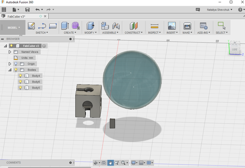
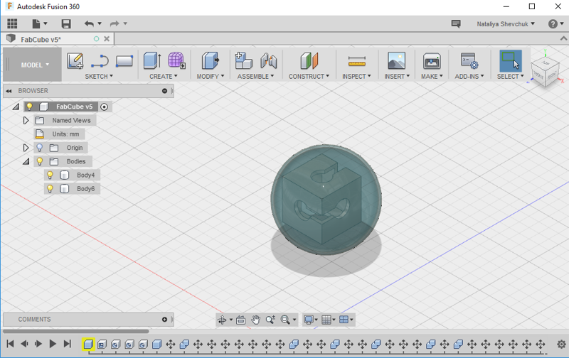
I used Fusion 360 to make a 3D design that cannot be made subtractively - a cube with pattern inside a sphere. I draw a cube with 20mm side and a sphere with the 40mm diameter. Both figures were made empty inside - the "shell" thickness is 1mm. Holes (10mm in diameter) were cut in the cube, and the rest of the pattern on the cube was created by cutting off areas with another box shape. Commands used: Create - Box, Create - Sphere, Modify - Shell, Create - Hole, Modify - Combine - Operation - Cut.
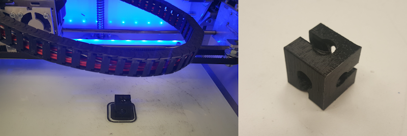
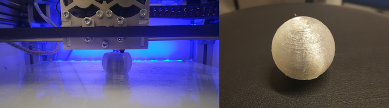
First, I printed the cube, then I printed the sphere. When the sphere was about 70% done, I paused printing to insert the cube. Due to the lack of support structures, some parts of the cube did not come out clear-cut, but, overall, the 3D design ended up in a decent 3Dprint.
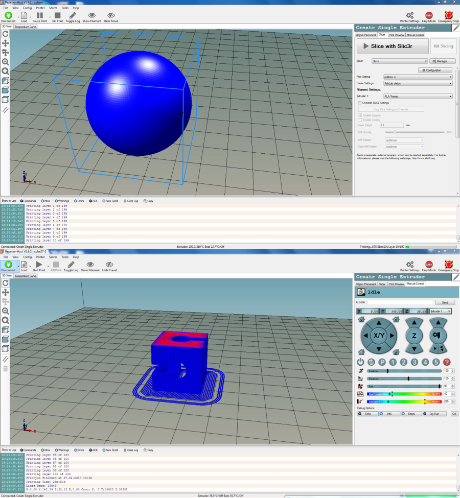
To get to know about 3D printing with the Leapfrog printer and using the Repetier and the Slic3r software, I referred to the online guides. First, I overviewed the Leapfrog's manual.
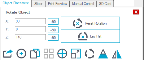
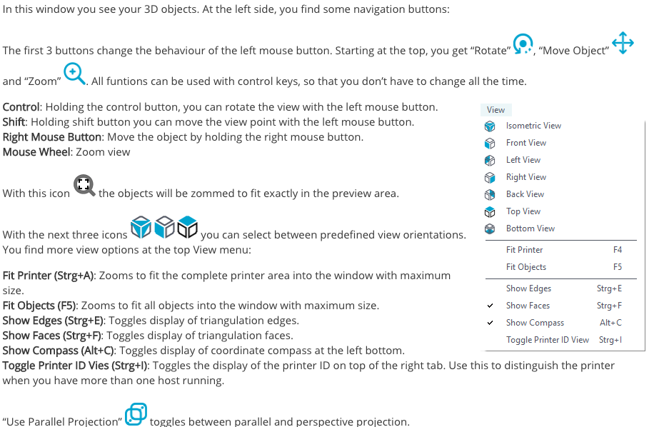
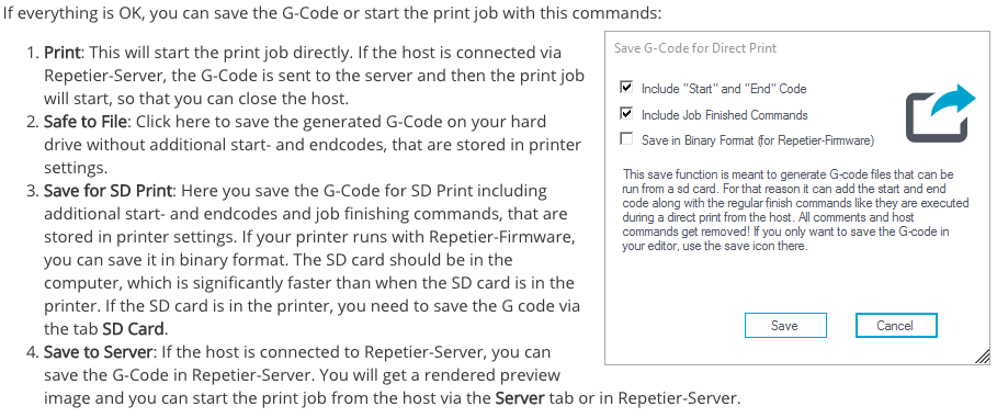
Next, I reviewed the host software compatible with our Leapfrog 3D printer, the Repetirer. The software guide offers a 4-step printing process:
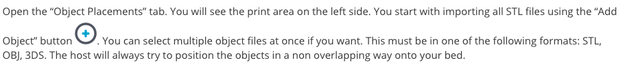
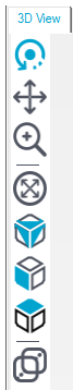
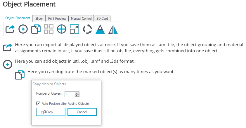
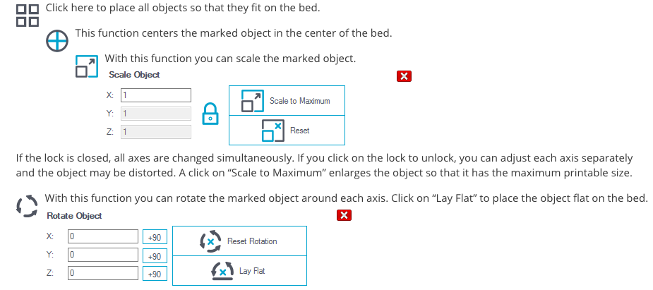
- Object PlacementImport one or more 3D models and place, scale, rotate or duplicate them on your virtual bed.
- Slice your plate with different slicers and optimal settings for perfect results.
- Preview check the result completely, in regions or layer by layer.
- Print directly from the host via USB or TCP/IP connection, via SD card or via Repetier-Server.
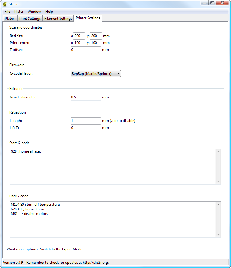
Slic3r is used in combination with Repetier, has two modes of operation, Simple and Expert. These may be chosen from the Preferences window (found under the File menu). Simple mode offers a reduced set of options, enough for the beginner to get started with. Expert mode give more control over how Slic3r produces the G-code.
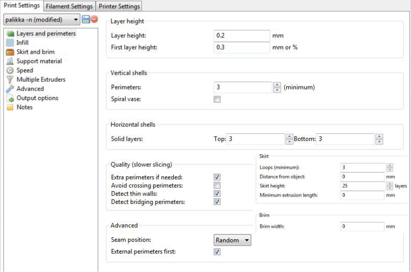
The Print Settings tab provides the opportunity to change settings related to the actual print. Whereas the other tabs are changed rarely, the settings on this tab will be modified regularly, possibly for each model printed.
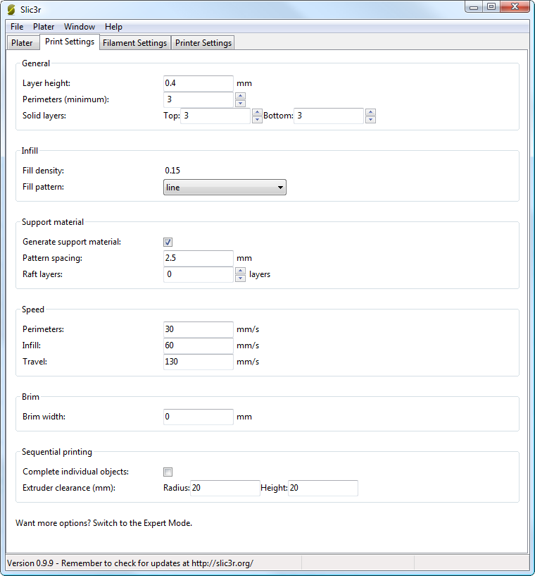
General
Layer height is the thickness of each layer, and it is the step along the vertical axis taken before extruding a new layer atop the previous one. There are several factors that influence how high each layer should be:
Perimeters defines the minimum number of vertical shells (i.e. walls) a print will have. Unless the model requires single width walls it is generally recommended to have a minimum of two perimeters as this gives some insurance that if a section of the perimeter is not printed correctly then the second perimeter will help cover it.
The upper and lowermost layers that sandwich the model are filled with a Solid layers pattern. For the bottom layers the important factor to consider is how the surface will look should there be a mistake whilst laying down the first layer, and for this reason it is recommended to have at least two bottom layers.
A similar consideration is required for the top layers. Because the intermediate layers are likely to be filled with a pattern set less than 100% then the covering layers will have to bridge this pattern and this can require more than one pass to cover completely.
Tip: It is sometimes worth considering altering the orientation of the model in order to possibly reduce overhangs. Another tip to consider: Setting the top solid layer to zero, and setting the infill also to zero, will result in a hollow receptacle, ideal for turning models into vases1 for example. Here manipulating the settings within Slic3r can be used to generate different kinds of prints, and not only be used to control surface accuracy.
Infill
Fill density is defined on a scale of between 0 and 1, where 1 is 100% and 0.4 would be 40%. For the majority of cases it makes no sense to 100% fill the model with plastic, this would be a waste of material and take a long time. Instead, most models can be filled with less material which is then sandwiched between layers filled at 100% (see Solid layers above)
A density value of 0.4 is enough to give almost all models good mechanical strength. A value of 0.2 is usually the minimum required to support flat ceilings.
Slic3r offers several fill patterns which will be discussed in more depth in section - Infill Choices. Choosing a Fill pattern will depend on the kind of model, the desired structural strength, print speed, and personal taste. The more exotic fill methods are usually too slow and unnecessarily complex for most use cases, and so most of the time the infill pattern is either rectilinear, line, or honeycomb. Honeycomb gives the most strength but is slower than both rectilinear or line.
Support material
Printing a model from the bottom up, as with FDM, means that any significant overhangs will be printed in the air, and most likely droop or not print correctly. Choosing support material (Generate support material) will add additional structures around the model which will build up to then support the overhanging part. The Pattern spacing option determines how dense the support material is printed.
Raft layers will add additional layers underneath the model and stems from the early days of 3D printing. It can help with prints without a heated bed, or where the bed is not very flat, but it is usually not required and is not recommended. The raft also requires post-processing to remove it.
Speed
In simple mode there are only three speed settings to consider:
- Perimeters - The outline of the model may benefit from being printed slightly slower so that the outside skin of the print has fewer blemishes.
- Infill - As the infill is hidden this can be extruded a little faster. Take care though not to go too fast as higher speeds results in thinner extrusions, and this may affect how the extrusions bond.
- Travel - The jump between the end of one extrusion and the next should usually be performed as quickly as the printer will allow in order to minimise any mess caused by material oozing from the nozzle.
Brim
Brim width is used to add more perimeters to the first layer, as a base flange, in order to provide more surface area for the print to stick to the bed with in order to reduce warping. The brim is then cut away once the print is finished and removed from the bed.
Sequential Printing
This feature allows to compose a plate of objects but have the printer complete each one individually before going back to Z = 0 and starting with the next one. See the section about Sequential Printing in the Advanced Topics chapter.
Filament Settings
These settings will normally be used infrequently, for example on receipt of a new roll of filament.
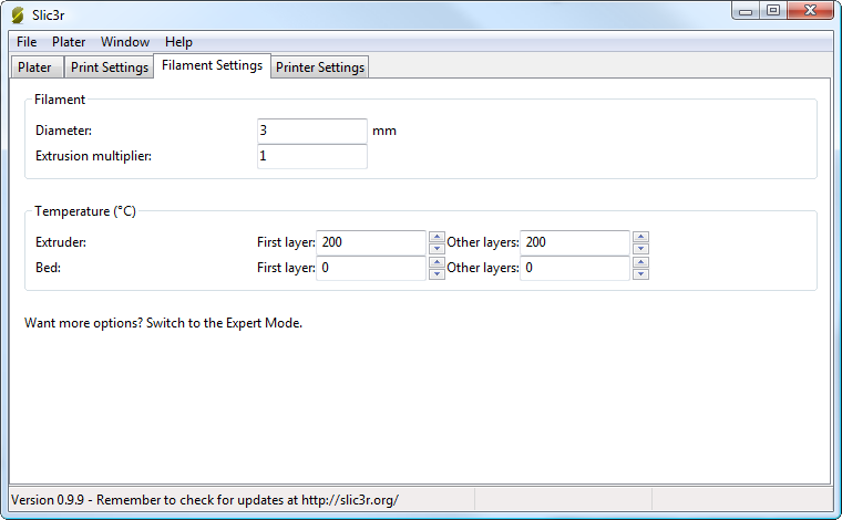
Filament
The Diameter setting will already have been filled from the value given during the wizard (see p.), but can be updated here. The Extrusion multiplier setting allows the fine tuning of the extrusion flow rate, and is is given as a factor, e.g. 1 means 100%, 1.5 would mean 150%. Whilst the value should ideally be set in the firmware it can be useful to test slight changes to the rate by altering this value. It varies the amount of plastic proportionally and should be changed in very small steps (e.g. +/- 0.05) as the effects are very visible.
Temperature
These values are also filled from the wizard, but here the opportunity exists to set the temperature for the first layer.
Printer Settings
These settings will be updated the least, unless Slic3r is going to be used for many printers, for example, in a 3D printer farm.
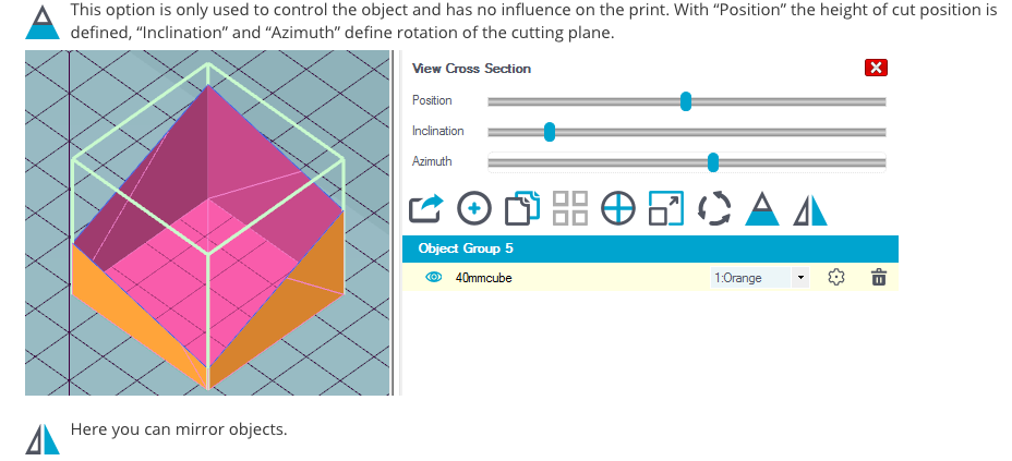
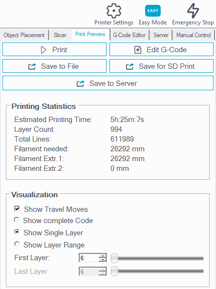
After slicing you can see the slicing result. You can rotate and inspect the whole model, a layer range or just single layers and you can visualize the travel moves.
3D Scanning an Object
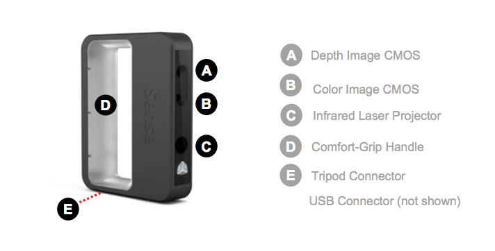
Sense
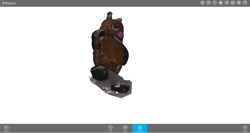
I used the Sense 3D scanner. Sense 3D Scanner gives users the ability to observe a scene in three dimensions and then translates the observations into multiple depth images. It then takes combines those depth frames into a 3D model made up of thousands of connected triangles, called a mesh. I created several set-ups to scan the object from all sides. I wanted to compare the outcomes of scanning the object positioned horizontally and vertically.
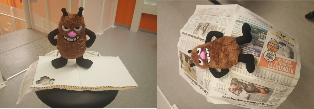
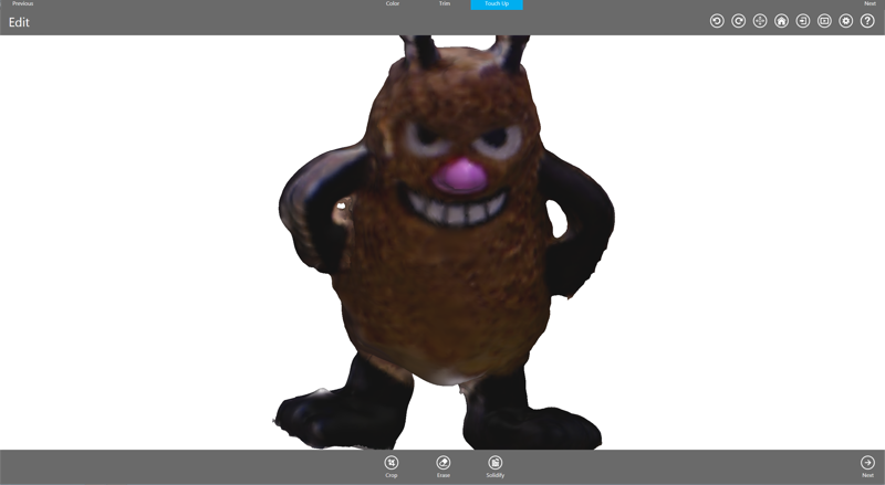
The outcome of the vertical positioning was significantly better since with the horizontal one back side of the object was not being scanned properly. With the vertical scanning, I had to close just a few minor holes with the Solidify Tool and get rid of some extra surface with the Erase Tool in the Sense's software.
For the future reference, I documented the detailed process of 3D scanning with the Sense scanner. The documentation is based on the scanners user guides available on the manufacturer's website.
Safety guidelines
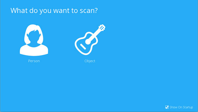
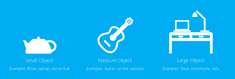
- Choose what you would like to scan. If scanning a person, you have a choice of scanning the person’s head or their full body. Click Person and select your choice. If you want to scan an object, click on the Object and choose the appropriate size for your object to begin your scan.
- Small objects: less than 16”
- Medium object: less than 40”
- Large objects: less than 80”
- Click on Start Scan, a countdown of approximately 3 seconds will begin to allow you to get in place to start your scan.
- Hold the scanner approximately 15” away from your subject and ensure that the image is placed center on your software screen.
- Slowly and steadily, move the scanner around the subject while viewing the image on the screen. Keep in mind, the image must be center on the software screen. If you would like to pause the scan, click on the Scan/Pause button. Click again, to resume the scan. Once you are satisfied, click Next to process your scan.

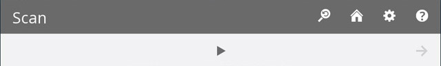
Scan Tool Bar: The tool bar located at the top of the screen provides options to set your Settings for the current scan, Home lets you return the view to the initial position or Start Over, delete the scan so that you can start the it over.
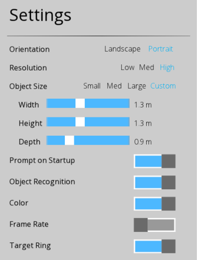
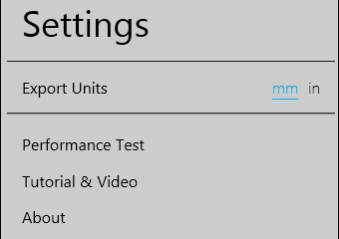
Scan Settings
Edit Tools
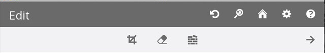
Crop Tool
Once the scan is completed, clicking Next will take you to the Crop screen. If you need to crop your scan, use the cursor to drag a window around the part of the scan that you wish to keep. When you are finished, click on the Crop button to remove the part of the scan that you wanted to delete. If an error occurred while cropping, simply click Undo (arrow button) and your scan will return to its original state. Click Next to go to the Edit screen.
Erase/Solidify Tools
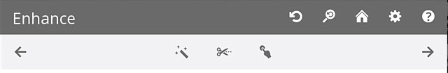
Enhance Tools
Share Tool
Click on Save to save your scan to your computer; you can save it as a stl., ply or an obj. These file formats will work on any 3D modeling printer. If you have a 3D printer available on your network, you can choose your printer and open your saved file in the printer’s client software.
ReMake
Autodesk learning resources including the Getting Started Guide offer tips on how to take photos for achiving best results. I tried accounting for the given advice (primarily using clear pictures, having sufficient lighting), but it was not simple to recreate perfect conditions.
I made 4 attempts to construct an object in ReMake. None resulted into an overwheling success, but there had been a visible improvement from attempt 1 to attempt 4.
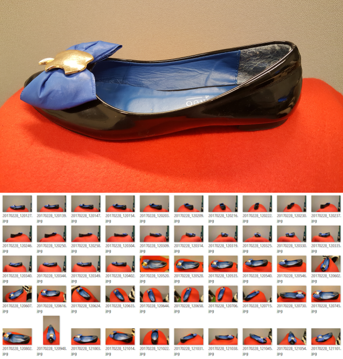 Most successful set-up with photos
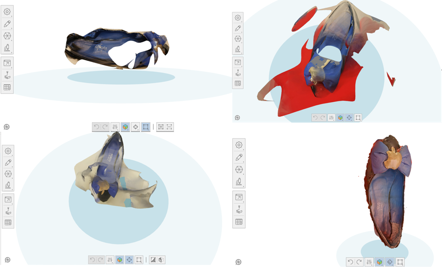 Fourth is a charm compared to the previous three...
I used Create a photo-to-mesh project and Create model Online.
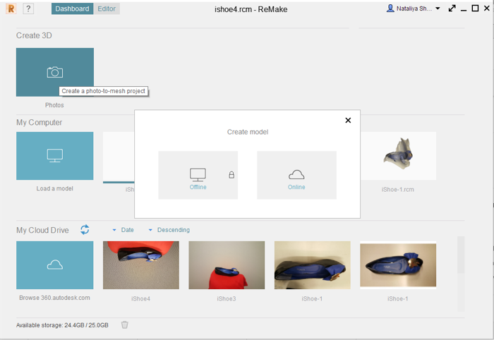
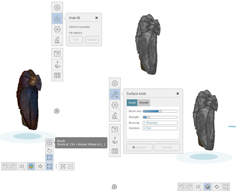
After selecting photos from Local Drive, they were uploaded to the Autodesk Cloud Drive, where the models were generated. In order to improve models generated by ReMake, I used available Editing Tools, mainly Brush Selection to choose modificaiton areas, Fill holes, and Surface Tools to improve the generated model.
Overall, for me the 3D scanner ended up working better than using ReMake. I got a more accurate mesh and spent less time with the Sense scanner. However, if I had time to practice more taking pictures and setting up background for meshing in ReMake, I think I would be able to get much better and more precise results in ReMake.
Advantages and Disadvantages of the Processes
 |
 |
|
| 3D Printing | Customizing objects, Fast prototyping of new designs, Low production cost |
Limited size of the objects, Raw material limitation, Production of unnecessary objects, Violation of Copyrights |
|---|---|---|
| 3D Scanning | Easy to use, Quickly capture many physical measurements of physical objects, Versatile application |
Expensive, Image clarity may be low, Complex internal geometry of objects cannot be visualized |
Important advantage of 3D printing is customization, because it allows anyone to print any design they want. This also gives a green light to rapid prototyping, fabricating a scale model of a physical part. With this new product ideas and solutions can be tested much faster than with traditional manufacturing. The designs can also be much more versatile compared to the traditional standard machining, which uses pre-maded molds and therefore restricts manufacturing possibilities. Overall, 3D printing greatly facilitates innovation.
Despite the advantages of 3D printing, it is always good to assess if 3D printing is the best option to create an object. Sometimes similar results with less expenses can be obtained by laser-cutting, molding/casting, or making composites. It is also likely that counterfighting can be easier and more difficult to detect with 3D printing. As of now, number possible materials which can be used for 3D printing is limited, it is constantly increasing, so this disadvantage is easily eliminated. Additionally, currently there is a limit to the size of the objects which can be 3D printed, with technological improvements this disadvantage is being eliminated.
When working on the assignment this week, I was able to see how 3D printing enables manufacturing designs which cannot be made subtractively. 3D printing process involves additive manufacturing or creating a three-dimensional objects by stacking layers of material under computer control. I also learned that optimizing te proess of 3D printing designs my be possibly by slicing and position objects in such a way that it requires minimum support structures and support material.
In general, 3D Scanning has a versatile use. I thought that the obtained scans can be useful only for recreating already exisiting objects (or people) as they are. However, researching some resources online (for example Almost Everything You Always Wanted to Know About 3D Scanning* (*But Were Afraid to Ask) by Direct Dimensions), I learned that 3D scans of objects can also be used to
- to make 3D models for animations or visualizations
- to make design changes to create a new product
- for archival purposes - to accurately record the state or form of an object to digitally repair damage that has been done to an object which can then reproduce that object in its proper form using rapid prototyping and milling technologies
- to perform dimensional and comparative analysis of an object, even FEA and CFD analyses.
- Finite element analysis (FEA) is a computerized method for predicting how a product reacts to real-world forces, vibration, heat, fluid flow, and other physical effects. It shows whether a product will break, wear out, or work the way it was designed
- Computational fluid dynamics analysis (CFD) is a method that uses numerical analysis and data structures to solve and analyze problems that involve fluid mechanics and fluid flows
From my experience with the assignments, 3D scanning is much easier and much less time consuming comparing to using ReMake. The object I was scannig came out quite well, I just had to do minor fixes to solidify the object. With ReMake, it took several hours more to take the pictures and process them just to get a digital model of the object, which afterward still needed to be edited further adding even more time to the oveall process. A major disadvantage of 3D scanning in my experience was that the scanner kept loosing tracking in the process of scanning. The other students in our lab had similar experince the same experience with the 3D scanner. Everyone agreed that it is much faster and easier to use. When doing his assignment, Eino noticed that if the object contains elements which reflect light (he was scanning a camera), this can impact the quality of the scan. A similar observation was made by Ivan, who appreciated the time it was possible to save with 3D scanning, but he noted a significant difference in quality of scanning between using 3D sense and ReMake. He managed to get a very detailed replica of the radio with ReMake. Also other students noted that the scanner missed details of the surfaces of their scanned objects. It was not an issue for me because my object had a rather smooth surface without small details.
Files in repo & external:
3D design Fusion 360 .f3D file + .stl of the two objects, reduced 2 Sense scanner .stl files, reduced Shoe scan ReMake .stl file (repo), original 2 Sense scanner .obj files, Shoe scan ReMake .rcm file (external)
Remember, remember...
- Even though 3D scanners and printers may not seem like hazardous devices, it is necessary to be familiar with the safety instructions
- To have a successful 3D printing outcome, designing a piece needs to be considered a part of the whole 3D printing process.
- Although with the 3D printing enables printing designs that cannot be made subtractively, major 3D printing limitations include small size of the objects, time and cost of printing.
- 3D sense scanner is easy and fast to use, however, it tends to lose tracking of the object which often means the process of scanning has to be restarted.
- To get a hight quality 3D mash with ReMake, proper photos need to be taken. The photos need to cover every single aspect of that object, must be sharp throughout the entire photo, have good overlap between them, and be under diffuse light (no strong contrast or shadows, thus absolutely no use of flash).