Assignment 5

3D scanning and printing
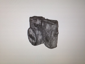
Assignment was 3D scanning and afterwards 3D printing it. I decided to scan my camera and then print it in a smaller scale. I made part which cannot made subtractively as a part of assignment 3 so now I concentrate to 3D scanning and printing scanned part.
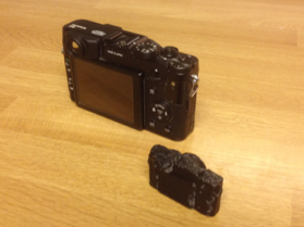
First I loaded Autodesk 123D Catch to my phone and it have quite good instructions how to 3D scan object. I placed news papers on the table and then camera on the papers. Papers help software to recognize which way photos are taken. Software needs 24 photos from different angles to make 3D model.
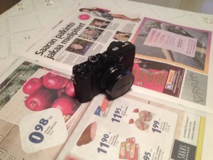
Camera on the table
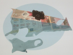
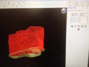
3D Model in software
Conclusions
Using 123D Catch was easy but finishing model was slow tools in Remake weren´t as good as they could be. Also my model was difficult because it have small details and back screen which have mirror effect when 3D scanning it. Thats why it take much time to finish it with surface tool.
My opinion is that 3D scanning software 123D Catch suits to simple big models with no small details to scan. Also bright mirroring elements on model will cause problems and more time needing finishing in Remake software.
Secondly after making model I loaded it to my computer from 123D Catch web application. For finishing model I loaded Autodesk Remake software to my computer. I Open mesh.obj model file with Remake and I cleaned and finished model.
I selected extra particles like news papers with lasso tool and then delete them with delete tool (Edit -> Delete).
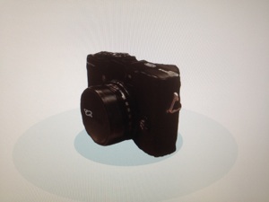
Cleaned 3D model in visualisation view
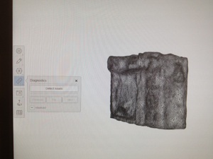
Cleaned 3D model in mesh mode
After cleaning extra particles I run Diagnose tool (Analyse -> Diagnostics) which check the model and warning from flaws on model. Tool can remove loose particles if there is some, fill holes and fix intersection problems if it find them from model. After fixing faults and checking that model is free from warnings I finished and smoothened edges with Surface tool (Edit -> Surface tool). With Surface tool I smoothened edges and cameras back screen by pulling and pushing model mesh.
When I was happy with my model I just scale it down little bit.
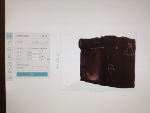

I go to Model settings and choose Scale & Units. Set units to mm and choose scale by value. Then I set height of the model to 30 mm so other measurements became length 43,7 mm and thickness 38,3 mm.
At the end of modeling I Export (Export -> Export model) my model to STL file for printing. I use Tinkercad STL and high quality as a Export settings.
PRINTING
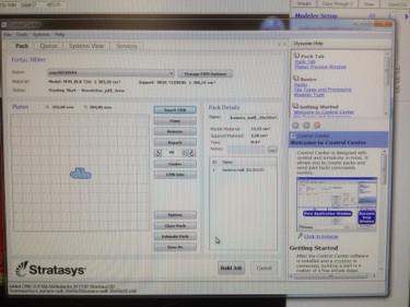
I used our FabLab Stratasys Fortus 380mc printer for printing. I opened STL model in Insight software and made slicing by using fast slicing tool (green flag). I used ABS material and used settings Part interior style: Sparse , Visible surface style: Normal, Support: Smart. I transfer sliced model to printer by using printer control center software where I can multiply model and rotate it if I need to.
Running diagnostics to the model
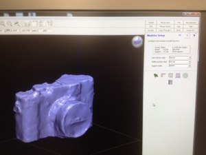
Model in Insight software
Sliced model in Insight
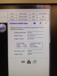
Estimated priting time and amount of material
Sending printing file from control center to printer
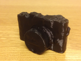
Printed model and original camera front and behind
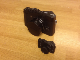
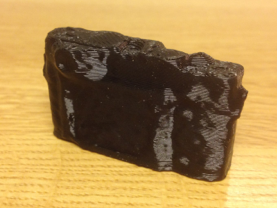
Close up picture of printed model
Group task
As a group work (Mikko, Jari and Yrjö) we need to test design rules of printing so our group printed test parts and then measure dimensions. Test parts were printed on different printers our lab Leap Frog printer, Formlabs Form2 SLA printer and Mikko Toivonen´s selfmade printer.
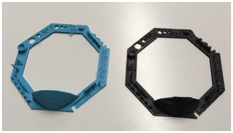
Test parts. Blue made with Leap Frog and black Mikko´s printer.
Generally it was clearly seen that small dimension shapes (<0.5 mm) are really difficult to produce with printers at these accurate levels. Also Shapes with accurate dimensions (tolerance +-1mm) are difficult to make these printers because difference in dimensions when compared to design dimensions depends on shape total dimension. Printing letters or numbers can be on some level but I do not recommend to trying write text at least small letters with printer. Also thin axels or towers can be made but shape is not accurate and breakage possibility of element during printing is quite high.
From our group test parts can be seen that also differences between printers are noticeable and dimension accuracy depends on printer or printer type. So I would say that our lab (tested) printers design rules are:
-
-Do not make small (<1mm) shapes
-
-Engrave small letters or numbers with laser afterwards (do not print)
big letters can be printed
-
-Design always shapes the way that there are material for finishing shape by hand
if shape is accurate or critical for assembly
-
-Slice part in that way that a very few or none supports are needed in print
-
-Make wide long parts avoid prints with lot of height
Only 3D printable part
There is also a task to design and print part that is not possibly to make ordinary subtractive methods. Like you see below the switch level chamber is totally closed so it is impossible to product by material decreasing methods.
Formlabs Form2 made best surface quality print with 0,05 mm layer thickness. Mikko´s printer made better quality than Leapfrog when estimating parts by eye. All printer reproduced parts in good quality when considering that parts made by 3D printer.
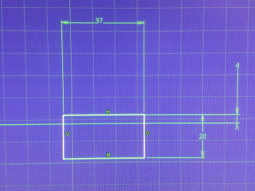
Basic sketch
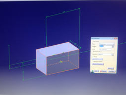
Extruded part
Pocket made by pocket tool
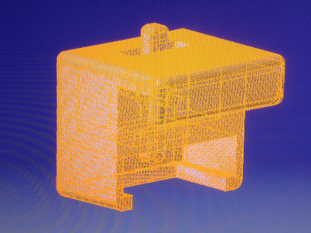
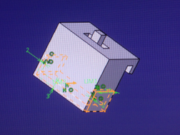
Final Design with STL mesh
I designed on/off switch which again part to my final project. With enclosed design it gives little better protection again elements than just plain on/off switch. My switch is based on idea that switch mechanism is enclosed and part of body gives shield to plain on/off switch which attached to my switch body.
First I draw basic rectangle sketch and have idea to add and remove parts to it to get final shape what I wanted. Secondly I made pocket inside of first extrusion to make space to switch level then I make attachment hook for plain on/off -switch and hook for attaching whole switch to my camera rail. At last I added switch level and use 0,2 mm clearance to make switch work after washing our printer soluble support in washer bath. Size of plain on/off -switch I measured from one one/off -switch found in our FabLab.
In Catia modeling tools that I used were basically rectangle and extrude. In sketch mode (select 2D plane and click sketch) with rectangle tool you can draw rectangle and change its dimensions by clicking dimension number. After drawing a rectangle change sketch mode to 3D mode and use extrude tool by selecting geometry (rectangle) and clicking extrude. Then change desired extrusion amount and you get rectangle size and extrusion thick box (1 & 2 picture below).
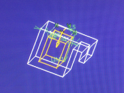
Switch holder pocket made by pocket tool
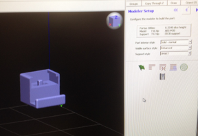
Opened STL file in Insight
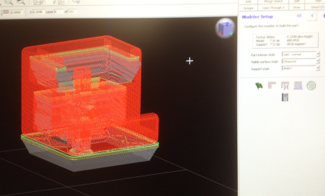
Sliced STL file in Insight
Final printed on/off switch
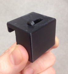
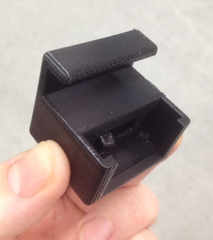
Final printed on/off switch