Electronics Production

This week my top fear was soldering, as my previous experience was not the best. I usually solder making not so much clean joins. Many times I made a mess and several jumpers got joined so afterworks I have to clean a lot. Still I have to learn and practice more as my precision is not the best.
Lesson
Academany Fab-2016.02.17D Lesson 04: Electronics Production from Fab Academy on Vimeo.
Academany Fab-2016.02.24B Review 04: Electronics Production from Fab Academy on Vimeo.
Milling the Board (PCB)
The machine at FabLab Leon is a Modela MX-20, is a machine shared with many other fablabs in the world and is compatible with FabModules.
We can watch and useful video for the Modela by Adam Harris
The board is made of cellulose and not of bakelite, usually know as FR1 model. This material allow us a perfect balance between durability for our products, even it will stands less than others types of materials, but is softer. So the rotatory cutters of the milling machine will suffer less and allow us that with one milling bit we can made around 20 PCB (Printed Circuit Board).
We have to be careful with the material of the PCB, fiberglass boards are dangerous for milling in a FabLab environment as the dust produced when are milled, are so small and sharp that get so much floating in the air. Being so small can be easily inhaled and pass to the deep of the lungs.
The PCB is a variant of s a 100% fab-able version of the usbtiny programmer from simpleavr , in this case the fabtynystar, that is a evolution of the previous David Mellis' FabISP and Andy Bardagjy's FabISPKey.
Fab Modules
The Modela allows to be controlled by Fab Modules. now the most newest version is the HTML5. I’m lucky as FabLab León had a nice workflow so I haven’t to install them. even I fight with them at one macbook. I you need to install them, in the Github page of the Fab Modules there is a Tutorial
Preparing the Modela - MX-20
As is this is a precision work, you have to be sure that the board is as much stable and horizontal as possible.
So if we start a new pcb material sheet, we have to clean the dust underneath. A machine clean is a machine with less chances of imperfections and problems.
With a ruler take note of where you want to start milling and focus the 0.0 of the work.
As a sacrificial layer of material is essential for protecting the the malling when is cutting or we make an error with Z axis coordinates.
We fasten with a special double tape the PCB board to the sacrificial layer, and this layer we fasten to the machine. Checking again to be placed as much horizontal as posible.
Set the correct milling bit in. As to about vibrations and that the PCB moves, always milling should be done before cutting. So we choose 1/64”. Carefully we take the bit and with an allen key we fasten it. We don’t have to press hard as it can be over tighten. The machine has to bolts.
Move the machine to the zero point pressing VIEW button.
Pressing the DOWN button of the machine will lower the Z axis. Take an example of the thickness of the board plus the sacrificial layer. You can put it in the upper part of the machine and use it as cap to down it lower than it. Around 3-5mm more will be enough.
If you have move the machine with the Fab Modules and you are up the 0.0 starting point. Now you can lower the bit with the allen key so it sits on the board. Fasten it carefully. Slice with the help of the finger helps.
Zero point is an absolute position in the lower left corner. You need to play with the X and Y values to find where you want to start. Use the position you noted before.
If for some reason you need to reset the milling machine, say to clear its memory of a job it did not finish. Press and hold in both arrow keys at the same time. Pressing up and down to clear the cache of the machine only works in view-mode (light next to view button turned on)
Prepare the board files on the computer using FabModules
Download the board files. (Zaerc)
We need two files. One is the milling of the traces and paths of the circuit that will be down by the small bit end mill 1/64”. Another file is needed for the cutting as we need to change the end mill bit for a 1/32" end mill (flat). So it’ll be needed to change the bit bit.
Using the FabModules. the machine can be controlled and give it the paths for milling or cutting.
INPUT: We use one of the png of the board design.
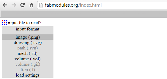
OUTPUT: In this case is the Roland MDX-20 (.rml)
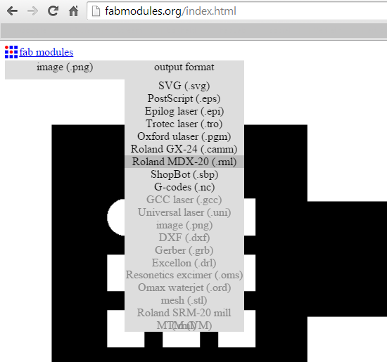
We introduce the data depending the board and where is our design. Usually selecting the end mill bit measure put recommended data.
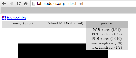
MAKE PATHS: To convert the PNG to paths for be milled by the machine after all the options we have chosen.
MOVE: This command will move the end mill bit to the coordinates we put. To check everything is correct
SEND: The job is sent to the machine and it will start to mill.
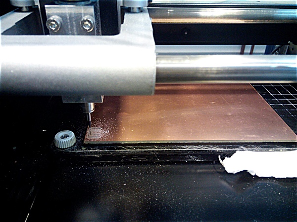
FabAcademy 2016 - Modela MDX starting milling FABISP from BjLanza on Vimeo.
After the milling of the paths we have to repeat the process to change the end mill bit and change the image for cutting.
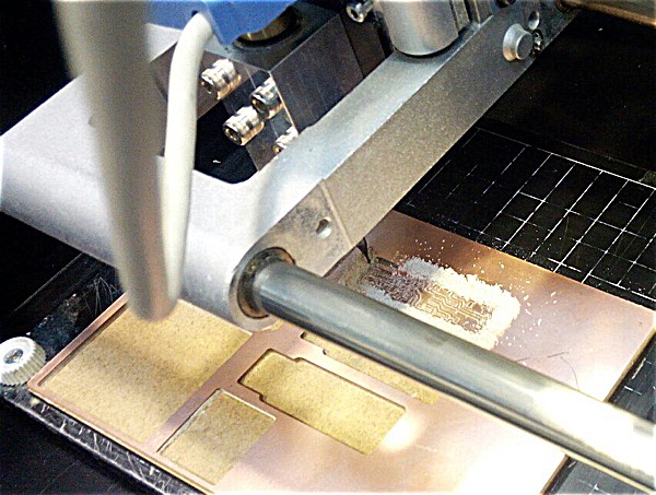
When the board/boards are finished we take out of the milling machine. clean the dust and clean all the debris of the board, with the fingers or using a tool to flatten and level the PCB.
Then we use Isopropyl alcohol to clean with a brush the board, dust and fat.
After that I could confront my Nemesis
Soldering
Even I had a great teacher in my guru instructor Nuria, that show me several tricks and gave me encouragement. I’m a little disappointed with the results. Maybe I’m a little perfectionist and I need practice and get better selfesteem.
After some practice with the solder I choose to make Zaerc model using the 5V version 0.3 (Bas), as was easy with an integrated circuit with less pins.
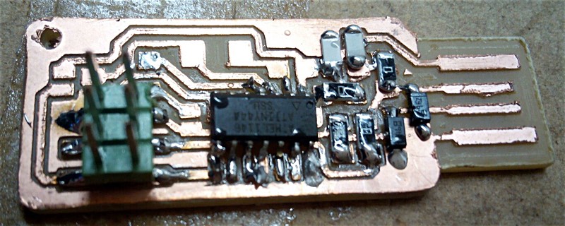
As I have the referenced of the previous one that Nuria soldered and the instructions it was not very complex.
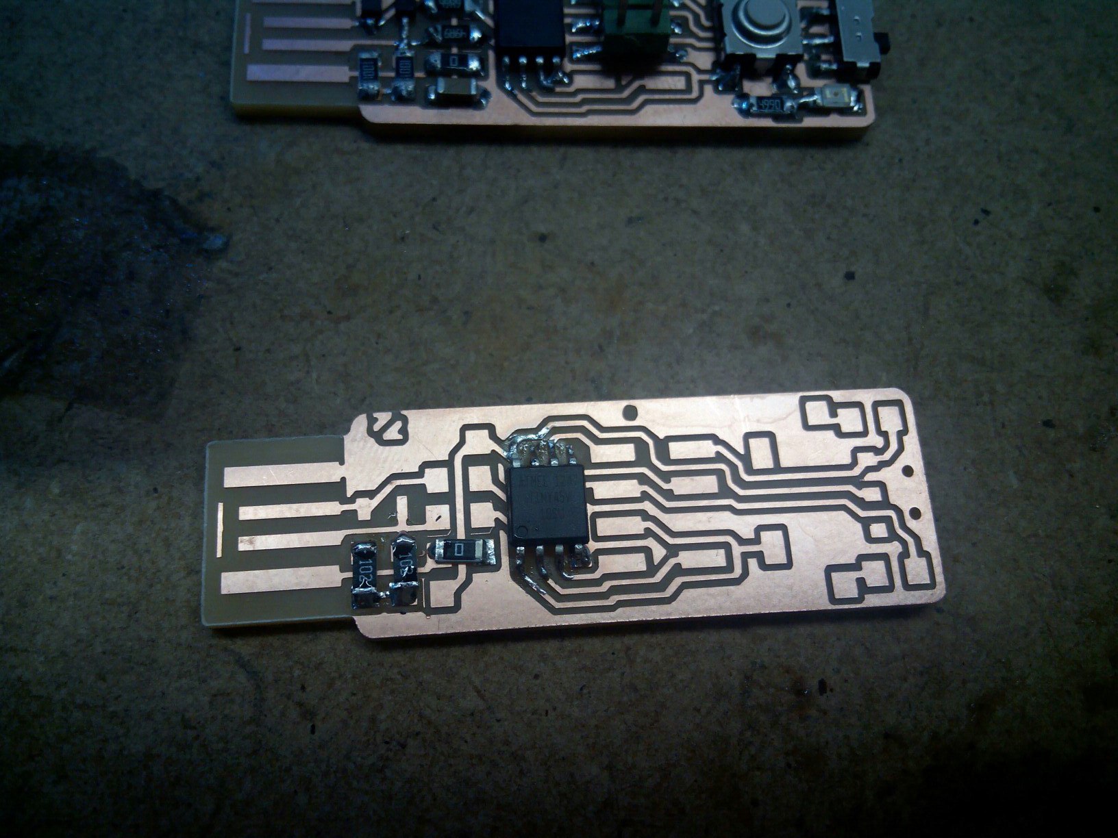
Also not was very complicated choose from the drawer of components are is very organized.
At least my soldering was good enough to do it at first without excessive mess.
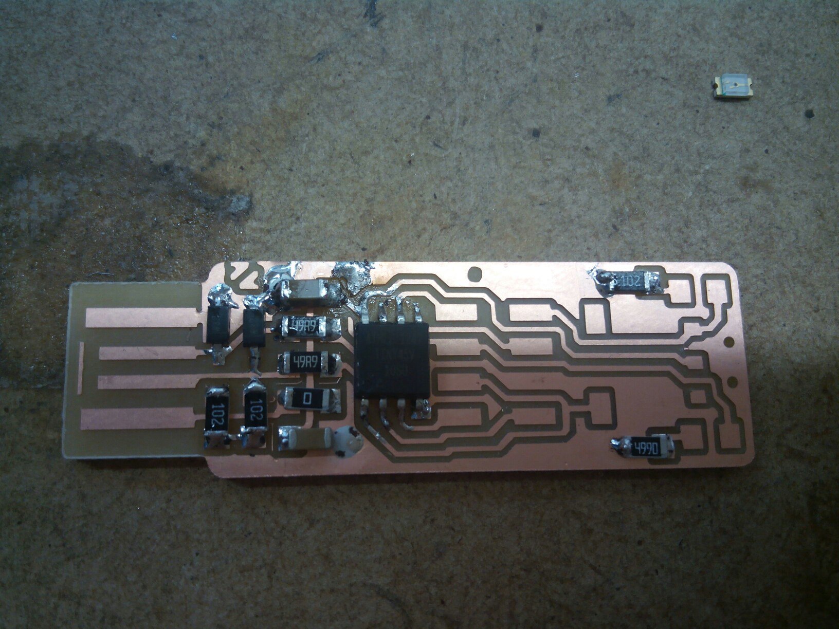
During the soldering or at least once after finish, we have to tester the connections to see the connectivity and that the current pass across the circuit without short-circuit.
When everything is ready we wash again the board with Isopropyl alcohol
Now we can proceed to program the board
Programming the board
Again I was very lucky as my instructor Nuria has done a great work preparing wonderful tutorials y being sure that It can be done. The downfall of this is that as aren't any problems I can't learn of them. But as I needed some time for learning soldering and prefer to don't get out a lot of my comfort zone while I got focused still in fix the problems I found in my workflow.
For programming the board on Mac OS X you need have installed Xcode environment and CrossPack
One advantage of the Zaerc model is that you don’t need as other boards to desolder some 0 resistances is everything by Software.
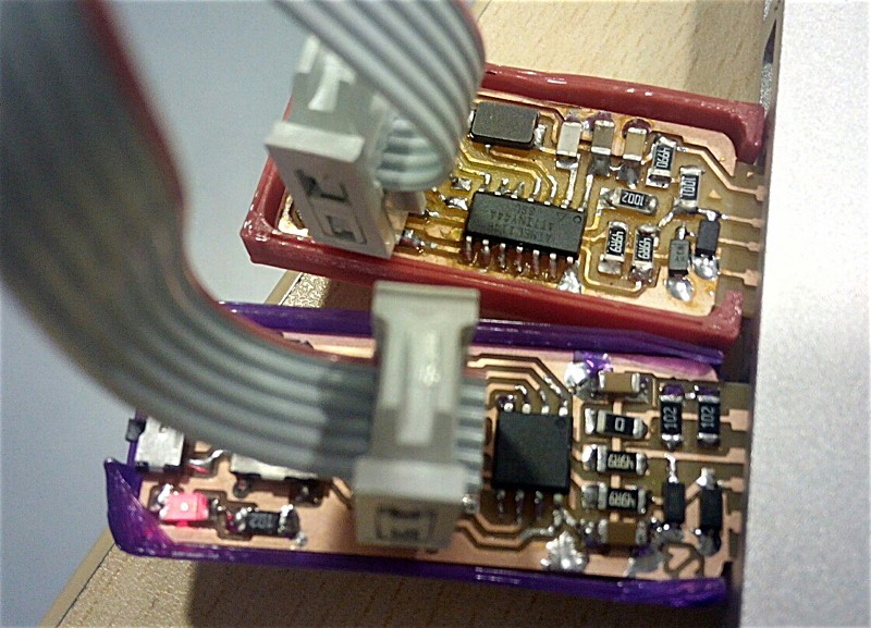
Connect the Fabstar and the Fabisp to the computers usb, and between them with the 6 ribbon cable.
Be sure that both connectors are paired at the same way. Usually red line or one color to the same side.
Power on the Fabstar with the switcher. The red led will light.
Download the firmware
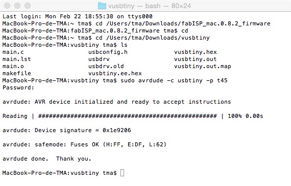
Open the terminal
Go to the directory where you have extracted the firmware
Type sudo avrdude -c usbtiny -p t45
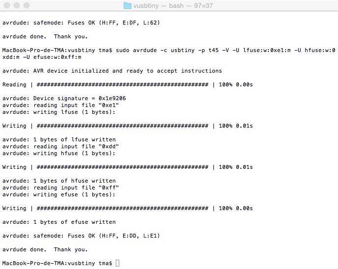
Program the fuses
Type sudo avrdude -c usbtiny -p t45 -V -U lfuse:w:0xe1:m -U hfuse:w:0xdd:m -U efuse:w:0xff:m
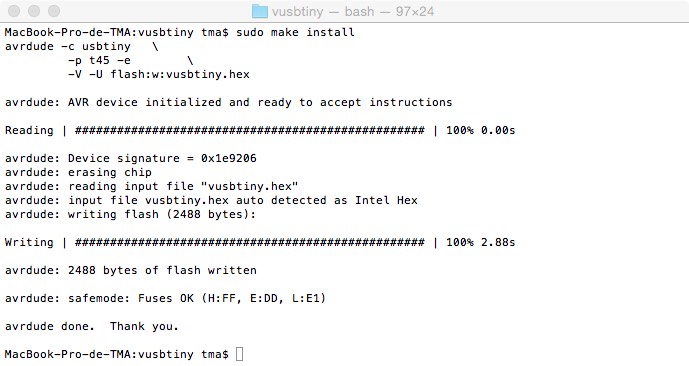
Install the firmware
Type in the directory where is the firmware vusbtiny tma$ sudo make install
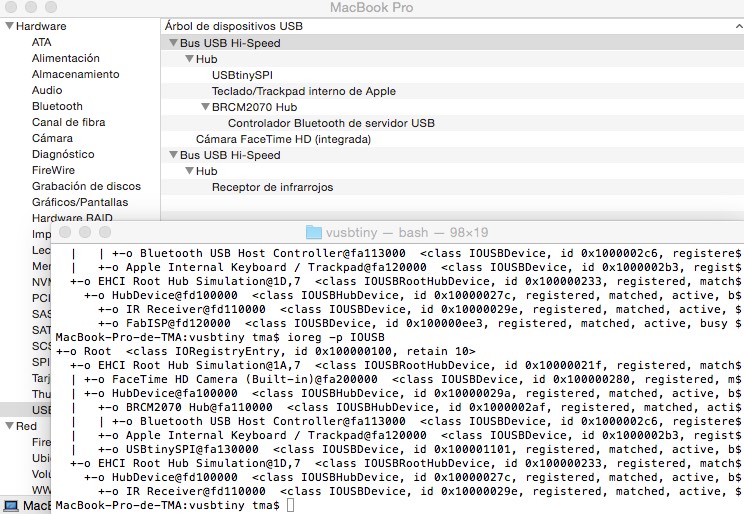
Check USBs
You can do it by system profile or typing in terminalvusbtiny tma$ ioreg -p IOUSB
Transform the board in a programmer
Attention this is an irreversible process!!!
Reconnect the original FABISP
Type sudo avrdude -c usbtiny -p t45 -V -U lfuse:w:0xe1:m -U hfuse:w:0x5d:m -U efuse:w:0xff:m
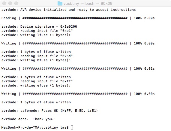
After this step, if you repeat the command it should give an error.
