Input Devices
This week has been another one where my expectations are still not fulfilled, because my little lack of some essential skills, in this case of electronics design, for making physical objects with unique ids.
Lesson
Here you can see the lesson of week 11 about input devices
Academany Fab-2016.04.13D Lesson 11: Input Devices from Fab Academy on Vimeo.
Review
Academany Fab-2016.04.20B Review 11: Input Devices from Fab Academy on Vimeo.
Research
Even with the great insights and advices of Neil, I try to get more info about how to make with LC circuits (capacitors and inductors with coil) physical objects that can be read by a sensor and trigger different events for my project of an interactive guide for fablabs.
Neil show us a video of a exposition about interactive furniture. In this video users could place a physical round token which have a LC circuit that was read by a reader in the tablet and different actions happens.
I started to research and this exposition were a common project of MIT Media and one of the authors is Neil. You can download and read the paper here
The system is described since page 5 and is very interesting as is an installation with more than 15 years, where some of the advances in digital fabrication where still in development, and Neil as always were pioneering them.
For me the most interesting part is this: The tag, shown in the foreground of Figure 9, is a simple LC (inductor-capacitor circuit) resonator built from a 3-inch diameter printed copper coil and a ceramic chip capacitor soldered onto the coil. Using the same coil size with a different capacitance for each coaster results in resonant frequencies ranging between 5.4 MHz and 13.2 MHz, in increments of 300 kHz.
Neil also has a very interesting paper about interaction with touch tags, the 2 paper documents can be download here
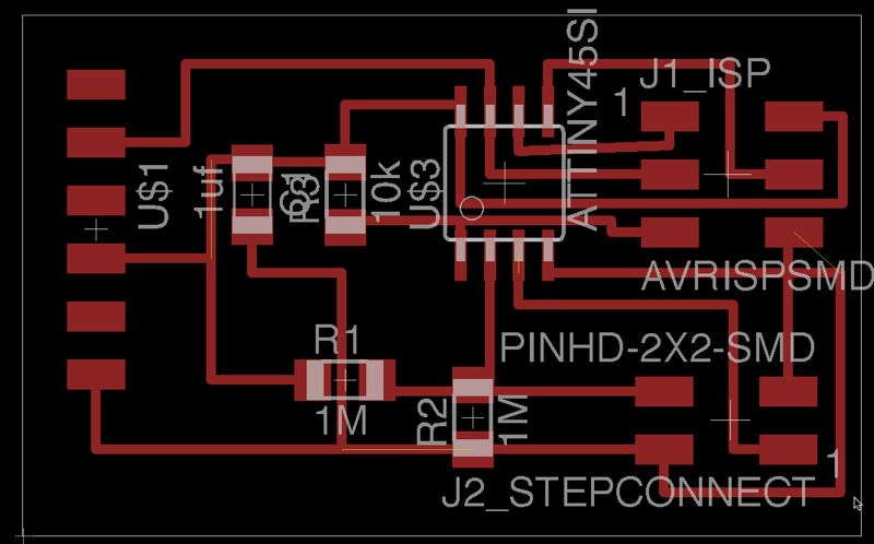
Designing the sensor board
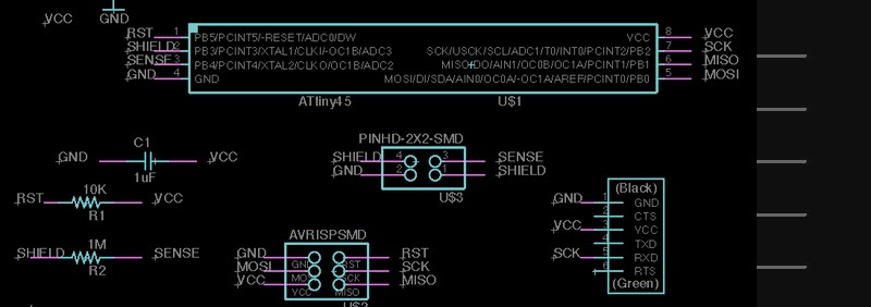
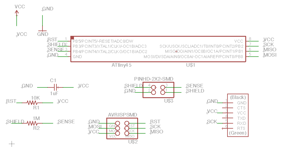
I just remade the basic sensor board made by Neil in Eagle. It took some time but It was done.
Also I made the design for a second board with more step sensors and Attiny 44 processor with bigger memory.
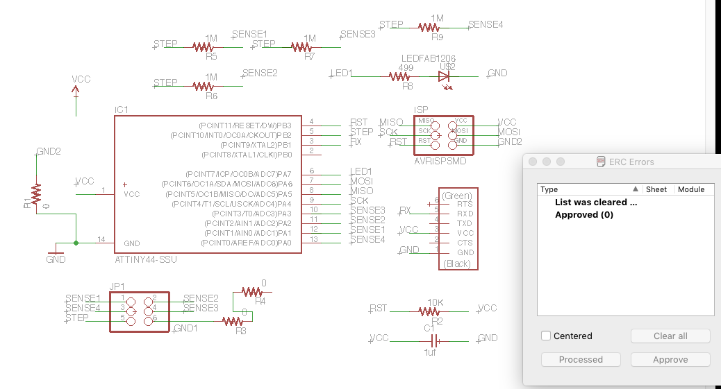
You have to be careful when using the autoroute feature as the board and schematic can be unlinked and you will have problems. Eagle have auto backup features and you just can rename the schematic to generate a new one.
Solving the problems
The autorute function and being newbie in a program, make me suffer a little, the good of Fabacademy and the drilling of make each week digital fabrication skill is that you learn, and you can came latter to these difficult blockades and find a solution.
The solution was not more memory or more pins to try avoid jams o rattraps, instead is better thinking, a better placement of the components and little tricks that is normal your learn with experience.
I return to a Attiny 45, that have enough memory and digital inputs as I only use a maximum of 3 capacitative steps inputs. I just put GND and VCC plus Input signal to the FTDI connection. Still ISP for programming the board, and better placement of resistances.
Also that tricks as pass between the middle of a resistance, use elements to jump other paths, makes that at least everything connects.
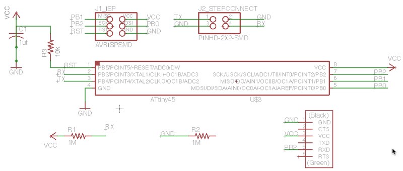
Also that tricks as pass between the middle of a resistance, use elements to jump other paths, makes that at least everything connects.
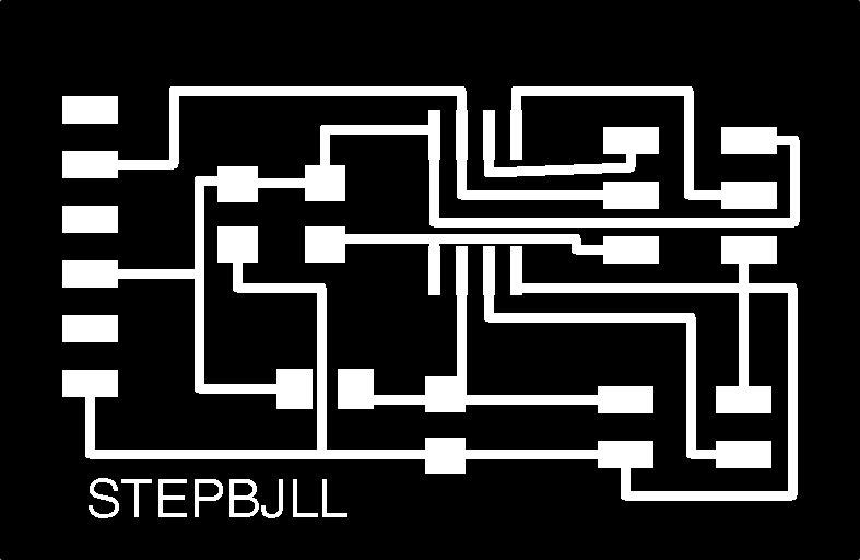
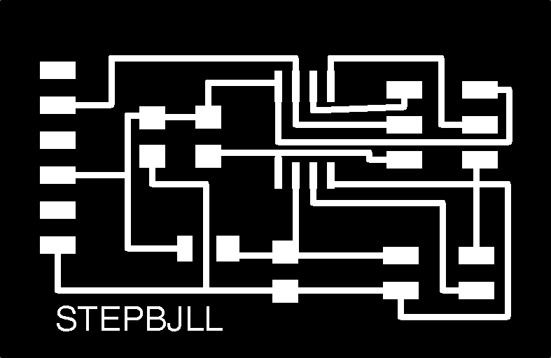
PNGs for milling in the Modela-MX20
Here you can see and download the 2 different pngs for milling the board. As if don't need holes, there are only 2 images.
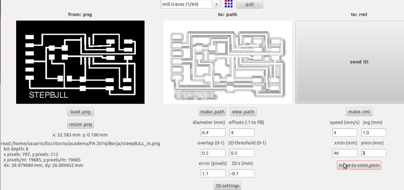
You would have to check for shortcircuits as many paths are very near, for example in the microcontroller as I have to enroute by the inside, So I won't trust this board for being fundamental saving the world.

In the fabmodules you can see that the paths in the microcontroller are not milled well.
You can see that the lower pins of the microncontroller are join together.
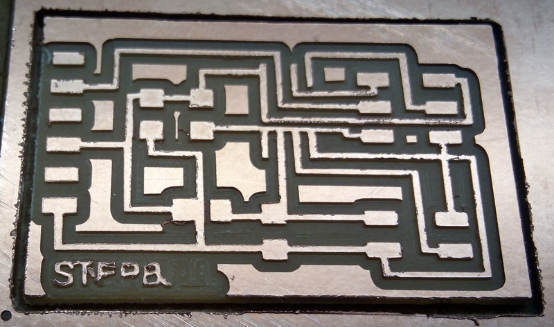
With a sharp cutter you can split the paths.
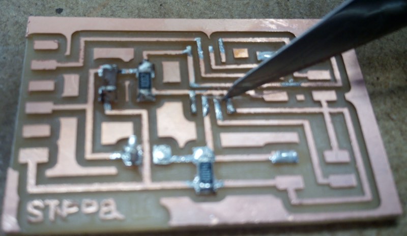
But it's much better modified by a image editor like Gimp and make the pads of the Attiny a little smaller making more space allowing the mill to enter and make a clean path.
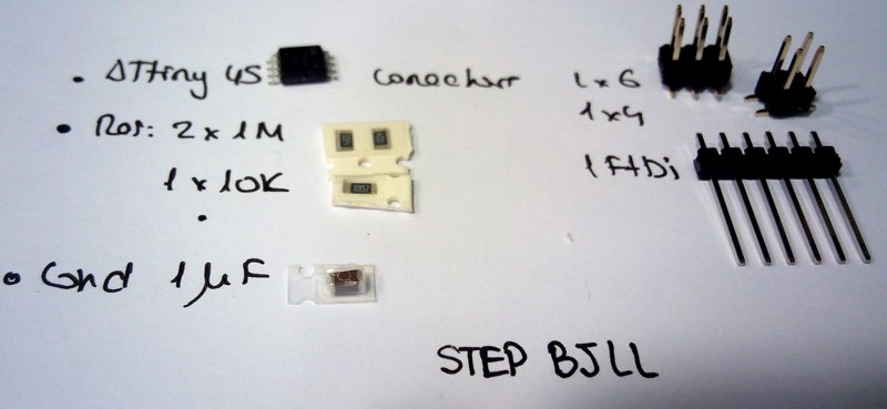
Here you can see the components of the board, that is simple one, with the Attiny, 3 resistances, 1 capacitor, and 3 pins rows.
Programming the sensor board
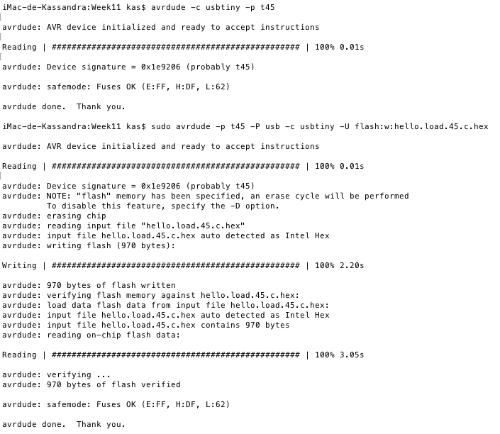
As I made lot of hard work in week 8 this worked like a charm. I checked that was a tiny45 and uploaded the .hex file. I'm proud that still my FabISP works fine. You have to check that the ISP is transmitting data with the led blanking.
I uploaded the example of Neil that can found in the weekly assignment. That can be download here.
Step Sensors
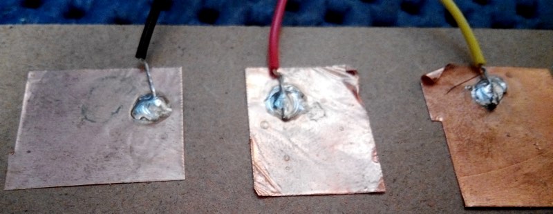
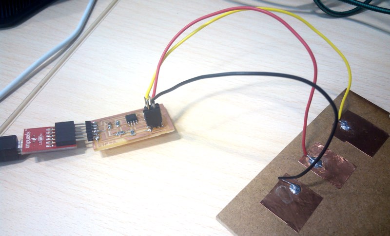
Sometimes the tinkering is the most easy thing, I just put lot of flux in some copper vinyl little pieces, and solder simple copper cables above a mdf leftover of a cutting job, and connect to the pins in the board.
The board connected to the FTDI and the sensors.
Video showing the sensor
Here you can see a short video of my desktop running the basic hello.load python script.
SVG Coils
I made a couple of coils design for cut them in the vinyl cutter if is possible with time.. I would need to study a little more the maths of this subject but is ahead if my knowledge at this point.
Update - Another sensor in the Project
After so much looking around as you see about a method to identify different objects in an unique way, Neil point us that we could use RFID/NFC readers that in this case connect to a modified Fabkit, you can read more here
