Output Devices

This week again soldering gave me some problems, as ATmega328 has 32 little pins that have to be soldered with so little space between pins, that tragedy was floating in the air. And of course I have to make joins between pins with my poor soldering skills.
Lesson
Academany Fab-2016.04.27D Lesson 13: Output Devices from Fab Academy on Vimeo.
Review
Academany Fab-2016.04.27D Lesson 13: Output Devices from Fab Academy on Vimeo.
FabKit milling
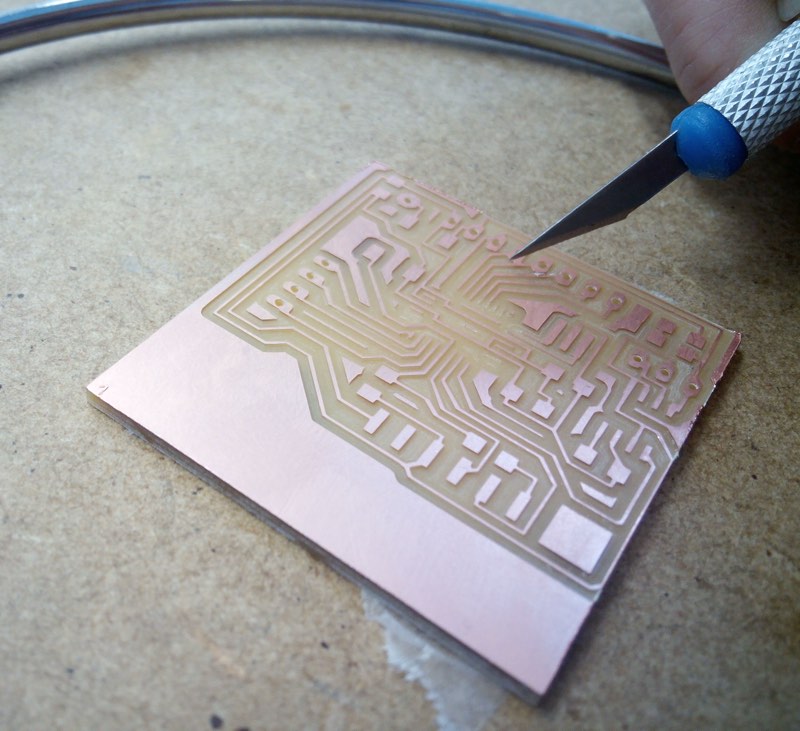
As any electronic themed assignment week, I have to use the Modela MX-20 for milling and cut the traces for the pcb boards, using the fabmodules and adjusting the Z for each different bit for the Modela
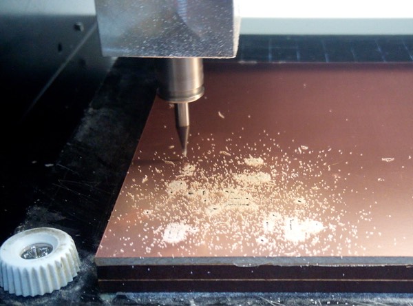
As I had so many problems with little Attiny microntrollers as they have less pins for use and I made a little mess with connections as I wanted to put ISP plus FTDI plus any other connections to inputs or outputs, I tried to design and mill a fabkit shield as I saw great results to my classmates of Madrid CEU
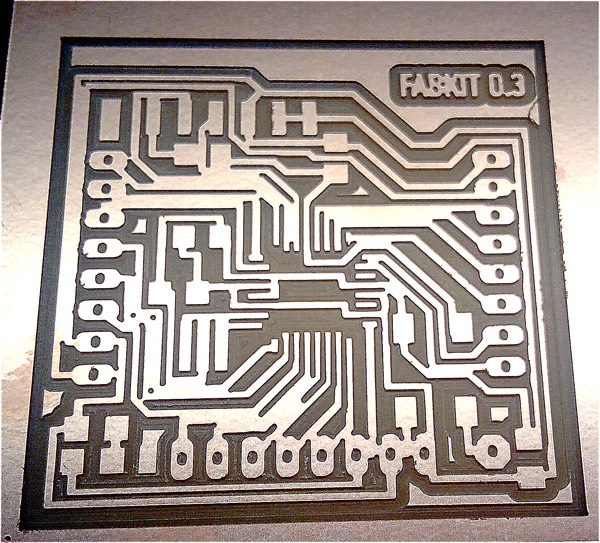
I choose a Fabkit v0.3 as I thought It would solver and improve some little designs of v0.2 but after cutting I saw that this design is not for Modela cutting with drilling bits and is aimed for plasma cutting.
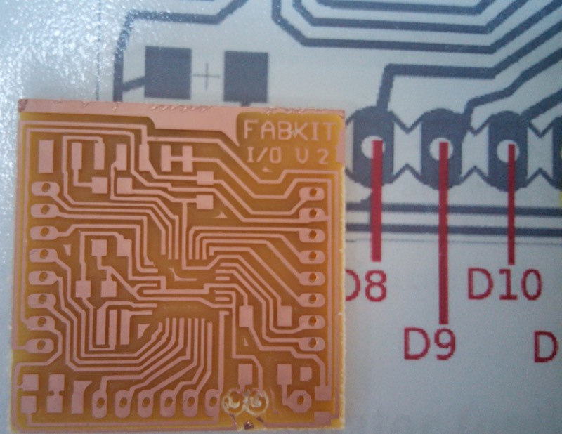
The v0.2 Fabkit is nice milling, but I have a problem as I trusted in the files that was in the server and I discovered that when milling the holes, the png have to be inverted, so as anyone can look closer 2 holes in the right bottom side that are GND and VCC where ruined
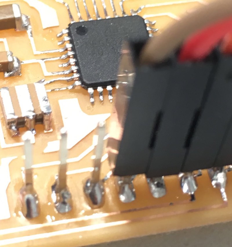
I discovered a little trick for soldering long pins like FTDI ones that are in the "air" and is using clay for fixing them in place, and I really found much easier to do it
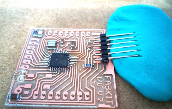
Any case even after soldering a little more components this first pcb board was sacrificed in the altar of knowledge and experience, making future brothers easier to make.
Programming board
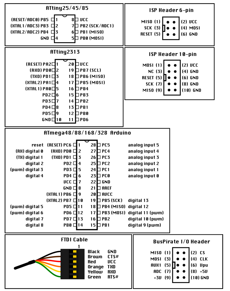
Fabkits don't have classic ISP 3x2 pins connector, that I use in previous ATtiny boards, for example the ones that are made as examples for Fabacademy, so you have to understand better where are the connections for burning the boatloader
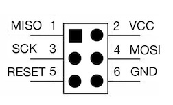
This cheat sheet is very useful to see where do you have to connect ISP in the different pins of different microntrollers. Even has a little diagram for Bus Pirate programmer, that is a very useful tool I bought thinking to program
RGB Led Strip Board
I tried to make a RGB Led Strip microcontroller board, mostly for use the Mosfet integrated components and understand how they work and how should be connected.
As many circuits use similar to Tip 120.
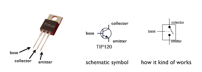
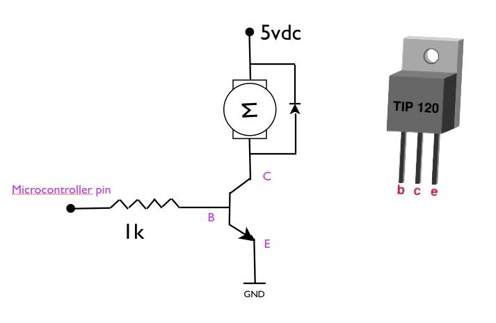
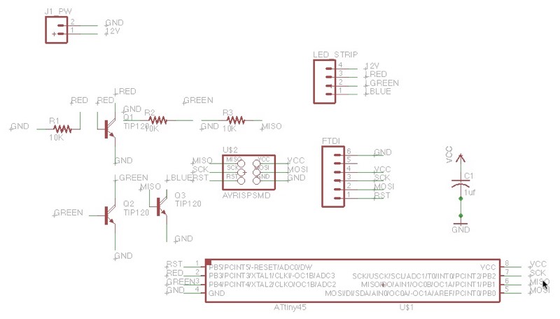
Again not many problems to understand the schematic and have everything well connected.
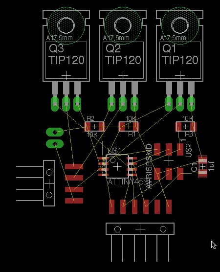
The problem is when I have to connect path that I usually get blocked and very frustrated
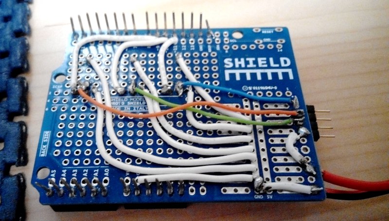
The frustration even grow further as I know is a very simple circuit, as I solder it in a not "fabable" style with protoboard and pinholes soldering.

Everything is more easy when you have top and bottom layers and you can jump over other paths as cables are isolated.
LED and DMX Shield for Fab Kit
Again another good example of how a student across the weeks of the FabAcademy can get a good progress and return to solve problems. In this case after all these end roads I just switch to shields for the Fabkits, that even configure in my needs.
This Shield has a DMX output the same as the Fabkit DMXduino that is described in next section and is an important part of the projects.
Also has the LED Strip circuit both for Normal and RGB, leds with an connection for external power source.
Apart has 3 pin connector for Neopixels that use GND, VCC and Data.
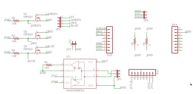
Lot of tricks and roundabouts to get all connected and that is the experience of learning. That is why I add this.
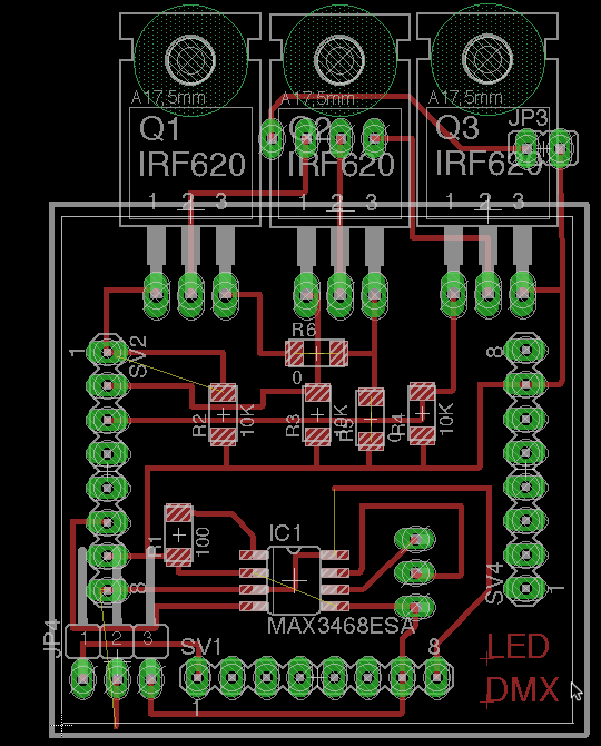
You can download the schematic and the board of the DMXShield.
I'm proud of the advance of ecad design, even is far of being perfect and still lot of learn and understand.
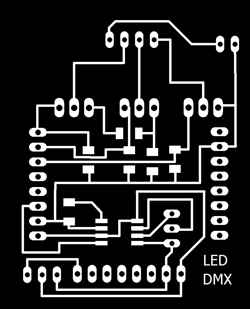


Even can be milled nice without problems. Still not tested but it seems that will work when I have time to finish it.
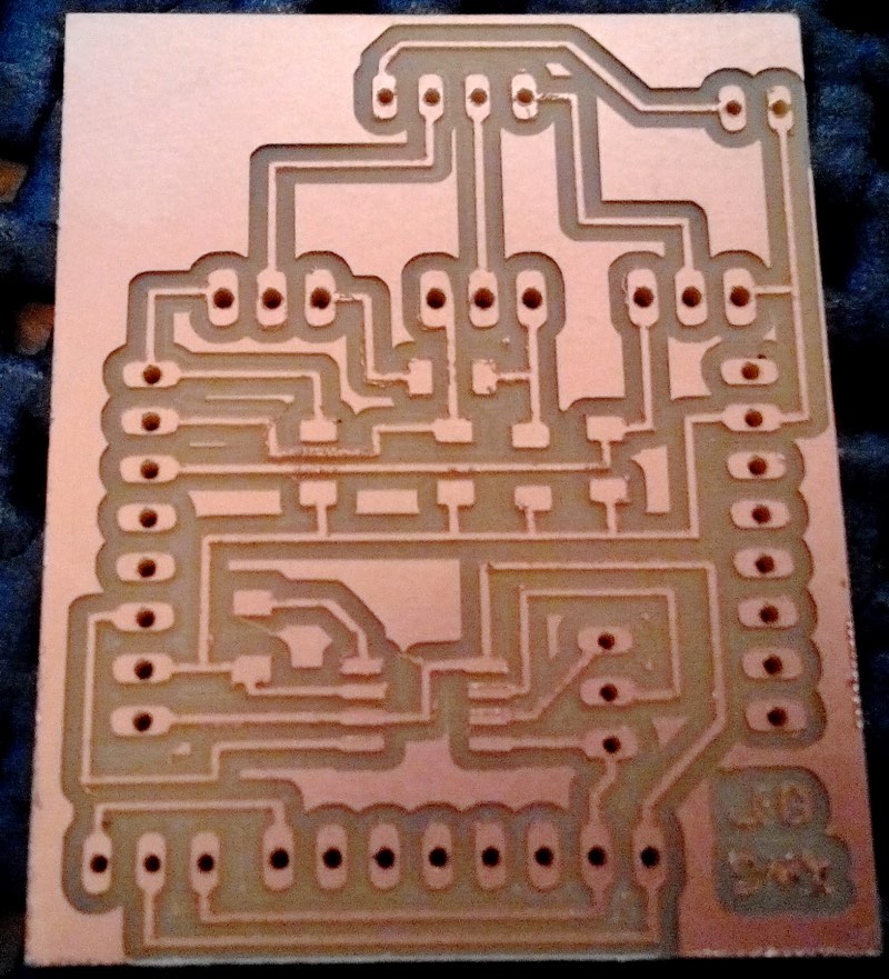
DMX board research
After some problems with this practice, I just learnt what I need and also from my mistakes and errors and modify a Fabkit with a dmx output. Is the same as used for the project and it's documentation I included here.
DMXduino
This is a wonderful example that you can learn during the Fabacademy and beat previous challenges of some weeks. This is fix the problems I have during ECAD for designing some boards, just mostly by ratnest impossible to fix for me.
I modify the FabKit v0.3 as are the ones that both schematic and board view are linked without problem, remove some pins headers and start adding the SN75176 chip. You can use MAX485, MAX487, ST485, SN7517 components.
Are 8 pin in pinhole or SMD shape factors
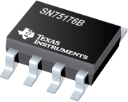
The data-sheet for the SN75176 is available in pdf here.
The classic diagram for connecting this integrated circuit to AtMega is this:
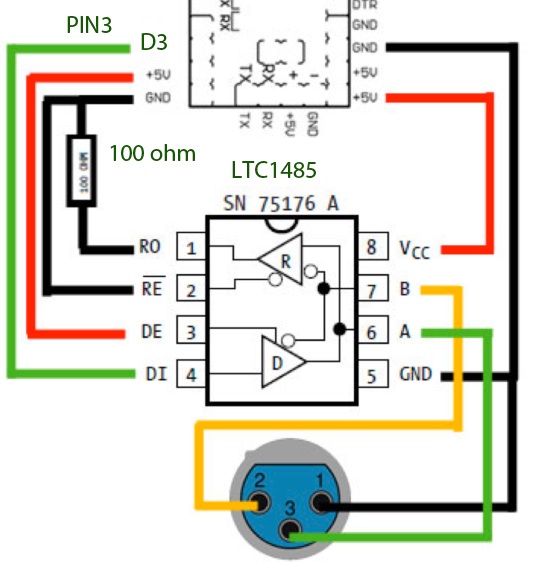
You can see that is not very difficult, using just 1 pin for signal of the Arduino, GND and VCC connections and a XLR connector of 3 pins for interfacing with lights fixtures.
Eagle Ecad Design
Using the FabKit v 0.3 schematic I add the SN7517, you can use the Maxim library in Eagle to add a Max485 smd IC as has the same pinout and trace.
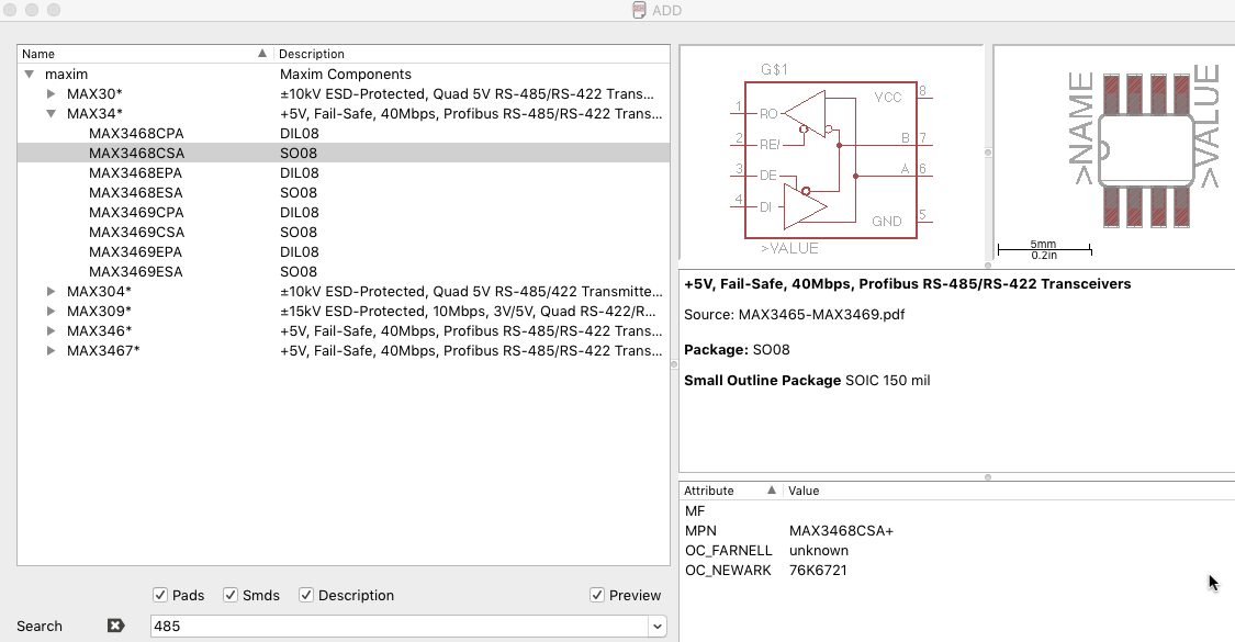
The schematic connections would be like this:
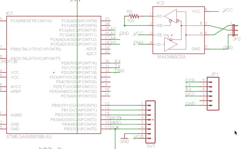
After finishing the paths I notice that I have a free empty space and that I have a full header of pins mostly Analogs ones.
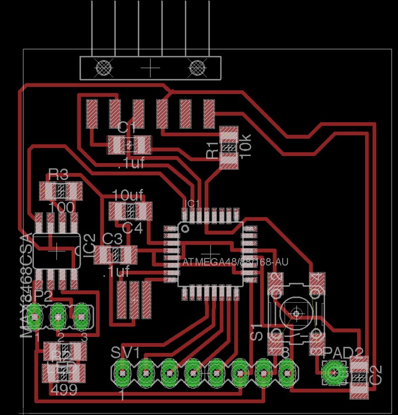
So I also made a header for that A2-A5 pins.
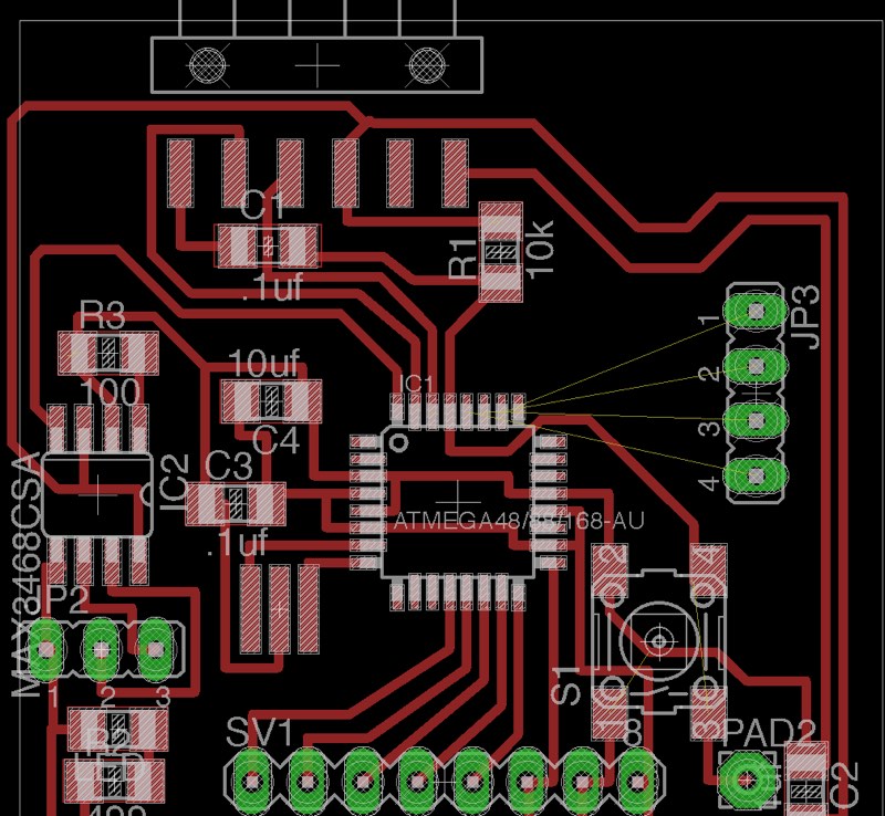
I'm getting a little better in making routes.
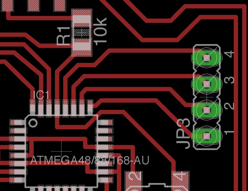
You can download the Eagle Files (Board and Schematic) here.
Images for milling
Here you can download the different images for milling in the Modela the dmxduino
The 64' Traces. Be Aware that path of pin 6 is very near of pin 5 pad and you probably have to remove some material of pad to avoid short circuit.
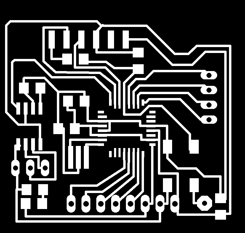
Holes with cut 32' drilling bit.

Cutting Mask that is the same as a normal Fab Kit v0.2.

After milling maybe you can need to just remove some cooper of some little traces in the SN75176 pin 5 pad that is sticky to another path, nothing to worry.
Using long pin headers make a little more difficult to solder and make and stable connecting. I have a little problem with a pin with less tin that didn't let me establish connection with avrdude and Fabkit Dmx so I have to a better soldering.
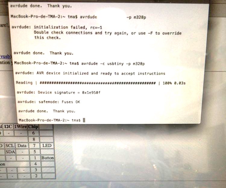
Then I could say hello to the microcontroller and burn the bootloader.
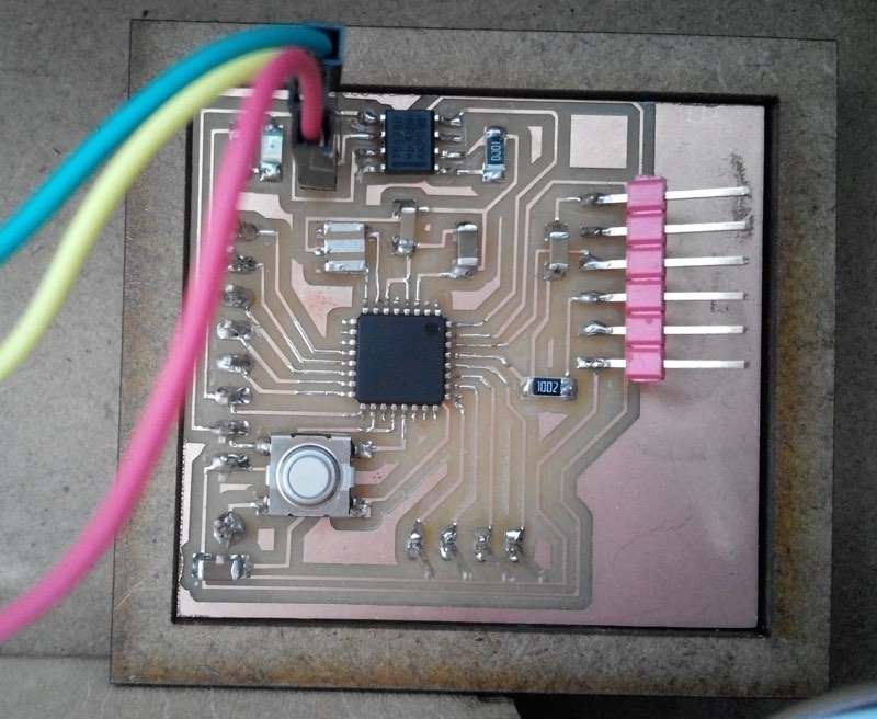
After soldering you have this Fabkit with DMX, also has the modification of an Atmega 328p with 16MHz resonator like an Arduino UNO for programming.
Programming the Fabkit DMX
The Fabkit DMX is like an Arduino UNO, so you just need to download the DMXsimple library to Arduino IDE and start programming. The DMX signal pin is the Digital 2.
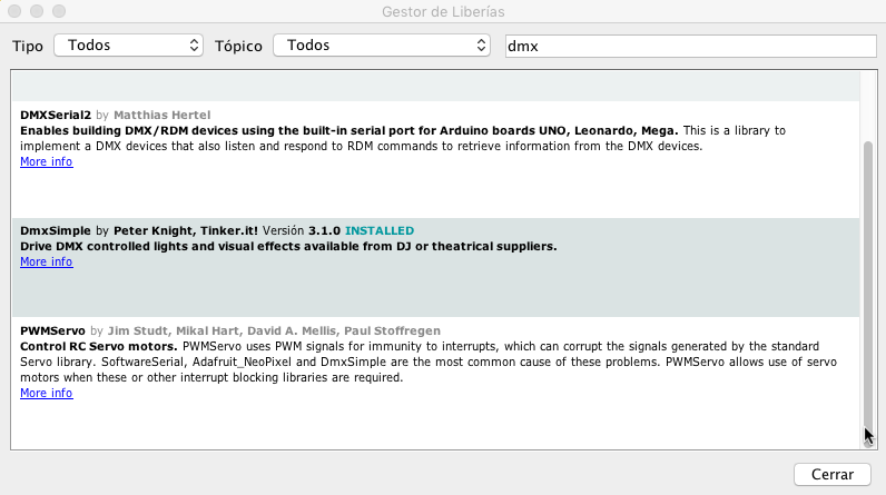
You can download the Arduino ino file of DMX activate with Serial here.
Is a very easy file, Read the serial and if is one byte known send data to a dmx fixture, in this case a chinese one, where 1 channel is light intensity so is always 255, (128 or other values for low or fast blinking), and 2-Red, 3-Blue, 4-Green.
Of course you have to adapt the program to the fixtures you have and how many channels you need, I would be able to manage at least 50-70 channels without problem.
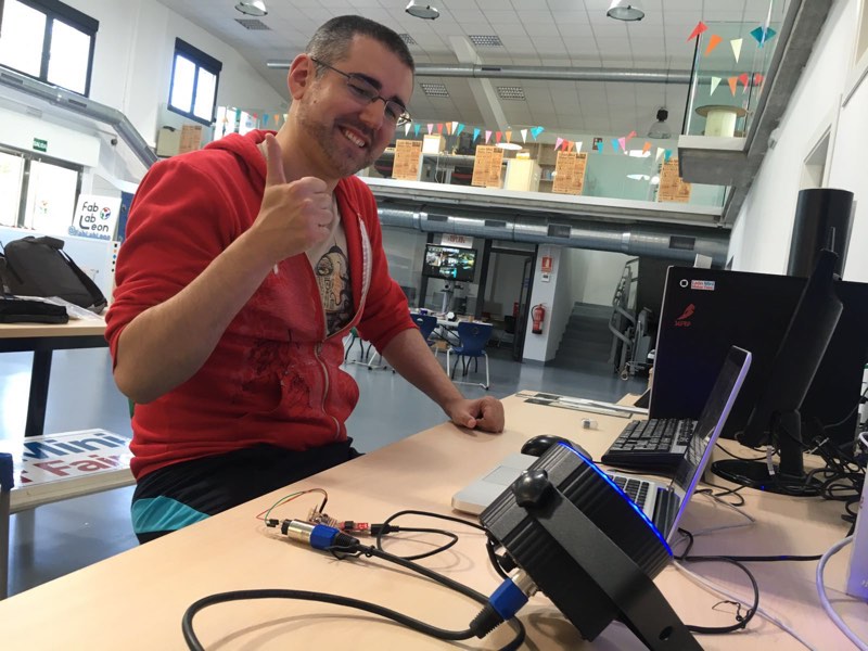
Victory sign because It worked at first try, and I didn't believe my luck to don't have any problem and one important goal was achieved.
