Week 6 - Electronic design
- add (at least) a button and LED (with current-limiting resistor)
- check the design rules, make it, and test it
- extra credit: simulate its operation
- extra credit: measure its operation
- DIY CNC milling machine
- Soldering station
- Multimeter
- Arduino micro ISP
Softwares :
- Eagle A software to design and edit electronic circuits schematics and PCB boards.
- PCB-GCode Plugin for Eagle that allows you to generate Gcode to print, engrave or mill a PCB.
- Fabmodules to generate a G-code from a PNG image.
- 123D circuits Design and simulate circuits.
This week was a very interesting week for me. It reminded me of my electronic class when I was doing my physics studies, 10 years ago, although microcontroller were pretty shyly introduced to students. There is so much power to master these tools, I now understand the vision and the joyfulness of my electronic professor, M. Garnir. It's nice to dive right in the designing and the making of the PCB boards. It really demystifies a lot of concepts. Already having a background in electronics and following some tutorials, Eagle is pretty straightforward to master. Even if I'm well aware that there are still plenty of things to learn ! I took the opportunity for this assignment to refine the CNC milling workflow. I tried to use the fabmodules to generate the G-code to control the CNC milling machine but I had some issues with it. I will try to solve this asap. However, generating the gcode using the PCB-gcode plugin for eagle worked. I discovered that a good board design and smoothening the copper surface prior soldering can greatly help the soldering. I had some soldering issues that I solved with the multimeter. I also had an issue with the microcontroller we used and I had to change it so I could upload a program on it. At the end the led blinked. So, it was a success !!
Some definitions
Here are some definitions of the electronics jargon.
| Term | Definition |
|---|---|
| SMD | Surface-mount technology. |
| ISP | In-system programming. |
Preamble
This week we have to redraw and produce the circuit echo hello-world board in order to explore and familiarize ourself with different electronics schematic and board editors such as Eagle or KiCad EDA (free and open source). It will also be the opportunity to streamline our electronic production workflow. We will also explore numerical tools to simulate our circuits such as 123D circuits from Autodesk.
Before diving into this week's assignment. I analyzed the echo hello-world board documentation and discussed longly with Axel about how to make it. Axel was more than helpful to guide me into this new world, thanks !
The basic board consists of the following items:
- 1 resistor 10k Ohm
- 1 capacitor 1µF
- 1 ceramic resonator 20MHz SMD (crystal)
- 1 FTDI cable, a USB to serial converter cable
- 1 ATtiny44 microcontroller - Wrong one, I started with this one and I had to replace it with the ATtiny84.
- 1 ATtiny84 microcontroller - Good one
- 1 6 pin header
I've decided to add:
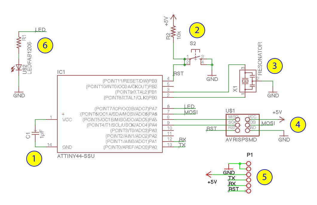
Here is the list of the selected components with their symbols.

Which resistor do I need to use to limit the current in the led ?
Reading the green led datasheets, it says that the forward voltage is typically 2V and the forward current should be 20mA. The power supply delivers a voltage Vcc=5V. We need to place a resistor in series with the led in between a high voltage pin (5V) and the ground GND. The role of the resistor is to limit the voltage to (5V-2V) on both side of the led and limit the current to 20mA. The Ohm law gives V = I*R (Tension = current x resistance). In consequence, we should chose a resistance close to R=(5V-2V)/0.02A=150 Ohms.
Drawing the echo hello-world board in Eagle
To draw the circuit board I chose to use Eagle as it is what my close collaborators use and I would like to learn a common language. Also the free version of Eagle is more than enough for an hobbyist or a tinkerer.
First, I downloaded and installed Eagle.
Then I uploaded two libraries that I will need to draw the circuit (see source files).

Electronic components in Eagle
Each component in Eagle is represented as a device that includes a symbol that can be used in the schematic view and a package that is used in the board view

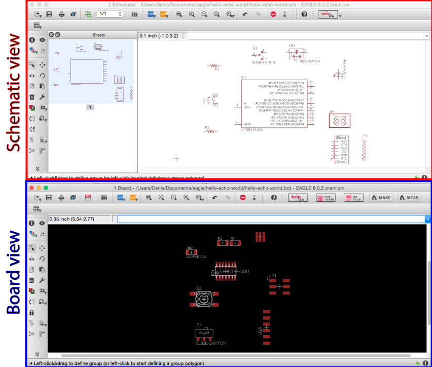
Schematic and board views in Eagle
In Eagle, there are 2 views, one schematic view to draw the electronic circuit schematically which is linked to a board view that is used to print the circuit board.
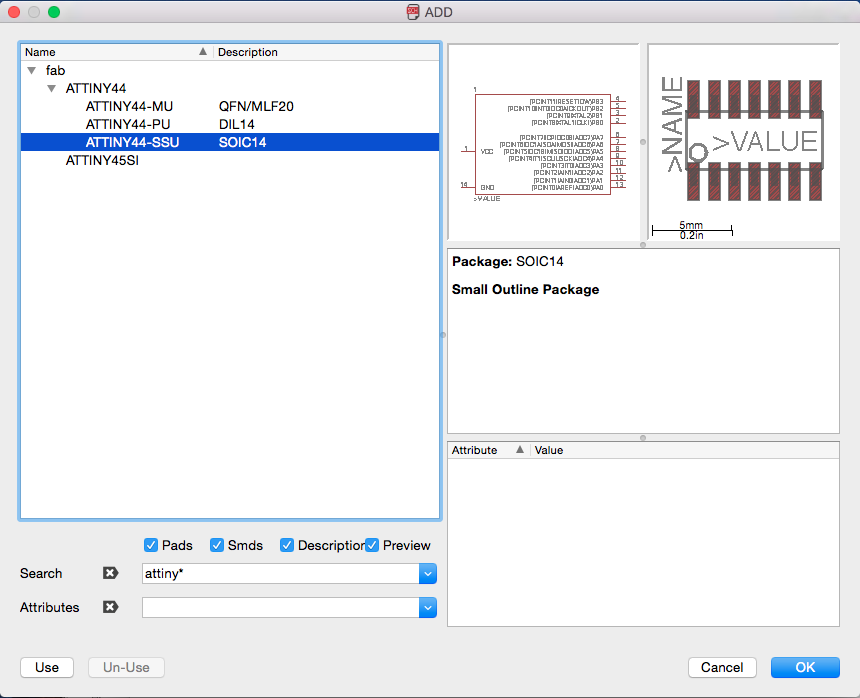
Uploading all the components in the schematic view
Then, I uploaded all the components in the schematic view. For example, to add the ATtiny microcontroller on the schematic, I clicked on the icon "add a part" in the schematic view and searched for "ATtiny*" in the ADD panel. Then, I selected the microcontroller that I have and clicked "ok" to add it in the schematic view.
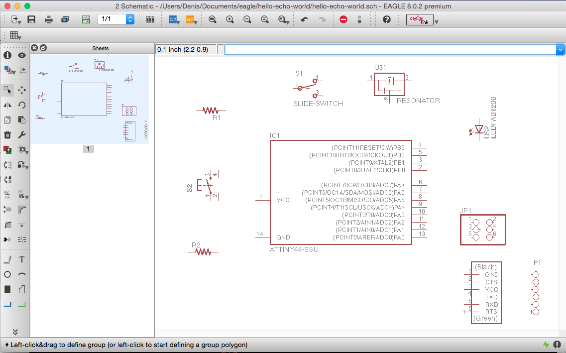
Here is the schematic view with all the components.
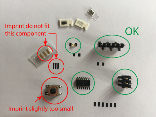
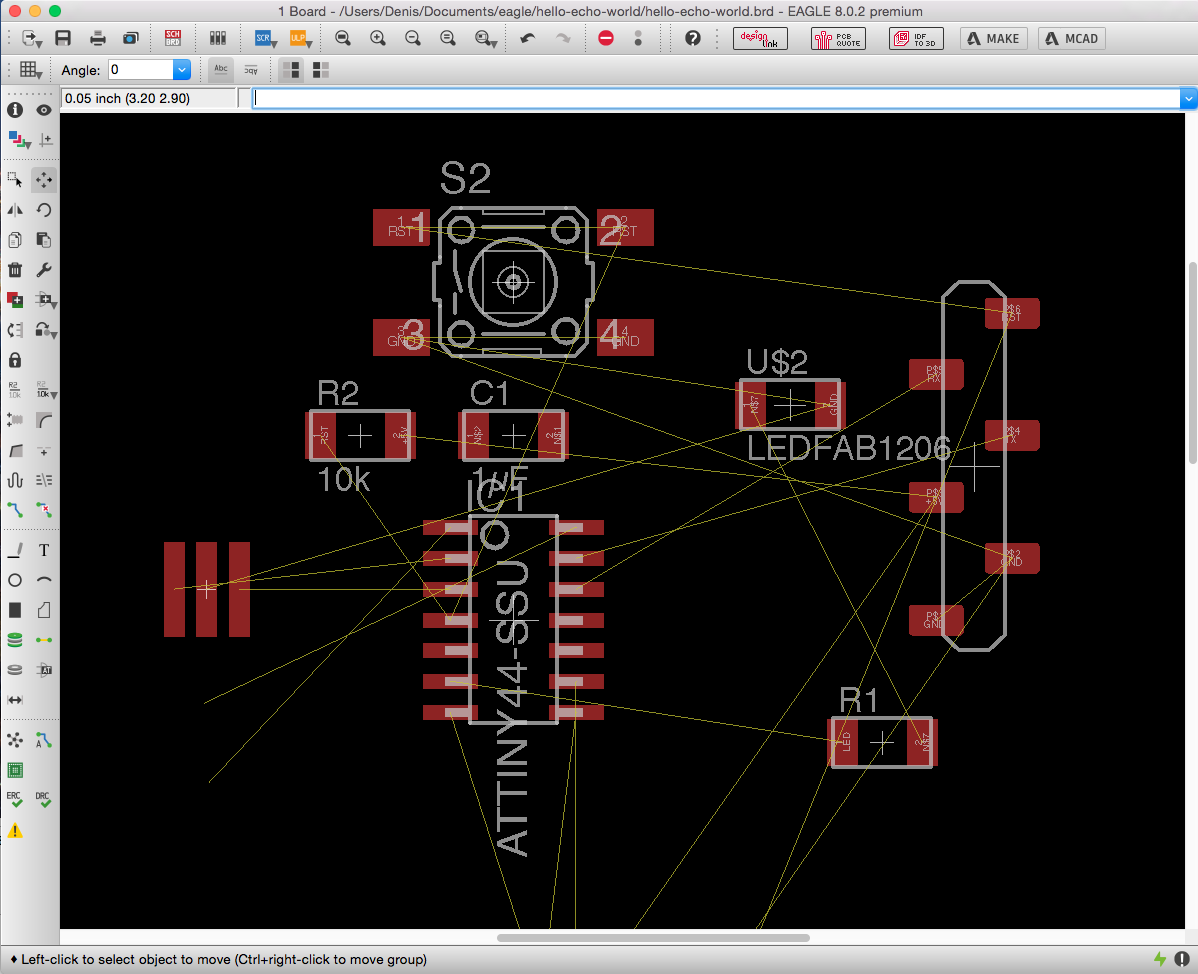
Checking the board imprint of each components in the board view.
I have printed the board on a white paper using a laser printer. I then checked that all the components were fitting on their respective imprints. As you can see the ceramic resonator and the button are not well adjusted on their imprint. For these two, either we selected the wrong components in the library, either they do not exist yet and we have to adapt the imprint (package) to fit our components. We are going to modify the package file slightly.
Modifying the package
To adapt the package file of the resonator, we checked on the electronic component website the datasheet of the resonator. We see on the left of the image here below, that the connectors are separated by a distance of 1.27mm, the datasheet, says it should be 2.5 mm so let's change the package. We will do the same for the button.

Building the circuits in the schematic view
- I linked the capacitor 1µF in between the GND and the Vcc of the ATtiny microcontroller, to short cut the high frequency current noise. Some parts of the circuits can act as an antenna and high frequency noise can be generated within the circuit.
- I wanted to use a button to restart the program of the microcontroller each time I will push on it. I placed a button in between the ground (GND) and the reset pin of the microcontroller, I made sure to place a pull-up resistor to keep the reset pin high (5V). When the button will be pushed, the pin will be set to 0 and the program on the microcontroller will restart.
- Then, I've added a clock to the microcontroller. I've connected the resonator to the 2 pins of the microcontroller that are dedicated for that.
- I've connected the ISP 2x3 pin-header to the microcontroller.
- I've connected the microcontroller to the 1x6 pin header for the FTDI cable.
- Finally, I added a led with a current-limiting resistor in parallel and connect it to the GND and the PA7 of the microcontroller.
Designing the board
The rule of the game here is to place the different electronic components on the board and make the link between the pins that should be linked. Based on the schematic, the yellow lines show the connection that should be made in between pins.
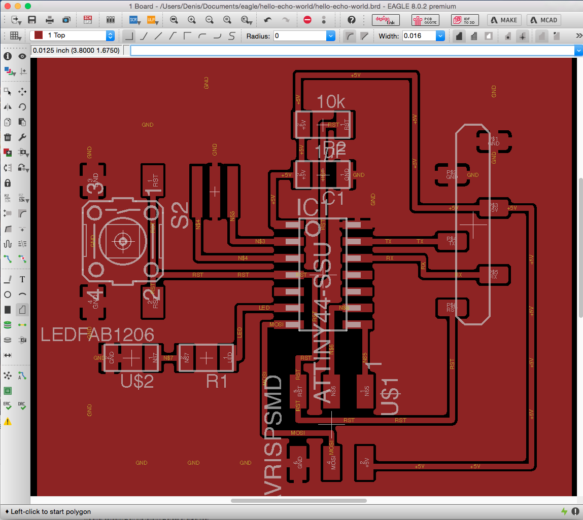
Once all the electronic components are placed and the links are made, I wanted to create a metallic shield connected to the ground (GND) around the circuit. To do that I typed "polygon GND" in the command entry below the top bar and clicked on "Enter". Then I drew a rectangle around the circuit.

Then I clicked on the "rastnet" button on the side bar to fill the rectangle with solids that should be connected to the GND.

Here is a close up view for the details.
Making the PCB
In order to make the PCB, we chose to mill the PCB with our CNC milling machine. Last time, we used the PCB-GCode plugin for Eagle to generate the G-code. This time, I wanted to test the Fabmodules.
The fabmodules will produce a G-code for the CNC milling machine from a PNG image file. Different PNG images have to be produced if we want to engrave and drill or cut the PCB.
Exporting the Eagle board layout in a PNG image
To export the PNG image from Eagle, first I selected the top layer in Eagle.
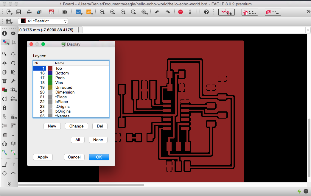
Then, I exported the image using the export option in Eagle.

In the panel make sure to select monochrome and set a resolution of 1000 dpi.

Here is the PNG image file produced. The black area will be cut while the white area will remain untouched.

Using the Fabmodules to produce the G-Code.
I then went on the fabmodules web page. Be sure to use the chrome browser to do that, it seems t have issues with other browser. I uploaded the image and choose the output as "G-codes (.nc)". To process the G-code, I chose "PCB traces (0.010)" I let the default parameter and changed the tool diameter to 0.3mm. I calculated the G-code and uploaded in WinPC-NC the software that is controlling the CNC milling machine.
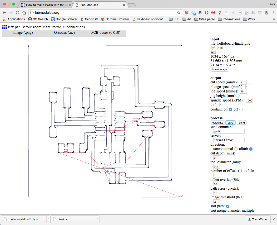
From there, I had a problem. It seems that the software cannot interpret the G-code. It reads it with imperial units instead of metric units... I'm stuck !!!
Back on Eagle to produce the G-code
As I'm stuck with the Fabmodules, I went back on Eagle and used the PCB-GCode plugin for Eagle. This worked and I produced the CNC milled board.
Soldering the electronic components
Here are all the components prior soldering.
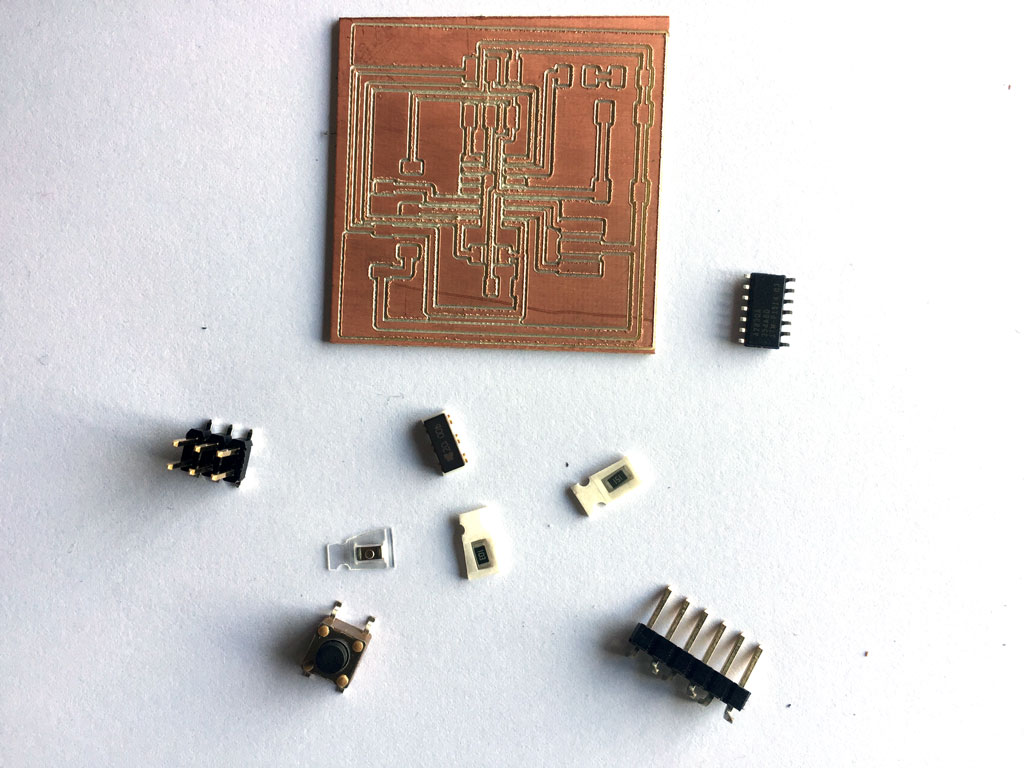
Last time, I soldered on chemically etched PCB board and it was much more easy. Here with the CNC milled board there are some roughness coming from the engraving. I should have smoothen a little bit the board before soldering the components. It's for next time. I also observed that a good design in Eagle can ease the later soldering. Some pins were much harder to sold.
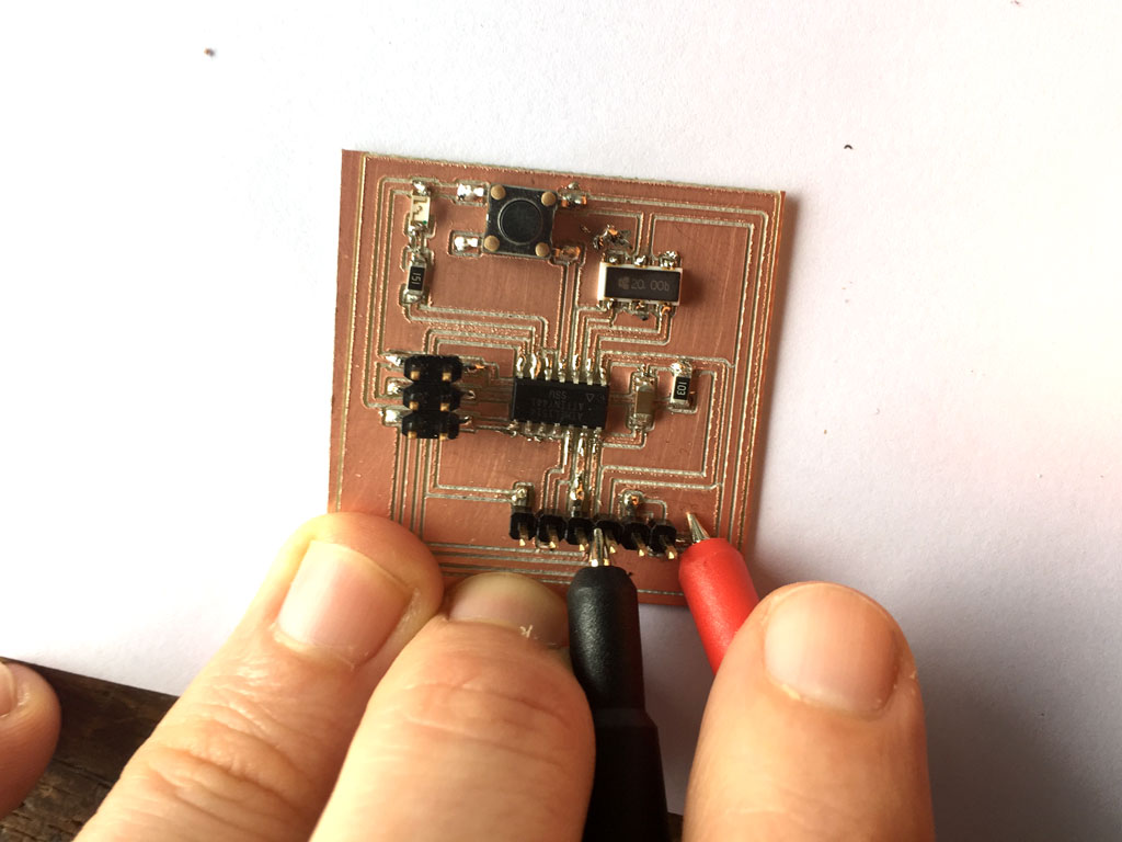
To check the soldering and the connections, I used the multimeter on the "sound mode" so it will make a noise if two parts of the board are connected. I had a problem with the soldering of one of the pin header. The metallic shield was connected to the ground and the Vcc. I remade the soldering and mend it.

Testing the PCB and uploading a program on the microcontroller
Using the Arduino micro ISP, I tried to upload a program.

To do that, I used the Arduino IDE. I opened the simple "blink" program to test the microcontroller. I just changed the led pin number to 7.

To connect my ATtiny, I had to upload additional board manager in the Arduino IDE. I have followed this tutorial.


Then I set the microcontroller parameters in the tool tab and uploaded the program.

Problem !! I used the wrong microcontroller... The ATtiny44 we selected has a external clock limited to 16MHz and we are using a 20Mhz. We thus had to change the microcontroller and use a ATtiny84 instead. Let's unsolder the wrong one and solder the good one...

The led is blinking, it is working !!!

Board troubleshooting - reset
While I was testing the serial communications using a FTDI cable on week 8, I discovered that something was wrong with my board. In fact on the schematic of my board, here above, we can see that the FTDI reset pin is directly connected to the reset pin of the microcontroller. This means that each time I connect the FTDI cable, the program on the microcontroller is erased. Looking into that problem with Axel, we found that adding a capacitor in between the FTDI reset pin and the microcontroller reset pin solved the problem.

Simulation using 123D circuits
This is just amazing. You can make and simulate circuits using 123D circuits. Even more you can program the microcontroller and simulate it ! Here is a little circuits I've tried.

Here is the breadboard
Here is the corresponding schematic
Here is the corresponding PCB