Week 13 - Input device
- Soldering station
- Electronic components to make the Satchakit (ATmega328P, resistances, capacitors, leds, crystal, button and pins)
- Oven (up to 250°C)
- Acetone
- Soldering paste
- Arduino
- FTDI cable
- flex sensor
Softwares :
- Arduino idea
- Autodesk Eagle
Electronic weeks are highly non linear in the way we complete the assignment. There are so many things to learn (theoretically and technically), so many steps and so many things that can go wrong when doing electronics that we have to be quite organize in the way we plan to complete the assignment. I first focused on how the flex sensor works and what needs to be build in order to read something from it. Then I focused on the ADC converter of the ATmega328P microcontroller and used the datasheet to understand how it works. I then learned and practice a new technique for soldering electronic components on a board using soldering paste and an oven. I also tried another way to program the board that was newly made using an Arduino as ISP. I learned to burn a bootloader and use a FTDI cable to program the board and read values from the sensor with it. Most of all, I struggled a lot on debugging my electronic systems which really spiced up the learning process !
Reproducing the Satshakit
As a start, I wanted to create a microcontroller board that is sufficiently universal to test and learn electronics in more depth but also that will be useful to develop my final project. The Stashakit is a good way to start as it is one of the simple Arduino design, here is the link to the tutorial.
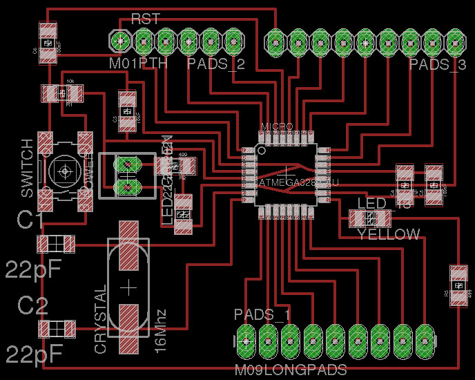
Here is the board designed in Eagle.
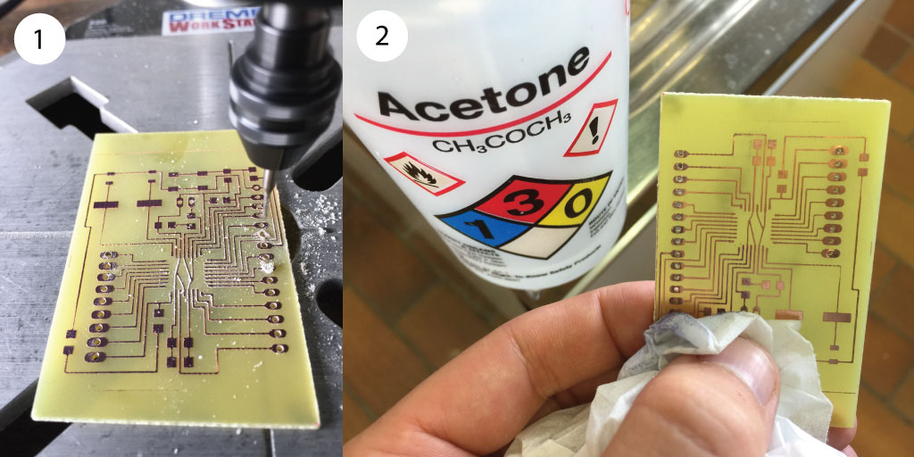
Here is the pattern that we chemically etched to produce the board.

Oven soldering
To make this board I wanted to try another soldering process that Axel (in my lab) tutored me on which is oven soldering. After having made the copper etching with the process explained on week 4, (1) I used the drilling machine to make the pin holes. I then used acetone to remove the remaining photosensitive resin. This last step is done at the end as the resin protect the copper from oxidation until the very end before soldering.
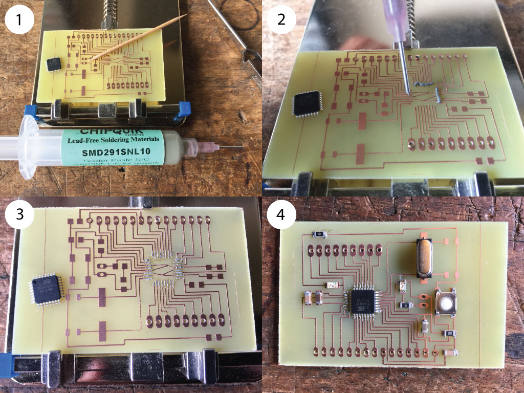
I then used (1) soldering paste that (2-3) I've spreaded on the copper circuits. (4) I then place all the electronic components on the board. A rule of thumbs to check if there is enough soldering paste for the components: they should not fall when the board is put upside down.
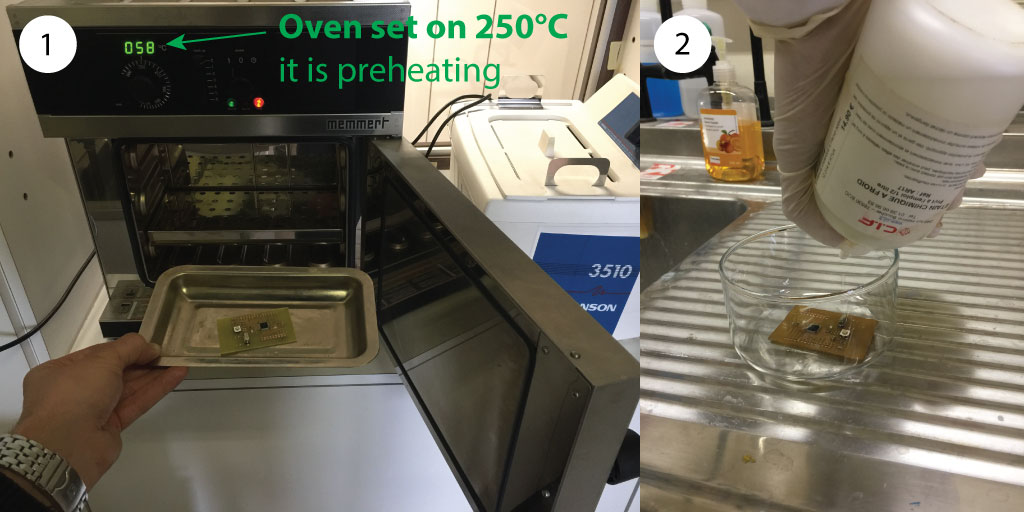
(1) I then put the board in the oven for 15-20 minutes. (2) Then while the board is still hot, we let the board soak in a tin plating liquid for about a minute to coat the oxidized copper with a thin layer of tin. This last step ease the final soldering step (for few of the components that we still have to sold).
Here is the board ready for soldering the remaining pins. The pins were not sold using the oven soldering method to be sure that they will not fall in the oven while heating the paste.
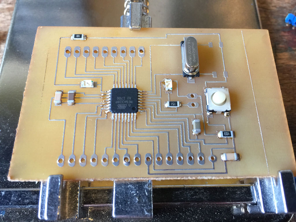
(2) I then placed the pins that I had to sold.

And this is the final board !!

Stashakit modification
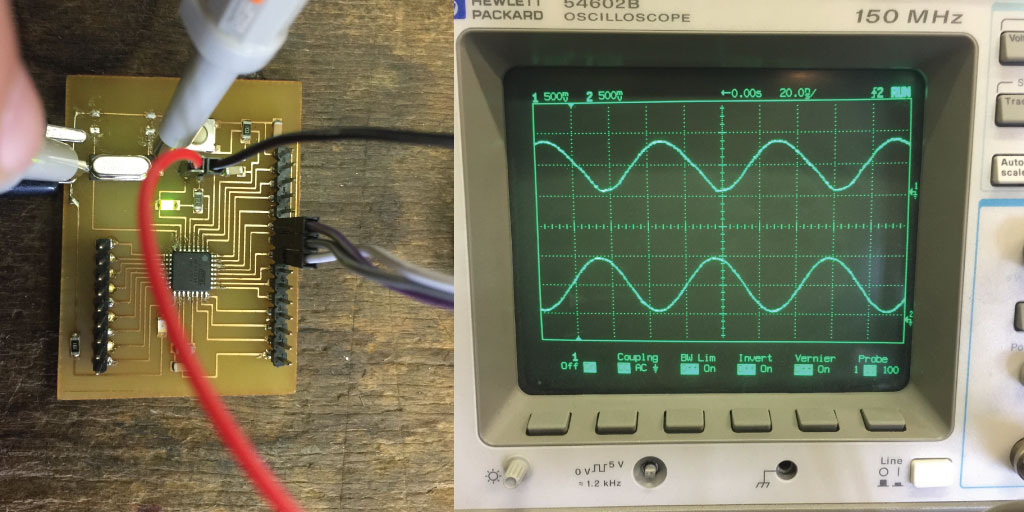
During the debugging phase, we found that the capacitors cutting the crystal noise were probably a problem. So, we removed them and we could upload a program and burn the bootloader. I then used an oscilloscope to check if this procedure affected the signal coming from the crystal and it seemed ok.
Uploading the bootloader
Using Arduino as an ISP
Last time, I used the fabISP that we made to program the microcontroller. This time I wanted to try to use the Arduino as an ISP so I can learn different ways of doing one thing. This procedure is also explained in the Satshakit tutorial.
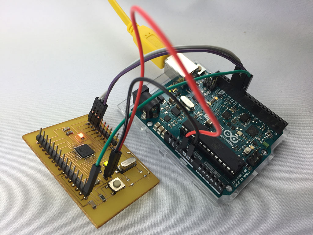
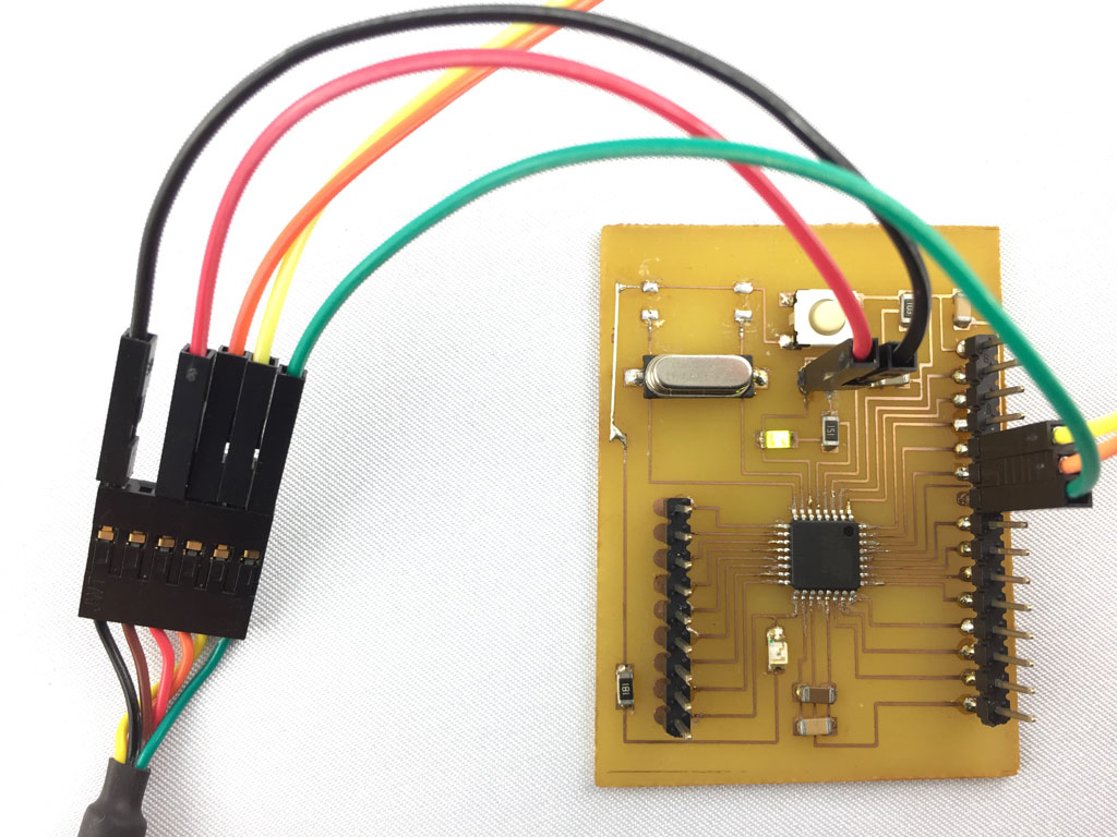
Make the connections as shown on the picture below.
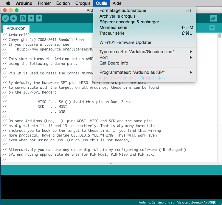
I've uploaded the the ArduinoISP sketch on the Arduino that I will use as an ISP.

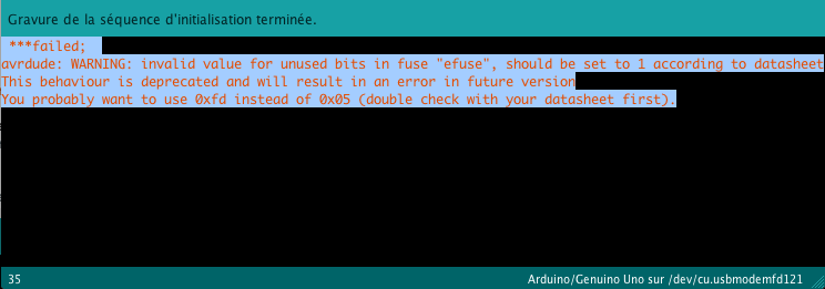
Changing the "board type" to arduino (ATmega328P) and the "programmer" to "Arduino as ISP", I then burned the bootloader on the board that I have designed.
An error message will appear but it seems to be a warning which does not affect the burning of the bootloader. An important point, is that we had to remove to capacitors from the satshakit design so we could make it work...
Uploading a program using the FTDI cable
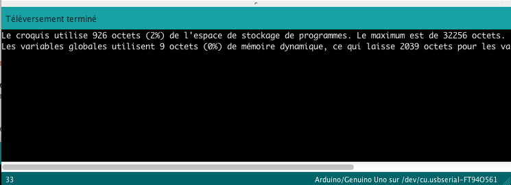
Once the bootloader is burned on the ATmega328 chip, I could upload any program using the FTDI cable.
And it worked !
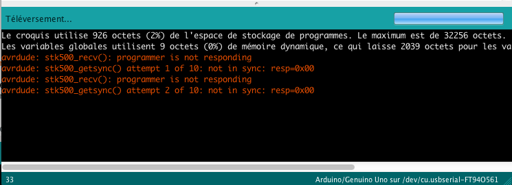
One weird thing, on my computer when I want to upload a second program after I have uploaded the first one, it says that the programmer is not responding. To resolve this issue, I have to unplug and plug again the FTDI cable. And it works again. It is weird, as using another computer with exactly the same FTDI cable and connections, it was totally working fine...
Flex sensor
For this assignment, I used a flex sensor as displayed below. It is a variable resistor which resistance change when we bend the sensor. When the sensor is flat, the resistance is at a value of 10kOhms.

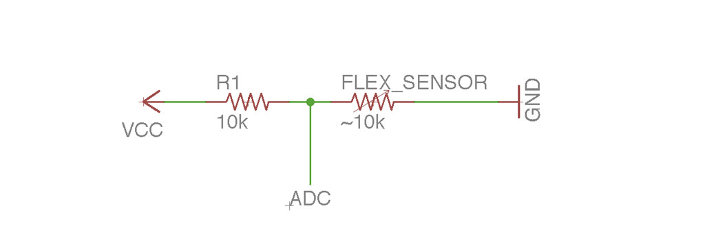
To read the resistance value from the sensor, we need to build a voltage divider as shown below with a resistance of about the same value as the sensor (when flat, ~10kOhms). Using the ADC of the ATmega328 on the microcontroller board that we made, we can measure the voltage value in between the sensor and the fixed resistance. When flat, it is 2.5V as the resistance and the flex sensor have the same resistance value. When we bend the sensor, the voltage value changes and the ADC (Analog to Digital Converter) can encode the voltage value. As can be found on the ATmega328P datasheet, the encoding is made on 10 bits which means that the voltage is sampled in between 0 and 5V on 1024 values.
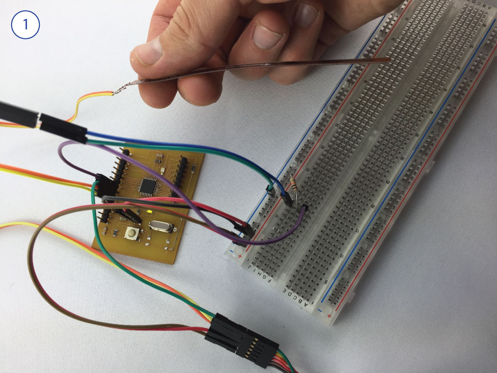
Using the FTDI cable and the Arduino IDE, I have uploaded a simple program I made. This program establishes a serial connection in between the board and the computer, digitally converts the analog voltage value in between the sensor and the 10kOhms resistance, and print the value using the serial connection. We can see the recorded value on the figure here below on the right. Note that an encoded value of 0 is 0V and an encoded value of 1024 is 5V. (1) the sensor is flat, the encoded value is 1024/2=512. (2) When bend in one direction the voltage value decreases which means that the sensor resistance decreases also. (3) Finally, when the sensor is bent in the other direction, the voltage increases, meaning the flex sensor resistance increases also.
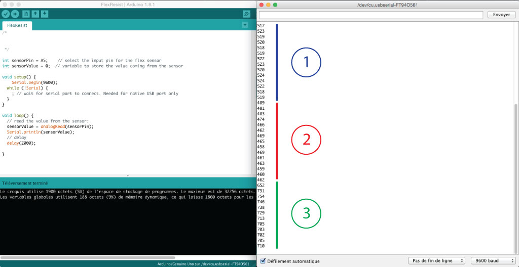
The sensor is flat, the voltage value is at 2.5 V.
The sensor is bent, the voltage value decreases as the flex sensor resistance decreases.
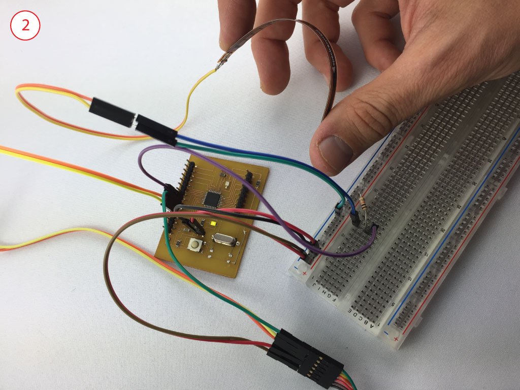
The sensor is bent in the other direction, the voltage value increases as the flex sensor resistance increases.
