Week 3 - Computer-Controlled Cutting
- make lasercutter test part(s), varying cutting settings and slot dimensions
individual assignment:
- cut something on the vinylcutter
- design, make, and document a parametric press-fit construction kit, accounting for the lasercutter kerf, which can be assembled in multiple ways
- Laser cutter Epilog Laser MINI 24 60W (600 x 300 mm)
- Laser Cutter Cyborg LS-1080-K 60 watt (1000 x 800 mm)
- Roland CAMM-1 GS-24 Desktop Vinyl Cutter
Softwares :
- DraftSight 2017 a free software for 2D designs
- Corel Draw For 2D design and used as an interface with the laser cutter.
- Fusion 360 for 3D parametrical design.
- Solidworks for creating, assembling and animating
3D parametric design is really powerful as you can create a very productive workflow that really makes sense for the digital fabrication age. I learned to explore different tools 2D and 3D design tools. Depending on the parameters I wanted to control, I would choose the best workflow. There is always a trade in between simplicity and flexibility. Once I have finished my design, I would have liked to start over and make the workflow more elegant and I'm sure I would do it much much faster. Mastering your tools and being "elegant" in the way you design your workflow empowers you and allows you to save plenty of time. More importantly, it opens up new possibilities and gives you plenty of new idea for future design.
Group assignment
In Brussels, we are a team made of people coming from very different fields with very very different style and way of working. So, the difficult and really challenging part being to coordinate team works. The bright side is that the group energy is really high and we can help each other in fields that we are not comfortable with. We tend to always find a solution to a problem. And as a team we try to push each other to fulfill the assigned goals. So part of our work is to learn to work together and see how far we can go...
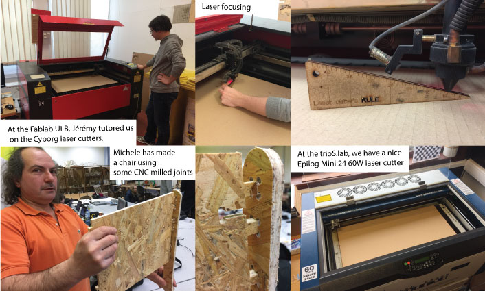
At the Fablab ULB, we have 2 huge laser cutters Cyborg LS-1080-K 60 watt that are usually used by the students from our University. Jérémy showed us how this machines that quite basic function. The good part about this machine is that they are cheap and have a huge cutting area. However, the laser settings for cutting very a lot from day to day depending on the room temperature and humidity. Also the focus has to be done manually.
In my lab, we have a small laser cutter - Epilog Laser MINI 24 60W, this machine is quite expensive but is really stable and reliable. I am really happy with it.
Laser cutter parameters
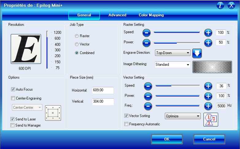
To test the laser kerf, I designed some squares with joints in Corel Draw. To cut them using the laser cutter, we just have to print the drawing as if it was a regular printer but selecting the printer "Epilog Mini+". To set the cutting and engraving parameters, click on preferences.

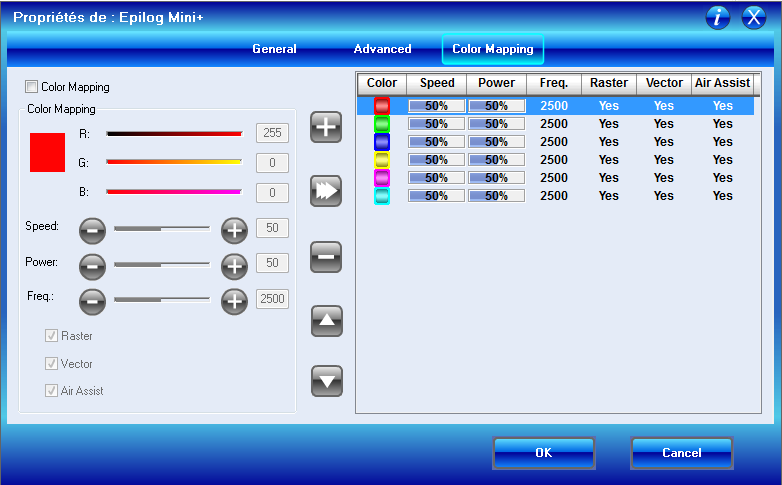
This panel opens where we can choose to activate the autofocus (the laser will focus automatically on the material we want to cut); choose the job type to be raster (it will engrave filled areas on the drawing), vector (it will cut along lines on the drawing) or combined (it will engrave and cut). We can set the power and the speed of the laser independently for the raster setting job or the vector setting job.
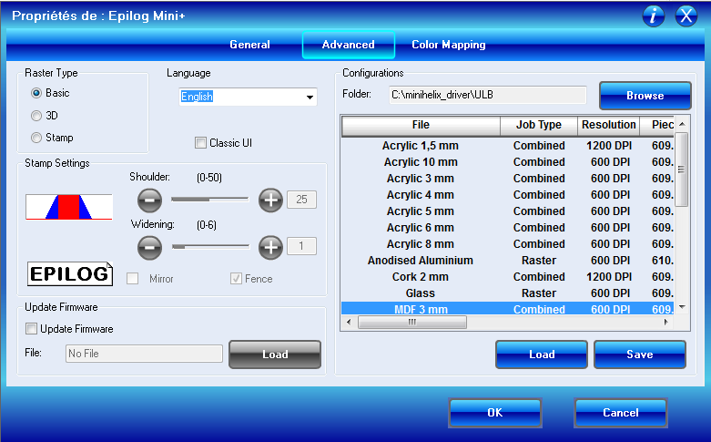
By clicking on the advanced panel, we can upload preset parameters that are optimized for different materials and thicknesses.
On the color mapping panel, we can set different parameters for different colors. That's what I did here, I used different speed and power settings to see their effect on the kerf. But the kerf didn't change so much with the power and speed parameters so I used the following parameters: power 100% and speed 100 %. That was fine to cut cardboard.
Measuring the laser kerf
We started by designing simple pieces to test the press fit joints and see how the laser kerf was affecting them.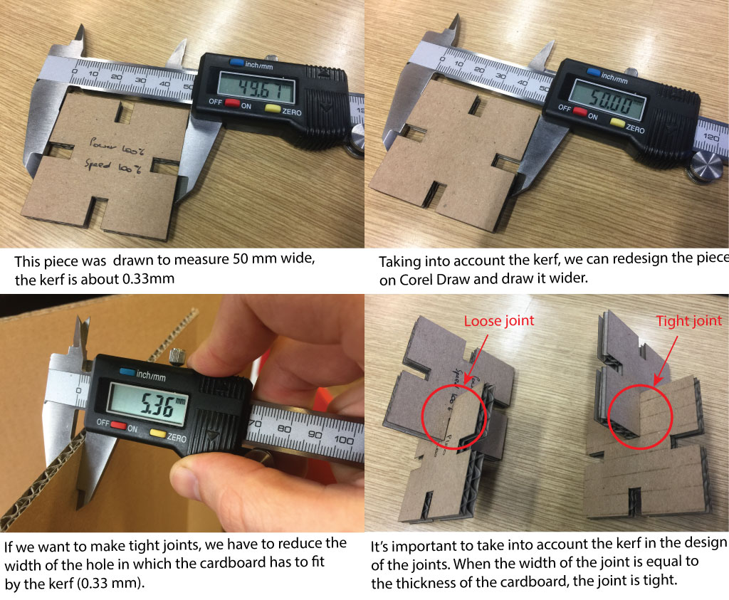
Designing the press-fit kit
For the press fit kit, I chose to draw a lamp shade. I thought about using several 2D drawing tools, I thought about Corel Draw, DraftSight and Illustrator. Inkscape is not easy to use on a mac (I might try to install a linux virtual machine and try it again on the VM).
Designing the object parts on illustrator
I wanted to start with something simple and useful. I needed some lamp shades for my home. I decided to do a lamp shade with an axial symmetry so I could start designing my lamp in a 2D software and print it from that software. Then I would export my 2D files to Solidworks and make the 3D drawing.
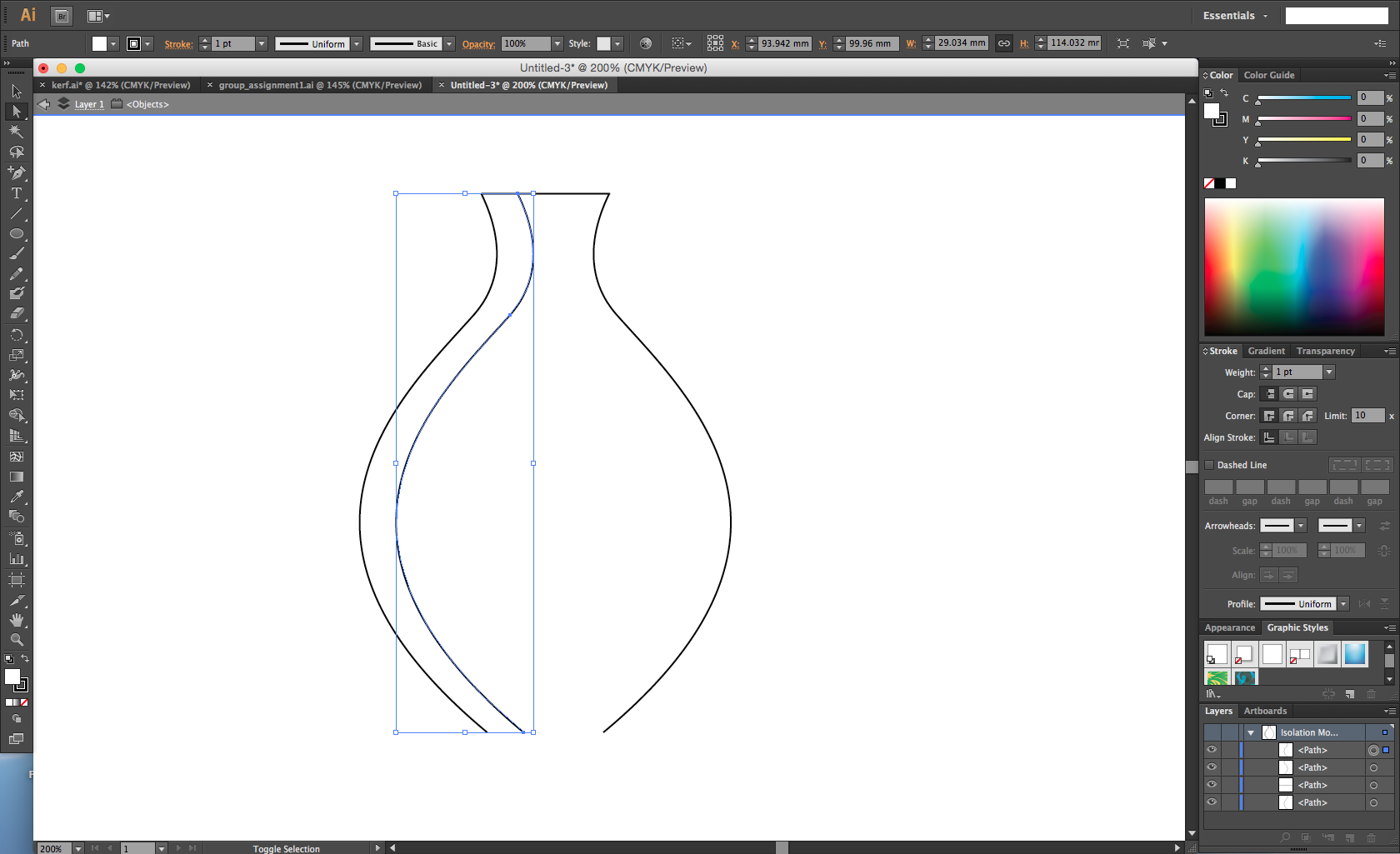
side view
First let's start with a drawing in illustrator. Using the pen tool I designed the vertical blades that would be press fitted in some horizontal disks.
top view
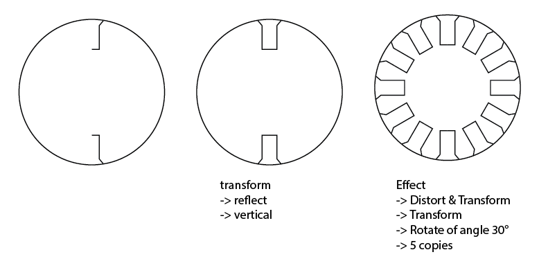
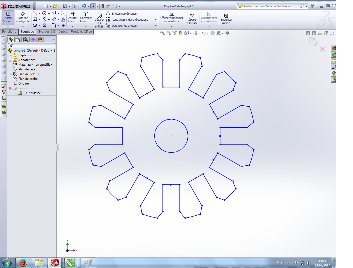
Then I designed the 2 disks in which we would press-fit the 12 blades. To design the joints, I wanted to use a parametric design so I could modify the width of the joints if the laser kerf was different. To do that, I designed half a joint (width=("thickness of the cardboard" - "kerf")/2) that I mirrored around the vertical axis. Then I applied a transformation effect, I created 5 copies of the couple of joints with a rotation in between each copies of 30°. Now I need to modify the joint path on the first drawing to change all the joints at the same time. That's a semi-parametric drawing. It's not yet fully parametric like it could be in Solidworks but that's already pretty fine as we only need to tweak some dimensions on the drawing to make it cuttable on any laser cutter with any materials (the kerf would be different when changing the laser cutter and the material that is cut).
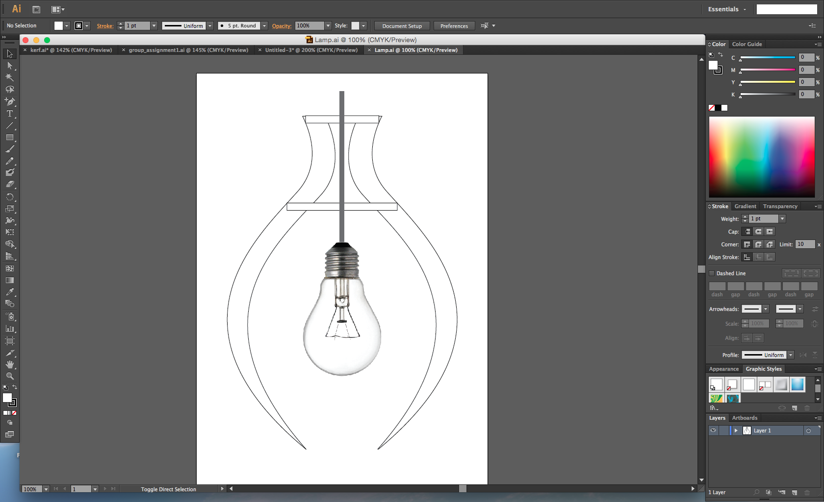
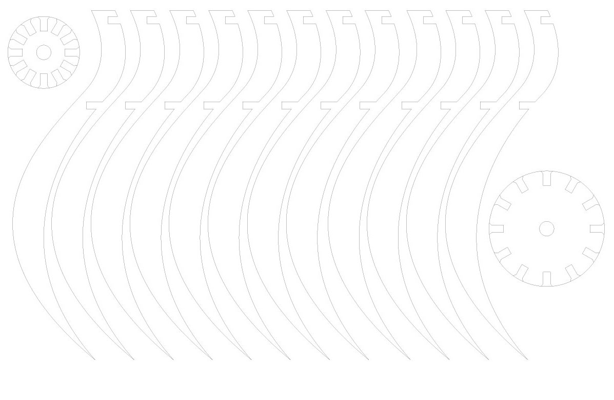
Here is the file that we have to print.
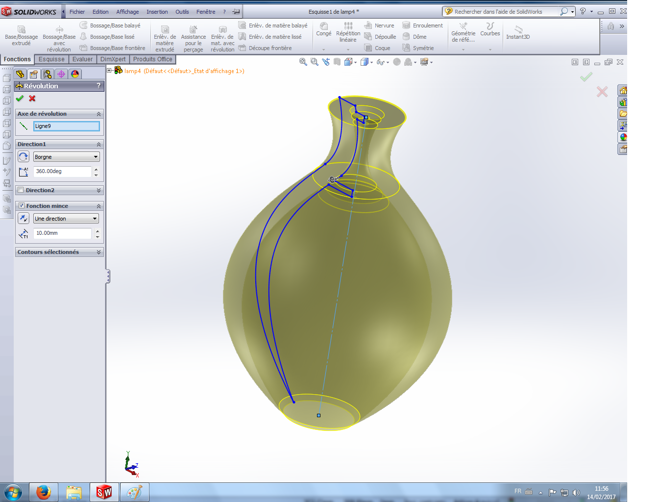
Designing the 3D object on Solidworks
My lamp is made of 14 parts with 3 different designs. Using illustrator, I've exported the 3 different files in DXF. Then, I opened Solidworks and started a new sketch and inserted the first DXF file.
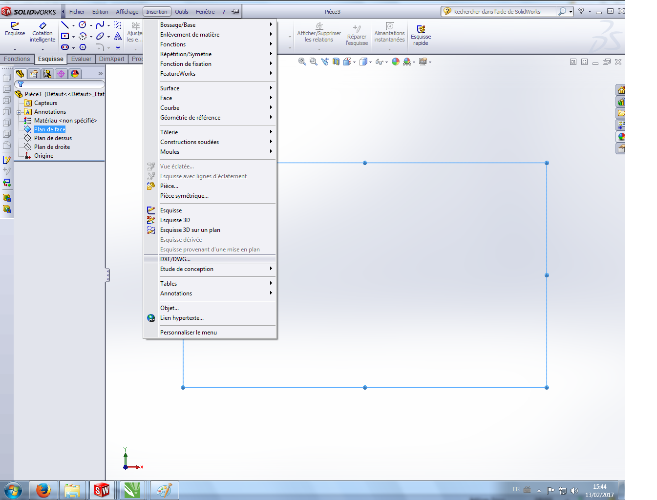
Here is the imported file.
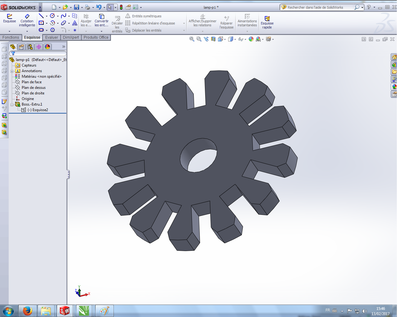
Then, I just needed to extrude the sketch on a distance that is equal to the cardboard thickness. I must admit that I spent some time tracking the lines that were not joined in illustrator and I had to joined them in Solidworks so I could use the extrude boss/base function. Here is one of the pieces in 3D.
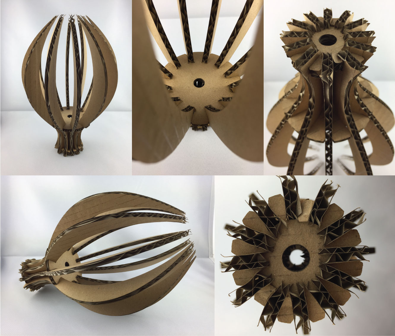
I then made the 3 different pieces in Solidworks and assembled them.
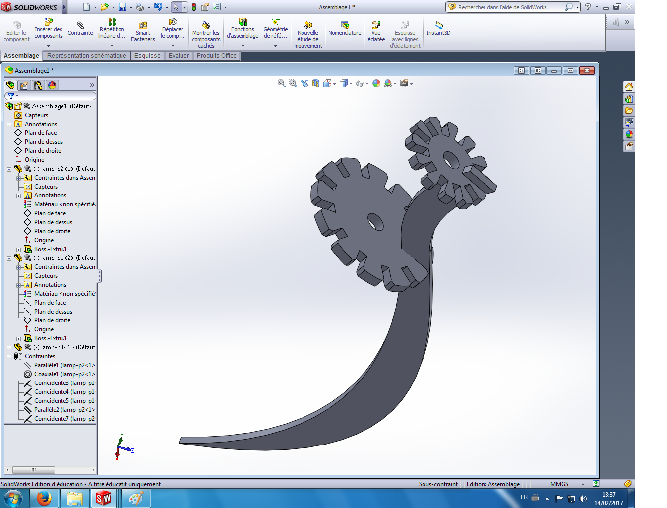
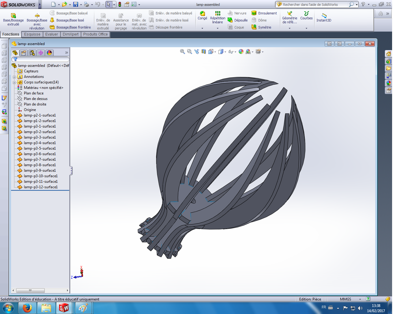
I did a rotational repetition for the blade and finished my lamp that is pretty nice.
A parametric design
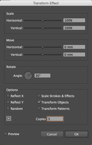
I wanted to create a parametric workflow that allows me to change the joint thickness accounting for the laser kerf. This kerf depends on the laser cutter that is used and on the material that is used too. To change this joint thickness, in my workflow, I just need to length of a few joints in my illustrator design and all the other joints will change accordingly to that change. To do that I used a "Distort and Transform" effect in illustrator. Then I just have to cut it using the laser cutter. In this case Solidworks was used to represent the lamp in 3D.
Aldo (from the fablab in Barcelona) showed us how we could make the lamp directly in 3D with Rhino and Grasshoper. The great thing about this workflow is that you can control more parameters such as the number of blades. The joints are calculated automatically. However mastering these softwares to do that is a requirement. The software and the workflow that should be chosen really depend on the parameters that need to be controlled. In my case, it was the thickness of the joints. I would however like to go further in the 3D parametric design to learn and become a master in those tools. But to do that, I will concentrate on really simple structures to assemble.
A plain lamp for Victor
I made a plain lamp for my teammate Victor who will try to make another lamp model using 123D-make.
Cutting the parts with the laser cutter
To physically create the lamp. I just needed to start from the illustrator file presented here below and "print it" using the laser cutter. Here is the laser cutter cutting the parts.
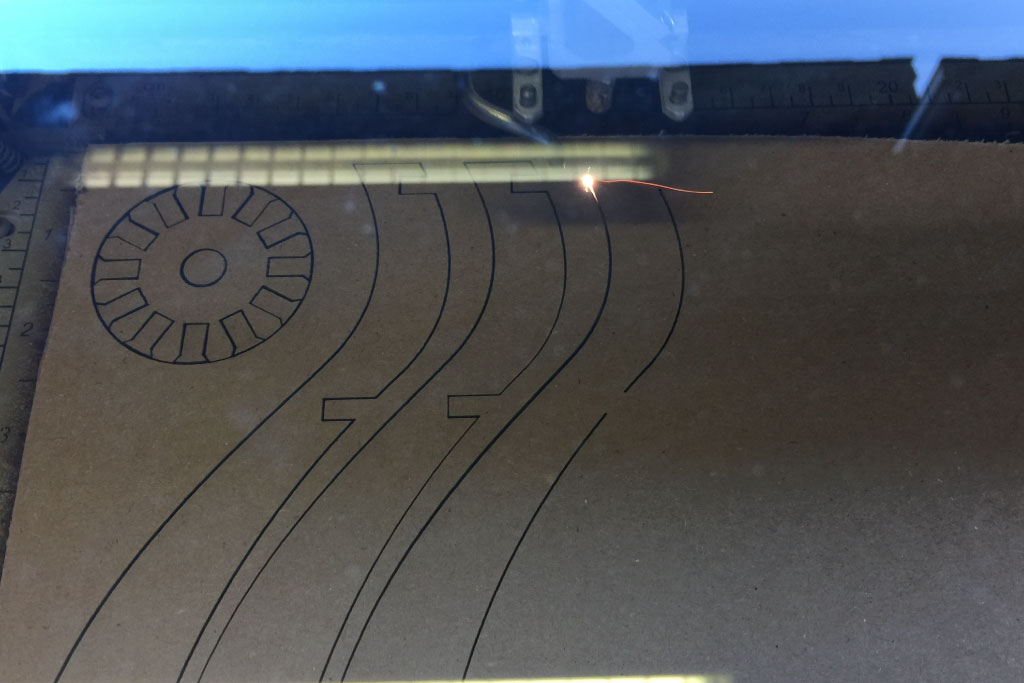
Here is a video of it.
And here are the parts ready for assembling.
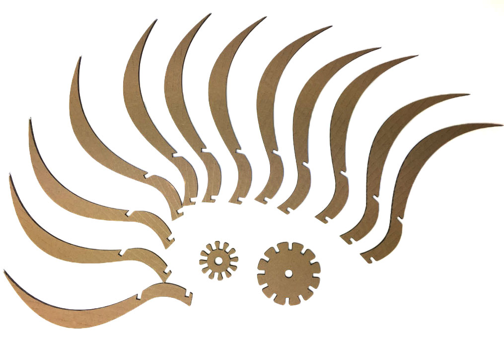
And here are the parts ready for assembling.
Cutting something with Vinyl Cutter
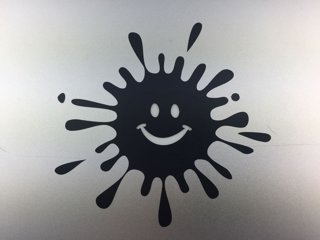
As an introduction to the Vinyl cutter tool, I wanted to create a sticker for my computer. To cut something with the Vinyl cutter, we need a vectorized image. So let's start by doing that. I've found two images of a splash and a smiley that I would like to combine. I used illustrator to do that but inkscape could be used too.
Vectorizing the outline of an image in Illustrator
Let's upload an image found on the web that I like in Illustrator. I will show how I vectorized the outline.
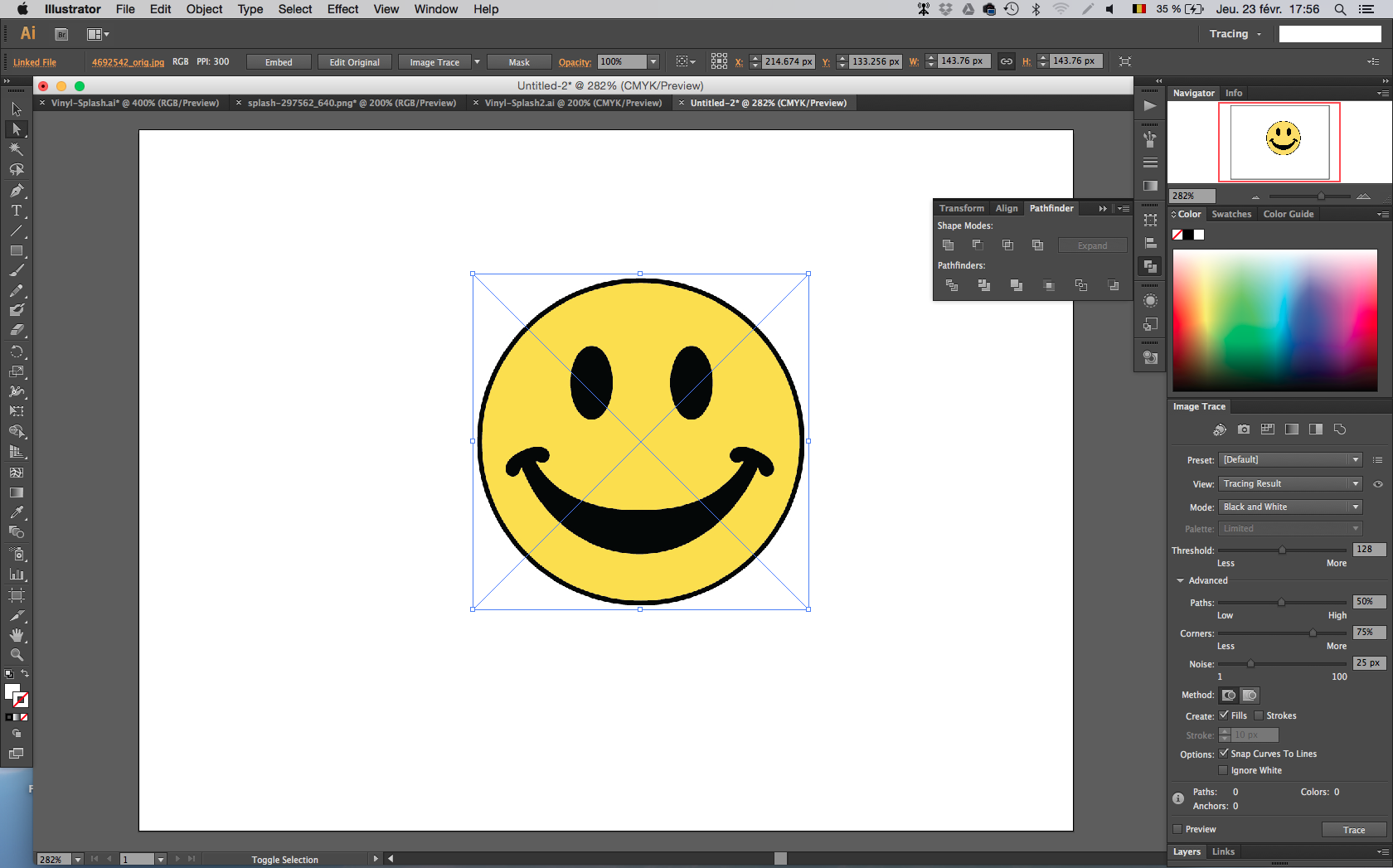
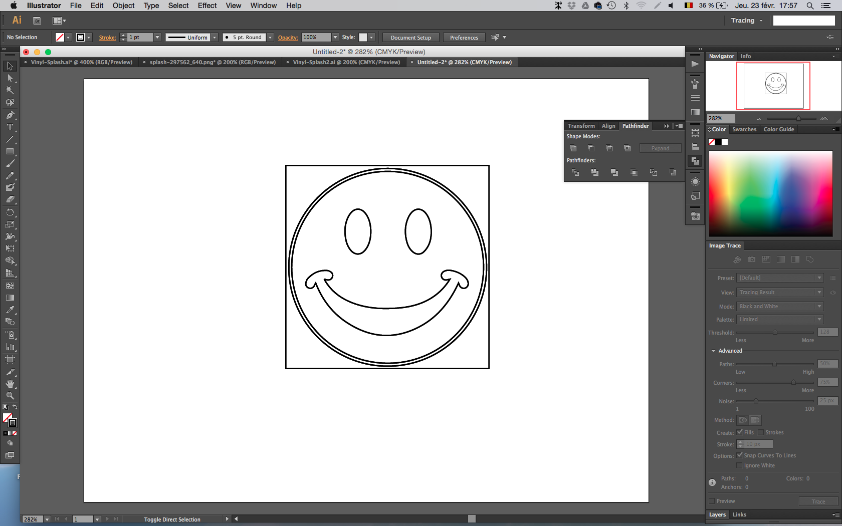
I clicked on the "tracing" button in the right upper corner and ticked the preview box.
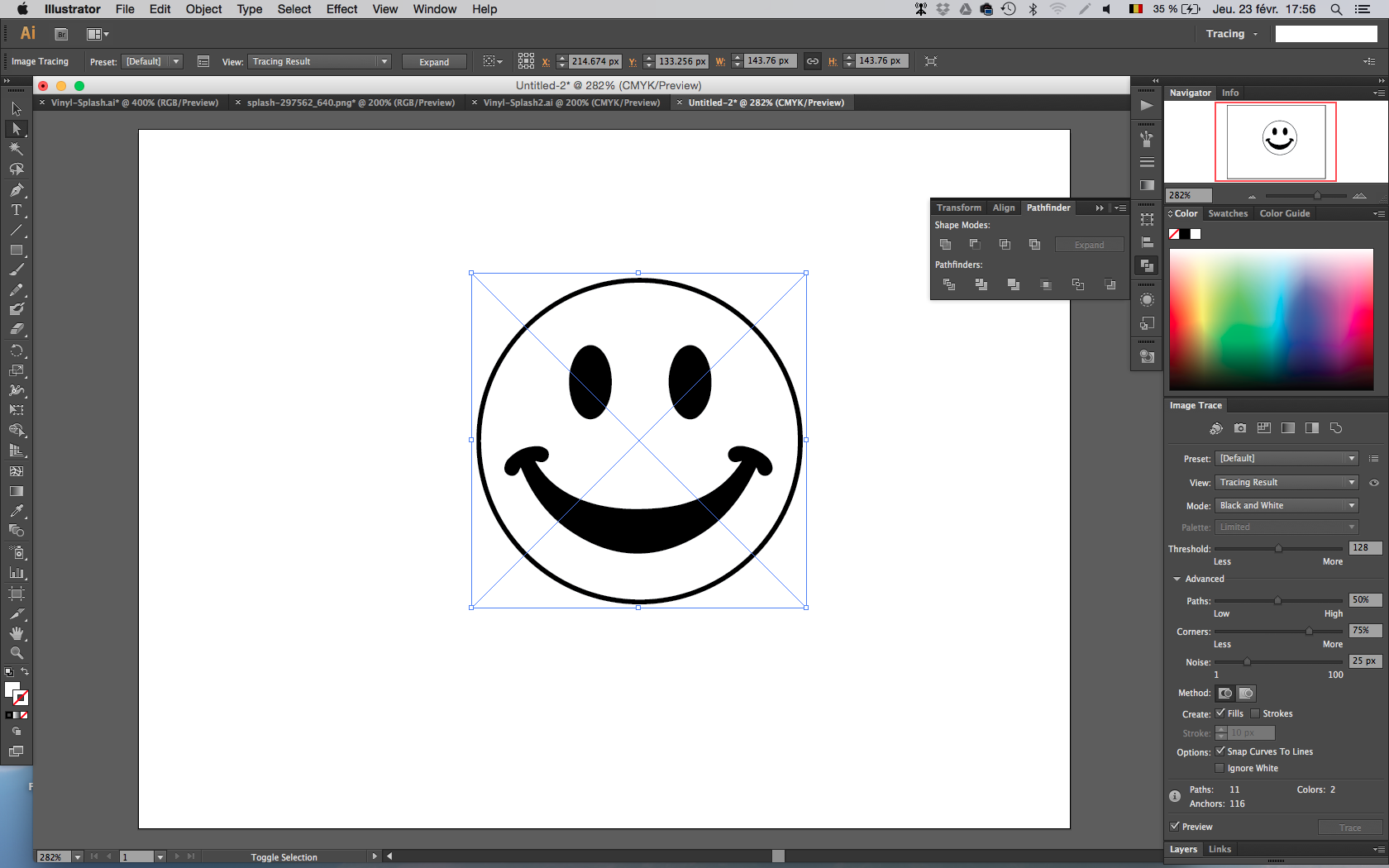
To vectorize the outline:
Object -> Image trace -> Expand
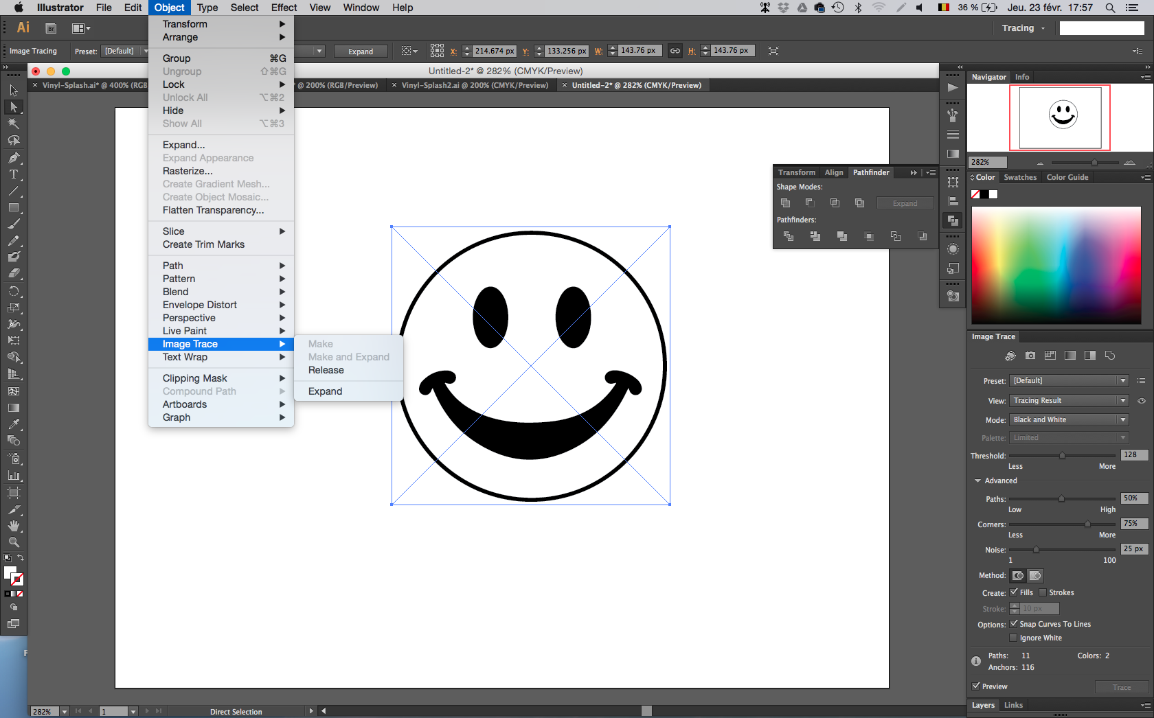
Here is the result.
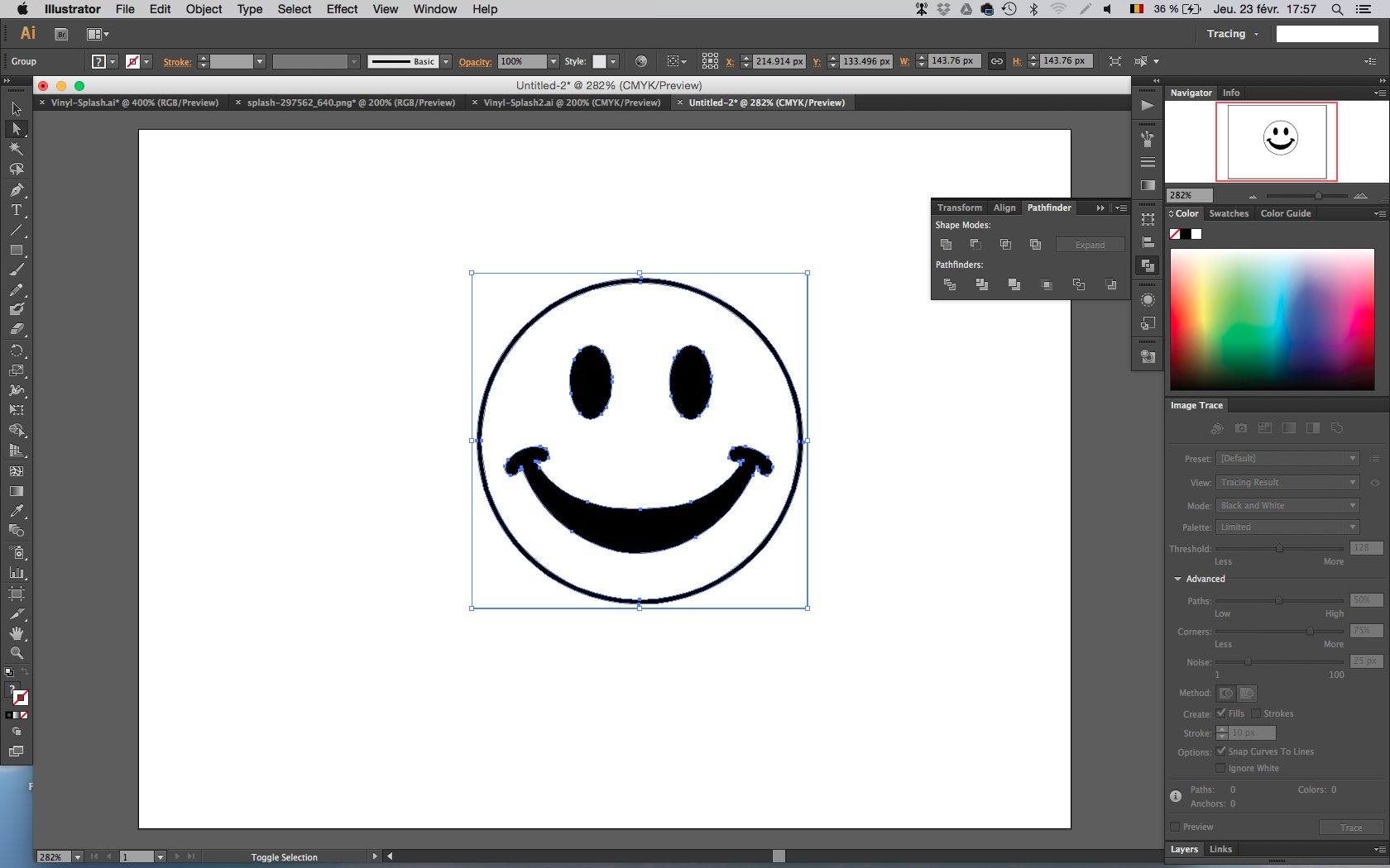
Now change the stroke and unfill the different parts.
Let's do the same with the splash.
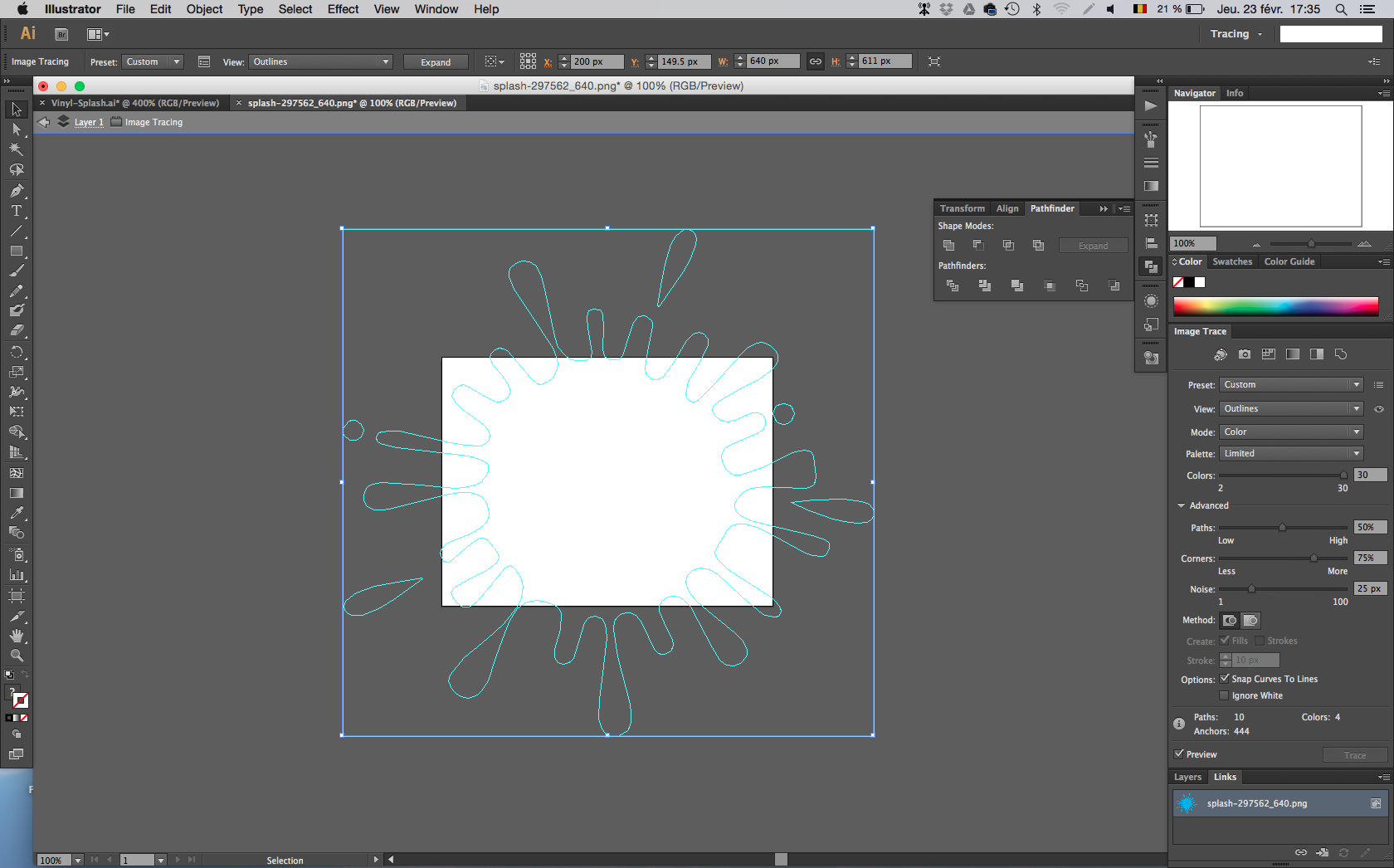
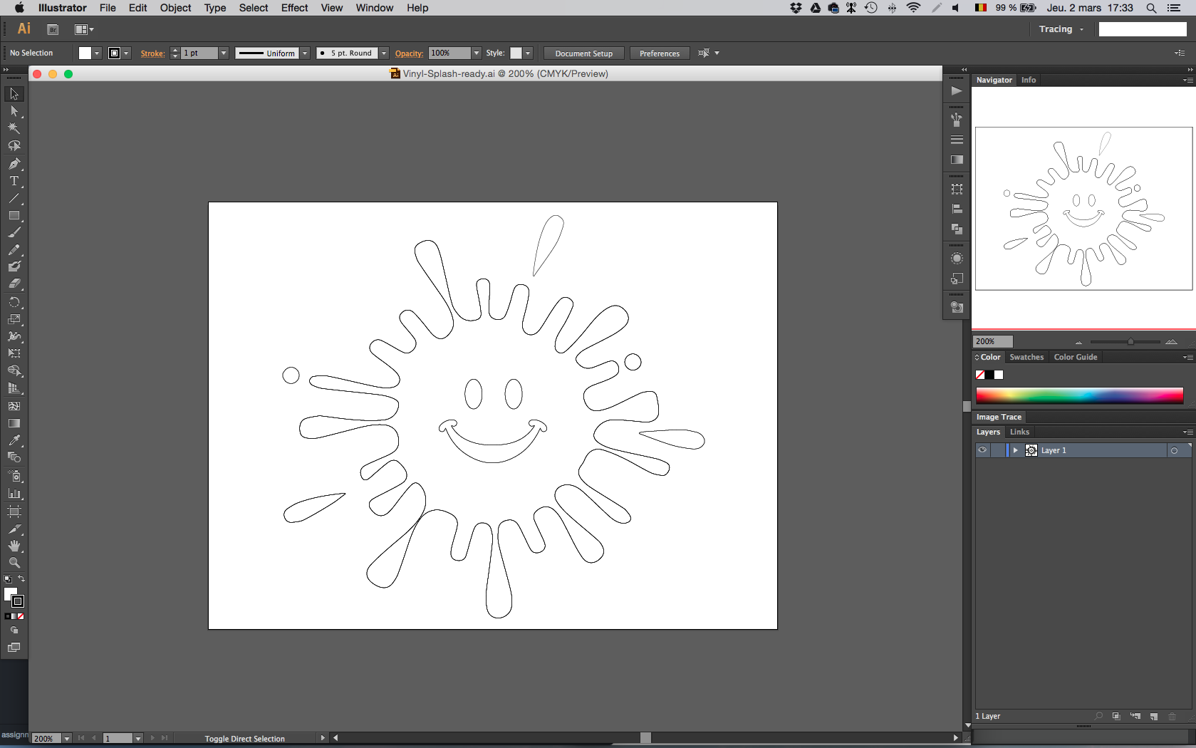
And combine them. The file is ready to be cut.
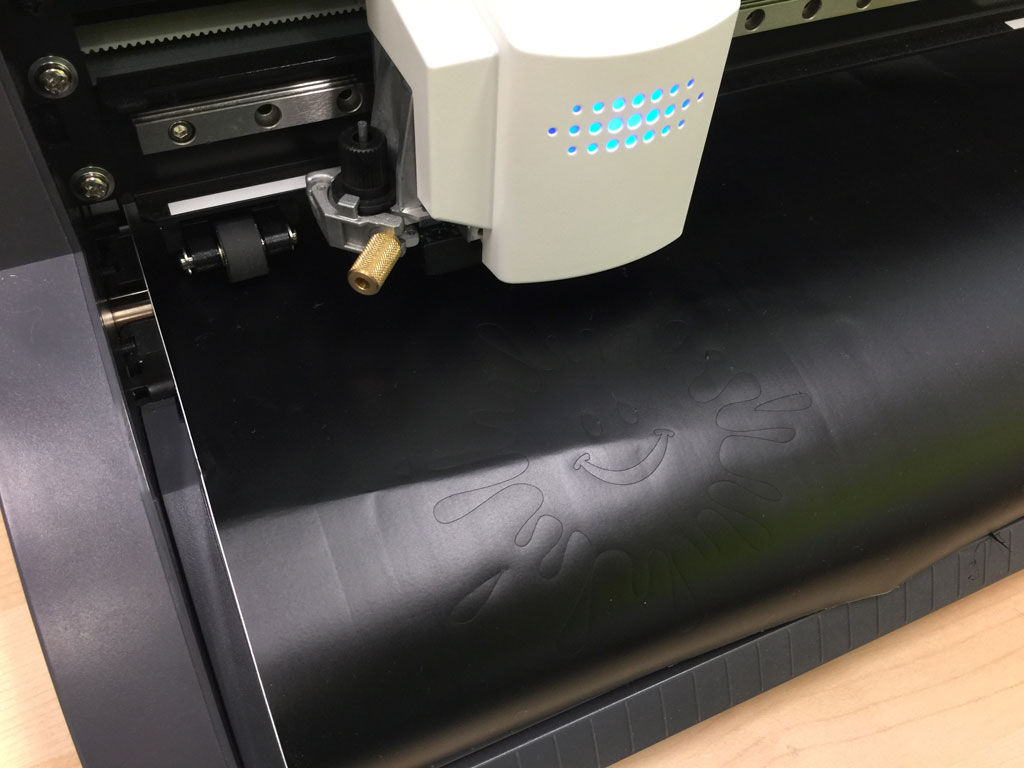
Cutting with the vinyl cutter
To cut the drawing I made in illustrator, Michele tutored me on the machine.
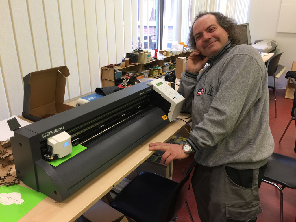
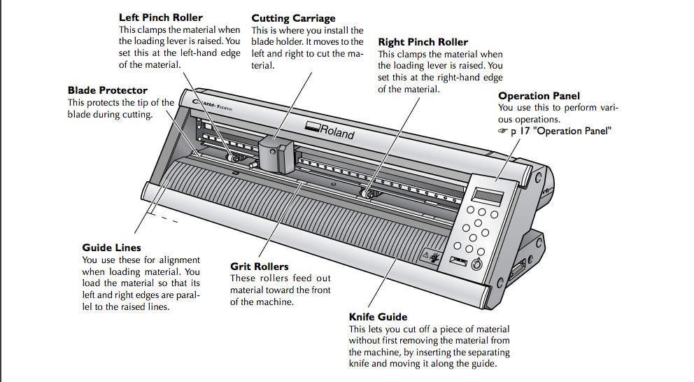
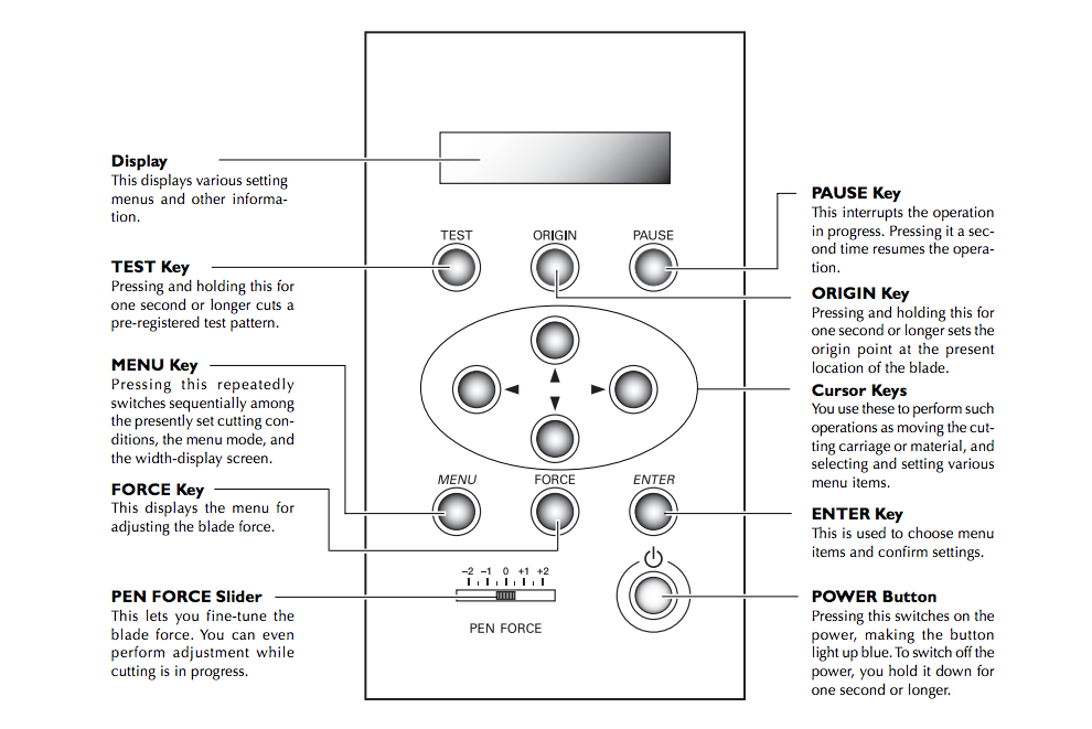
Here are some useful description of the machine and the command panel that comes from the online manual. There is also a good tutorial from the Fabacademy here and another one here on how to use the machine.
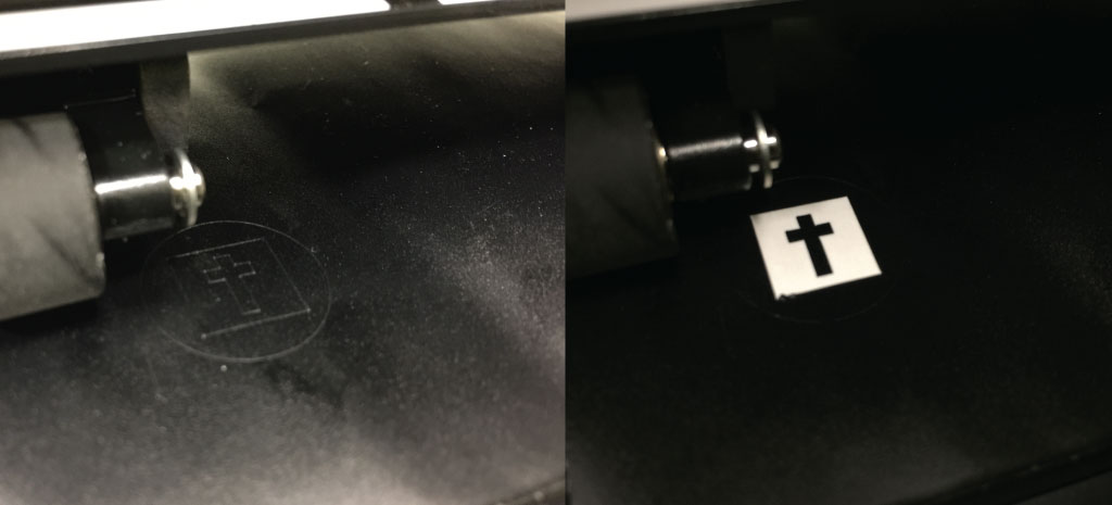
I made some tests to define the best value for the blade force. It has to be enough to cut the upper layer of vinyl but not the support below.
 I then made the cut and it failed, I haven't thought that overlapping lines would make a problem while cutting.
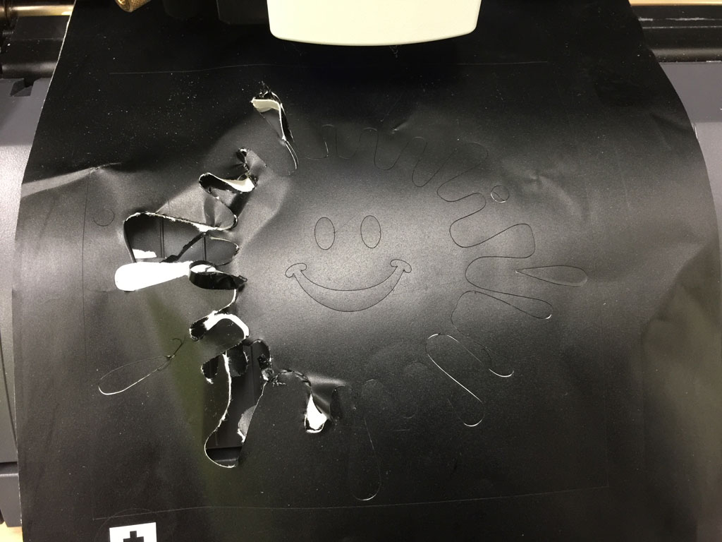
From there, I fixed the overlapping lines by separating them in the illustrator file and I decreased the cutting force of the vinyl cutter to 90gf. And it was a success.
Transfer of the vinyl part
For this part, I followed this tutorial
(1) I removed the unwanted adhesive vinyl from the support sheet. (2) Then I peeled the transfer tape that I laid over the vinyl part that I wanted to transfer. (3) I removed all the bubbles and (4) I peeled the transfer tape with the vinyl part that I wanted to transfer.
I transferred the vinyl part on the back of my computer. (1) I sticked the transfer tape on the surface of my computer and removed the bubbles. (2) Finally, I carefully removed the transfer tape leaving the vinyl part sticked to my computer.
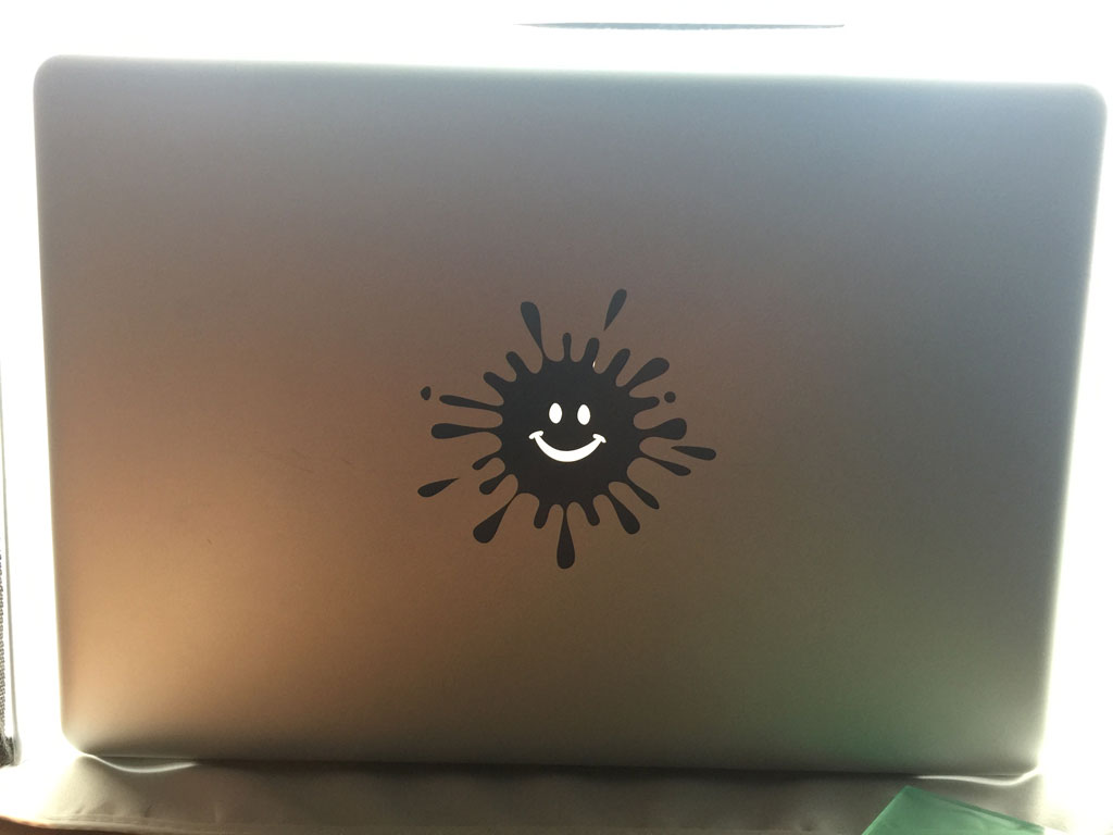
And here is the result.
It is even glowing in the dark.