Week 4 - Electronic production
- Optionally, make your own FTDI cable.
- DIY CNC milling machine
- UV lamp
- Soldering iron
- Multimeter
Softwares :
- Autodesk Eagle a PCB design software
- PCB-GCode Plugin for Eagle that allows you to generate Gcode to print, engrave or mill a PCB.
- GIMP
- Corel Draw
- Homebrew a package management software simplifying the installation of software on mac OS.
- Crosspack AVR a development environment for Atmel's AVR Microcontrollers.
- Avrdude an open-source to program AVR processor.
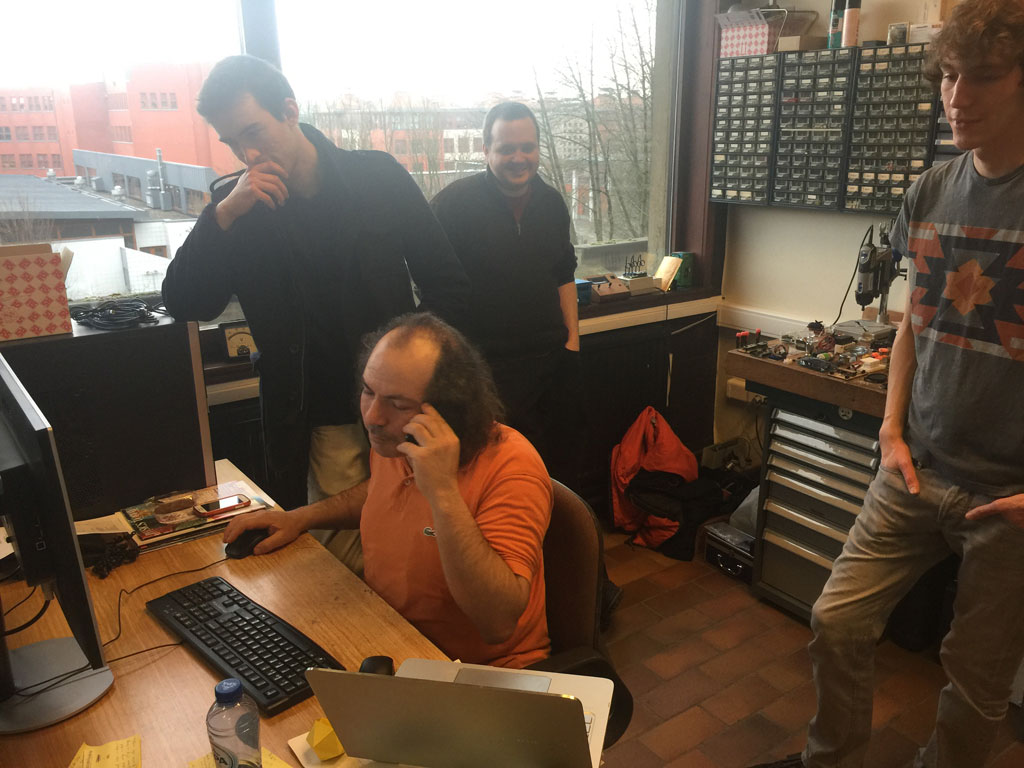
This week was a harsh week as it was a deep dive into two fields that I knew but haven't really done myself yet which are CNC milling and PCB fabrication. But most of all, that week put a lot of stress in the team which we had to manage. What is important is to make the week project until the end, seeing and "feeling" all the steps! I have learned two techniques to print the circuit: CNC milling and chemical etching. Chemical etching is quite easy to use and I have all the equipment around me. For the CNC milling it is more complicated. As the CNC machine is on another floor of my building and is operated by a technician. It was hard to stay in the control of the process. But I think this is feasible. We are thinking of buying a small CNC milling machine that would allow us to ease the CNC milling workflow. The other members of the team could make their big CNC milling machine at the Fablab ULB to mill small circuits. I had no real problem with the soldering of the components although they are really tiny and you have to be really precise and patient. It's a craft art ! I could basically program the ISP programmer but I feel that I will have to come back to that later to really understand it in more depth and be able to do more with that in the future.
As a group, the incredible part is the strategy that we used to solve the CNC milling problem when we were facing it at the end of the week. We divided in small groups and used completely different strategies. Some pushed on the CNC milling and spent the night on it and others chose and tested other etching and milling methods. At the end, we discovered that we have 8 to 10 different ISP programmers that are all working !!!
Some definitions
The electonic production week was a deep dive in lots of unknown for me. It is a week that I was apprehending.
Electronic
| Term | Definition |
|---|---|
| PCB | Printed Circuit Board |
| CNC router | Computer Numerical Control cutting or milling machine |
| G-code | a common numerical control programming language for automated machines. |
| FabISP | in-system programmer for AVR microcontrollers, designed for production within a FabLab. |
| AVR microcontroller | familly of microcontrollers developed by Atmel that use on-chip flash memory to store the program. |
Let's start
There are so many design that can be made with different components and different performance. Which one to choose? We wanted to make the simpler one proposed by Neil as a start (this one) but we were missing some components. So we chose to make another one with the ATTINY44 microcontroller that we had (but we were still missing the crystals).
CNC milling - first problems...
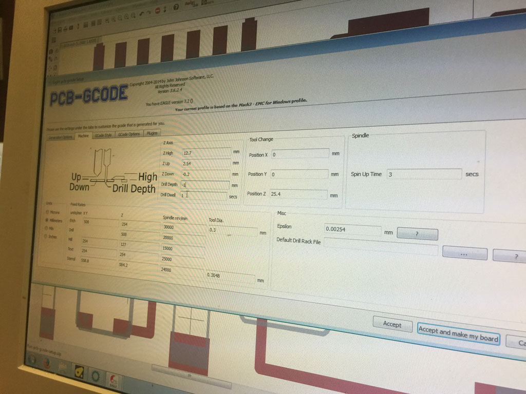
To use the DIY CNC milling machine that we have, we have to produce a G-code to control the CNC. But in the tutorials all we have are the png image files... So how to do that ? One way: redesign the design file in eagle and export it using a PCB-GCode plugin. Everybody is on the deck, helping to redesign the PCB in eagle and trying to find a way to export the Gcode that could be interpreted by the milling machine.
Exporting the PCB in gcode for the milling machine
We double-taped the PCB and placed the plate in the milling machine so it won't move during the milling.
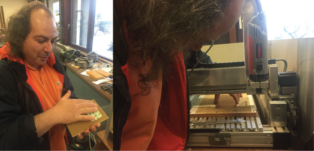
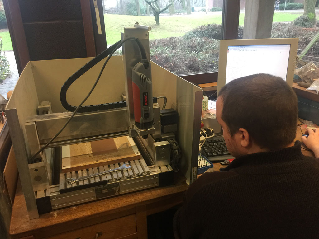
Here is the DIY CNC milling machine.
We used a 0.2 mm end mill.
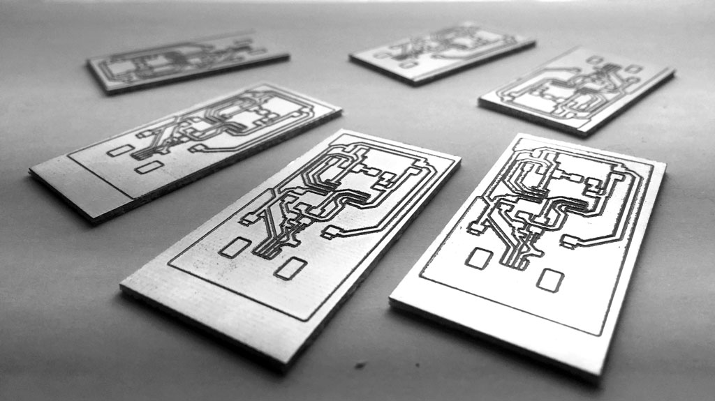
PCB milling with the CNC
Here is a movie of the CNC machine milling the PCBs.

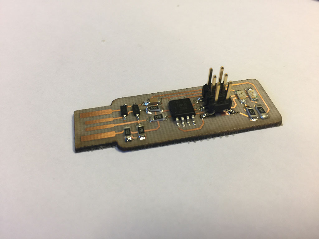
The PCBs are quite fine and we are pretty proud of them.
The team is in difficulty ! Stop and breathe !
The weekend is coming and it seems that we have not ordered all the components for the board that we chose... There are so much different designs with different components and everybody has something to say about every boards. Everybody would do the board differently... As I have never milled and make a PCB from scratch, I would like to start with something simpler. So I followed Neil's and Thomas' advice for beginners. Let's try Brian's design .
Let's prepare
It's Friday and I won't be able to work on the assignment before Tuesday, the last day of work before pushing our website for Neil's class. So I prepared everything in advance with Axel, so Tuesday would be smooth... We checked the design and ordered the Attiny45 that was missing. To try another technique, we would etch the PCB with Sodium Persulfate (it's a process that Axel use often that I really wanted to learn).
Following Roman tutorial
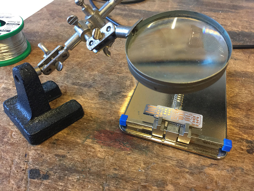
To help us with the soldering and the programming process, Roman kindly made a really helpful tutorial.
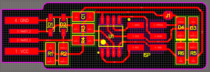
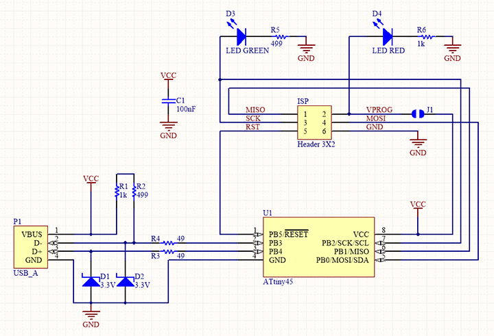
Board design
Here is the board design that I used (from this tutorial).
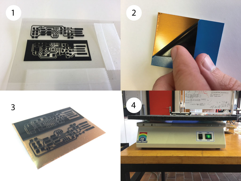
Etching the PCB
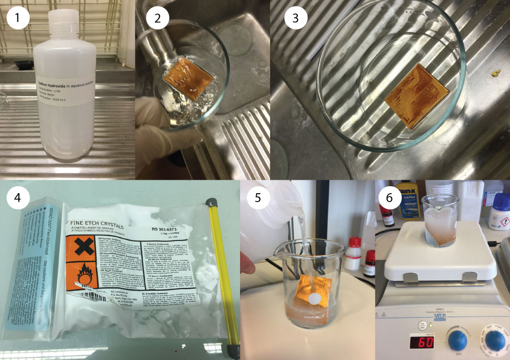
First, (1) I have printed the png file using a laser printer two times on a transparent. I superposed the two transparent to make the dark darker. (2) I used a PCB epoxy pre-sensitized resin. (3) I placed the mask on the PCB and (4) insulated it with a UV lamp for 12 minutes.
Then, (1-3) I used Sodium hydroxide (NaOH) with a concentration of 1.5wt% to remove the insulated resin. Then (4) we prepared a solution of Sodium persulfate (220 grams of this fine etch crystals with 1 liter of distilled water). Then, (5-6) I removed the copper that where the resin has been removed (about 30 minutes heating at about 60°C). Then, I removed the remaining resin using acetone. The PCBs are nearly ready.
Disposing of the chemicals, be careful !
We used 2 chemical solutions that we have to dispose away. As we are in a university, we have a procedure to follow. If you are doing that at home, you should keep the chemicals separately in a bottle and get rid of them in a public waste management facility.
The NaOH (concentration of 1.5wt%) is a corrosive base that is like a corrosive cleaning product but should be if possible put away using the chemical disposal facility (with the base). The used sodium persulfate (that is blue because of the etched copper) have to be placed in the oxydant chemical bin.
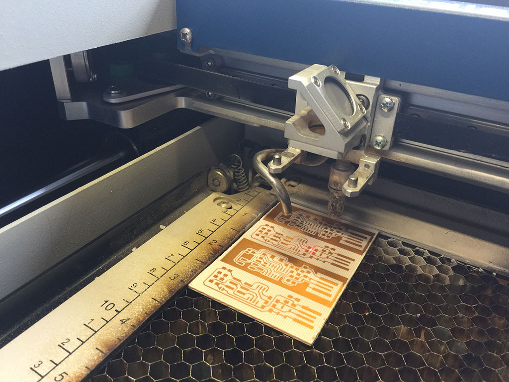
Laser cutting the PCB outline
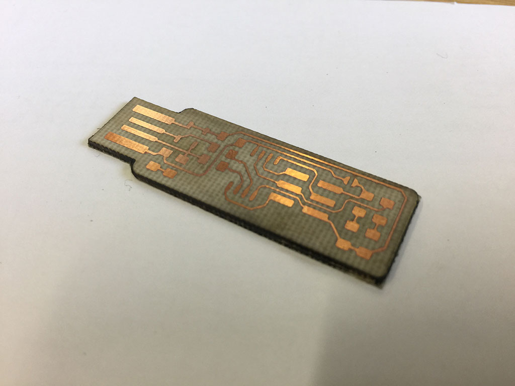
To be able to use the micro USB that we have designed we have to cut it and we chose the laser cutter to do the job. We draw a vectorial image file of the contour that we would like to cut using Corel Draw. The difficult part was to align precisely the drawing on the PCB. To do that, we tested the drawing by cutting with the power of the laser set at 0%. We followed the path that would be cut using the red laser pointer. We adjusted manually the drawing by trial and error until we are happy with the outline. Once it is ready, we cut the epoxy board setting the laser speed to 40% and the laser power to 60%. I did several path until it is nearly cut. I broke the remaining epoxy board using pliers. Then I double-taped some mylar on the other side to thicken the board that I cut using simple scissors.
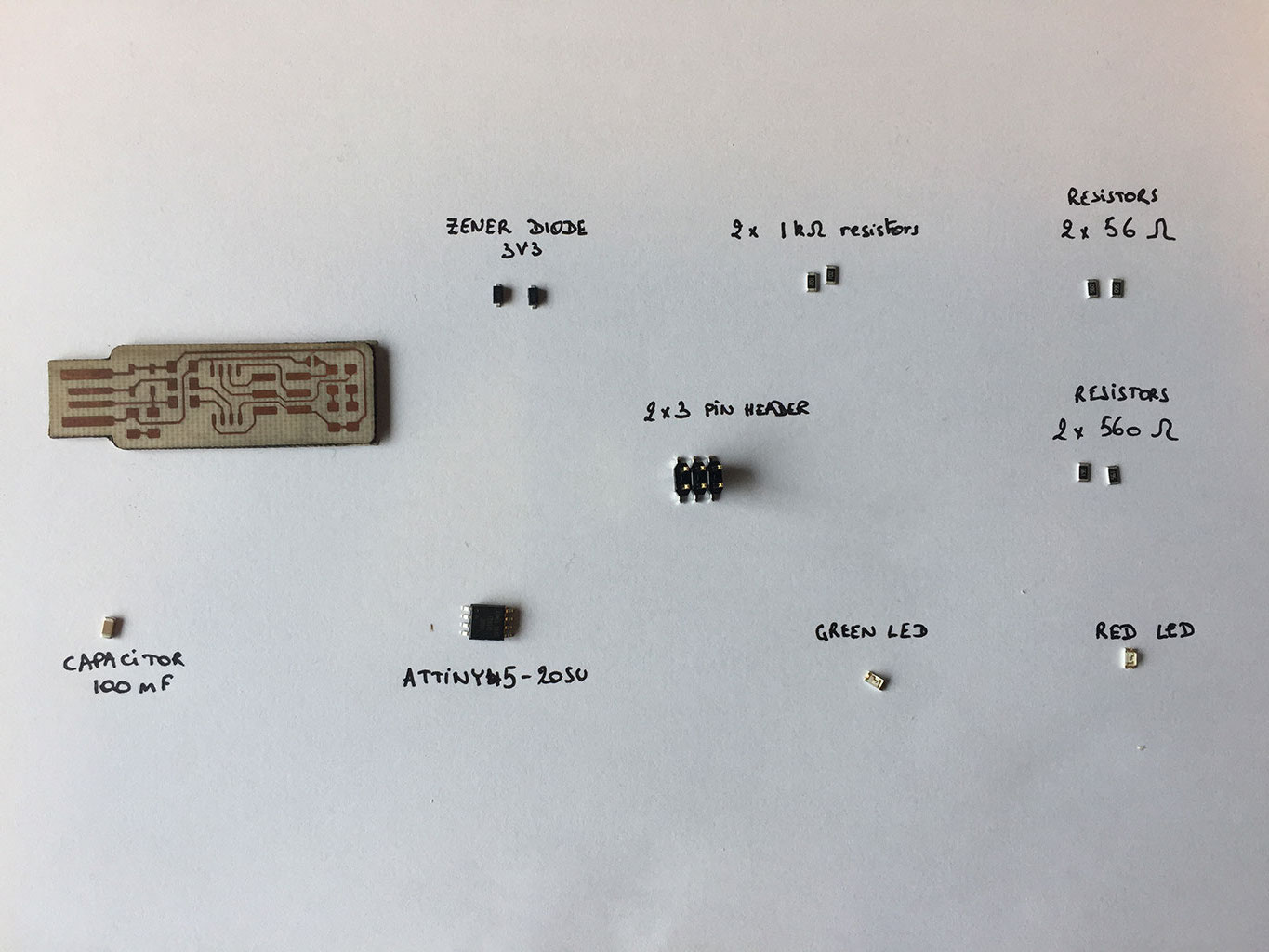
Soldering the components on the PCB

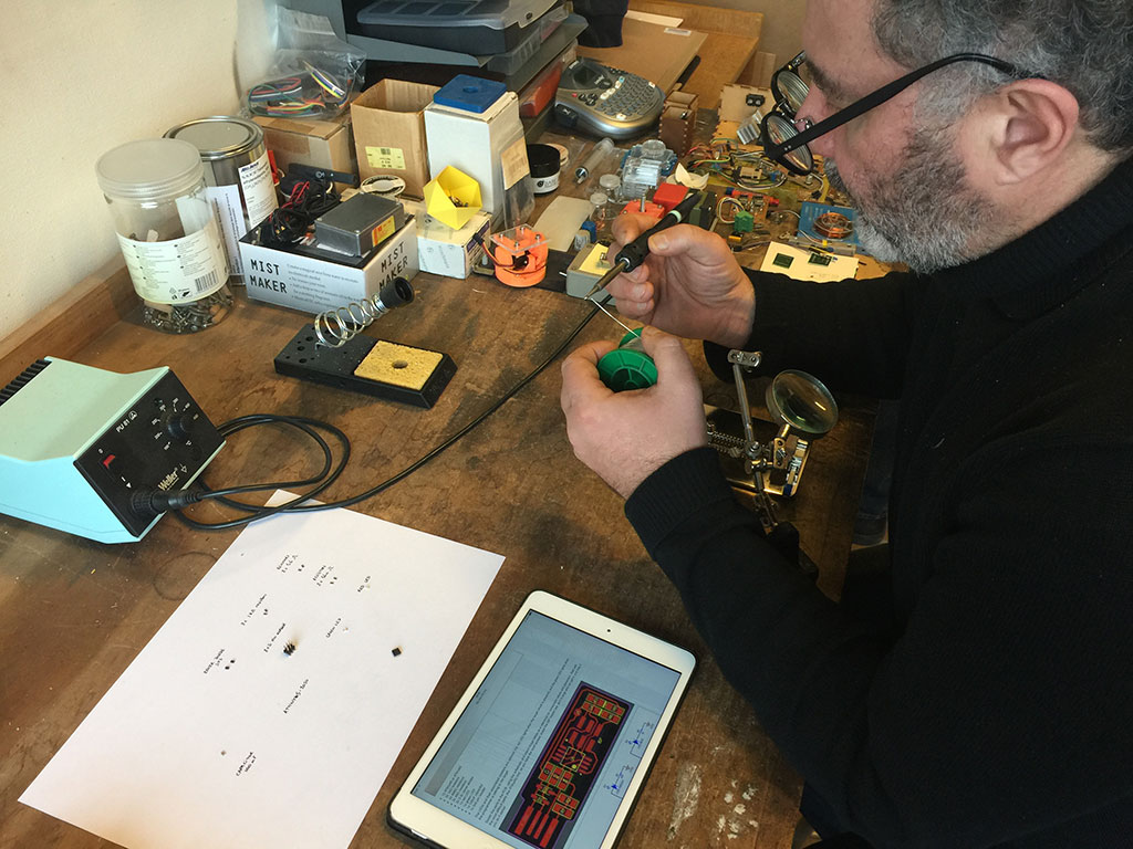


Programming the ISP programmer
Installing all the softwares required to program our chip
For this part I followed Roman tutorial that you can see up here (in video). I installed Homebrew following the homebrew website . Then I installed Avrdude which is a command-line tool that allow reading, writing and manipulating AVR processors. The arduino IDE use avrdude under the hood when it programs a board. So, if Arduino is already installed, AVRDUDE should also be installed. Finally, I installed Crosspack AVR which is a development environment for Atmel's AVR microcontrollers. To do all that, I opened a terminal and typed the following command line:
                    $ brew install avrdude

                    $ brew tap osx-cross/avr

                    $ brew install avr-libc

                    $ brew search avr

                    $ brew update
Compiling and uploading the firmware on the ISP programmer
For that part, I connected the my commercial ISP programmer to the board I just made. Then, I followed the procedure on the page Building the FabTinyISP.
I thus downloaded the firmware source code and unzipped it. Here is the folder:

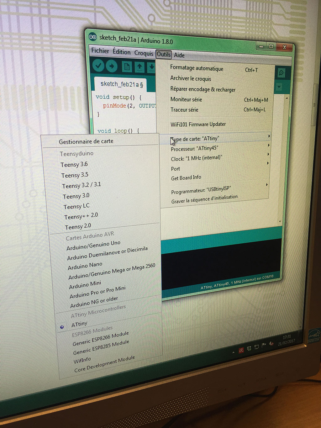
I then opened the makefile file in a text editor to verify and set all the parameters required to program my ISP. I particularly paid attention to the line:
                MCU = attiny45
                PROGRAMMER ?= usbtiny
Here is the makefile file:
I then came back to the terminal for the unzipped folder I did the following procedure.
To remove all the auto generated files and clean the folder:
$ make clean
To generate a .hex file:
$ make
Here are the generated files:

To upload the program (.hex file) on the microcontroller via the ISP programmer:
$ make flash
To program the fuses on the microcontroller chip.
$ make fuses
To blow the reset fuse.
$ make rstdisbl
Here is what we get in the terminal when using the command line here above.
Testing the ISP programmer
Ok, the installation seems to have worked. Let's connect it to the USB port of the computer.

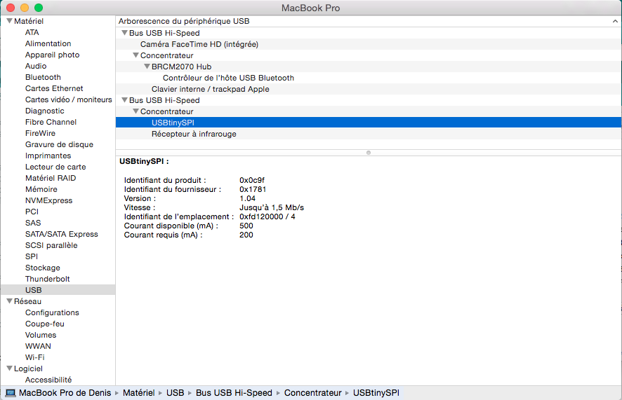
And the ISP is well recognised by the computer (see below). Yeah !!
Troubleshooting
The first version of the fabISP was not working all the times. Sometimes, I could upload succesfully a program to it, sometimes not. Avrdude was saying that I should check the connection. I checked visually the board and then with a multimeter and everything seemed ok. I tried to force to make and upload the firmware on the fabISP but it didn't work at the end. So, I removed the ATtiny45 chip and replaced it. Everything worked fine from there and I can use it as an ISP programmer !