Week 2 - Computer-aided design
- model (draw, render, animate, simulate, ...) a object/part of your final project in 2D and 3D software.
- Scanner : Iphone camera + scanner pro connected to my dropbox for a fast upload of the files on my computer
Softwares :
- Solidworks for creating, assembling and animating
- Scanner pro for scanning anything from book pages to blackboards.
- Draft Sight for 2D parametrical design.
- Fusion 360 for 3D parametrical design.
- VLC Media Player for reading the video files
- Dropbox for synchronizing files in the cloud and on different devices (computers, tablets, phones)
Selecting 2D and 3D modeling software
After Neil's class we were pretty stressed out with all the software he has showed us. After that meeting in our Fablab in Brussels, we had a pretty interesting discussion with Victor, David, Jeremy and Michele. Everybody shared their skills and acted very differently. That's very interesting to see how different everyone of us is facing the same challenge. Victor was mastering vectorworks when he was young and needed to get his hands dirty again. David knew a lot of pretty interesting software: Rhino, Grasshoper, Design Spark, Mechanical software, fusion and so much more that I don't remember. Jeremy, always ahead, did 5 hours of tutorial the day after Neil's class (after his regular work). Regarding me, I already knew photoshop, illustrator, Coreldraw for 2D designs and Solidworks for 3D designs. Although, 2D softwares can be pretty intuitive. 3D softwares such as Solidworks are not ! I remembered the learning curve, when I was at MIT, was pretty long but once you understand how it works it is really quick to build anything. And there is a need to be elegant in the way we design ! An excellent design is so useful when you want to use the parametric functionality. Then during the end of the week, with Axel the fabmanager of my lab, we had a great interaction on 3D design. Pretty smooth and efficient ! After 3 or 4 years without using Solidworks, I was expecting that it would be a bit difficult to get back on my feet but at the end it was pretty smooth. Thanks to Axel who did a great job on tutoring me ).
Using Solidworks for 3D design
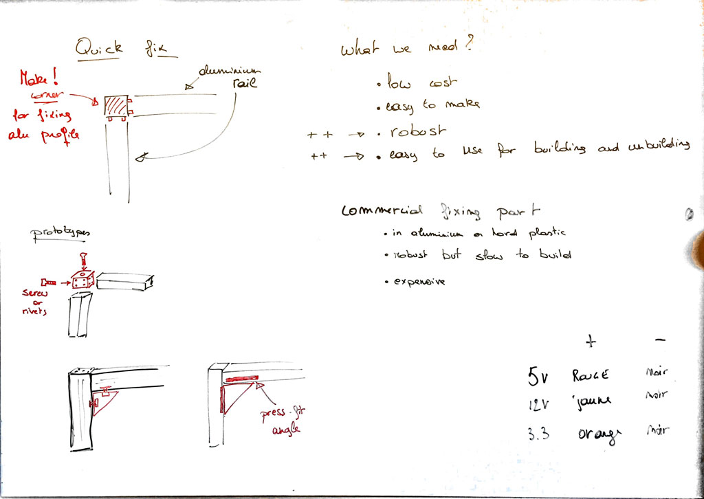
To get into my final project, I needed to start by the very beginning and understand what is a good design for the construction building blocks. I looked at commercial mechanical parts that are usually used in scientific labs and try to understand the reason why they are design like that and how to improve it for my purpose. Here is a photo of my white board.
Creating a 3D design sketch
For the construction kit we will use commercial aluminum bars such on the picture here below. I started by designing a rail. The 3D design files of the commercial rails can be obtained on the Thorlabs website (here). So I could open it in Solidworks. Solidworks tried to recognize the functions that were used to make this piece but it did not really work. So I decided to reconstruct the rail. To do that, I have rotated the 3D sketch to see the cross section. Then, I started a new sketch and traced the contour of the cross section (base) of the rail using the line and curve tools. After the base was made, I hid the commercial sketch and extrude the base on a length of about 10 cm. The first 3D rail design was made.
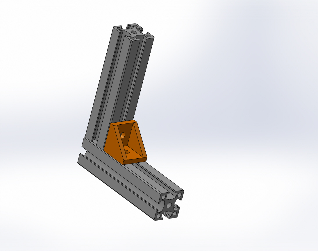
Assembling 3D parts
To connect 2 rails at an angle of 90° we will use a 3D printed flat angle bracket which 3D file can be found in the source files at the top of the page. So, I have 3 objects that I would like to assemble in Solidworks. To do that, I've created a new assembly project in Solidworks and imported the 3D files of two rails and the flat angle bracket. It was pretty easy to assemble them, just by constraining and aligning the faces of each pieces to get the construction here below.
Animating the 3D design
Now that the assembly is made. I wanted to animate the construction of the final object. I followed a tutorial online which helped me to create an exploded view of the construction and animate it to reconstruct it (Link for the tutorial in french can be found here ). Once the animation was made I exported it in an ".avi" file and opened it using VLC media player. After that I have uploaded it on my youtube account and created an inline frame to embed the video on my website down here.
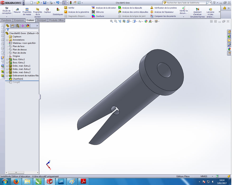
Designing a dowel in 3D
In order to test another way for fixing the rails at an angle of 90°, I have imagined a system that needs a dowel for a M3 screw. This dowel has to fit in the 5mm diameter hole in the center of the rail (along its long axis). I will then 3D print it and I would have to tread mill the top part of the dowel to allow the screw to get in. The bottom part of the dowel expands when the screw gets in further. The goal of this dowel is that, if the screw is already partially screwed, it is really fast to tight and untight the system screw+dowel in the hole.
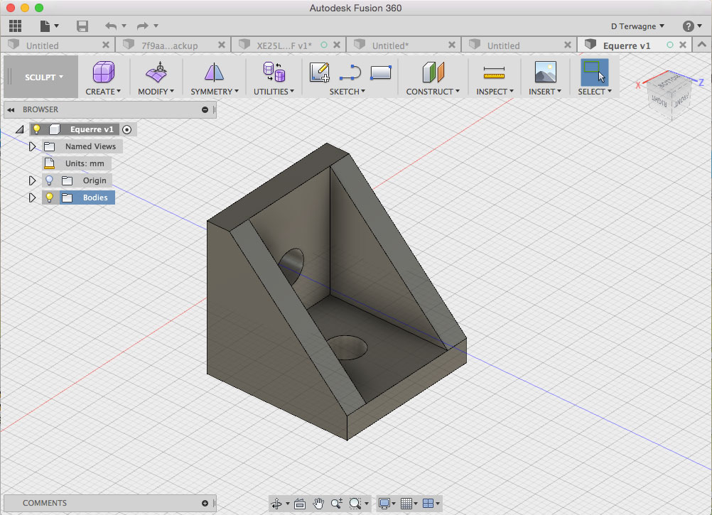
Next steps - Fusion 360 and DraftSight
I have installed on my computer Fusion 360 from Autodesk for 3D design and DraftSight for 2D design. After playing around a little bit with these softwares they seem pretty useful. I'm sure I will use them in the very next future. The nice thing about both of these software is that they exist for the mac version. Solidworks only exist for computer with windows OS. Here is a screenshot of the flat angle bracket in Fusion 360 ready to be printed.
2D design softwares
updated on July 4, 2017
All along the Fabacademy, I've used 2D design softwares such as Illustrator and Corel Draw. Details on how I used Illustrator to make a press fit lamp and a vinyl sticker can be found here, on week 3.