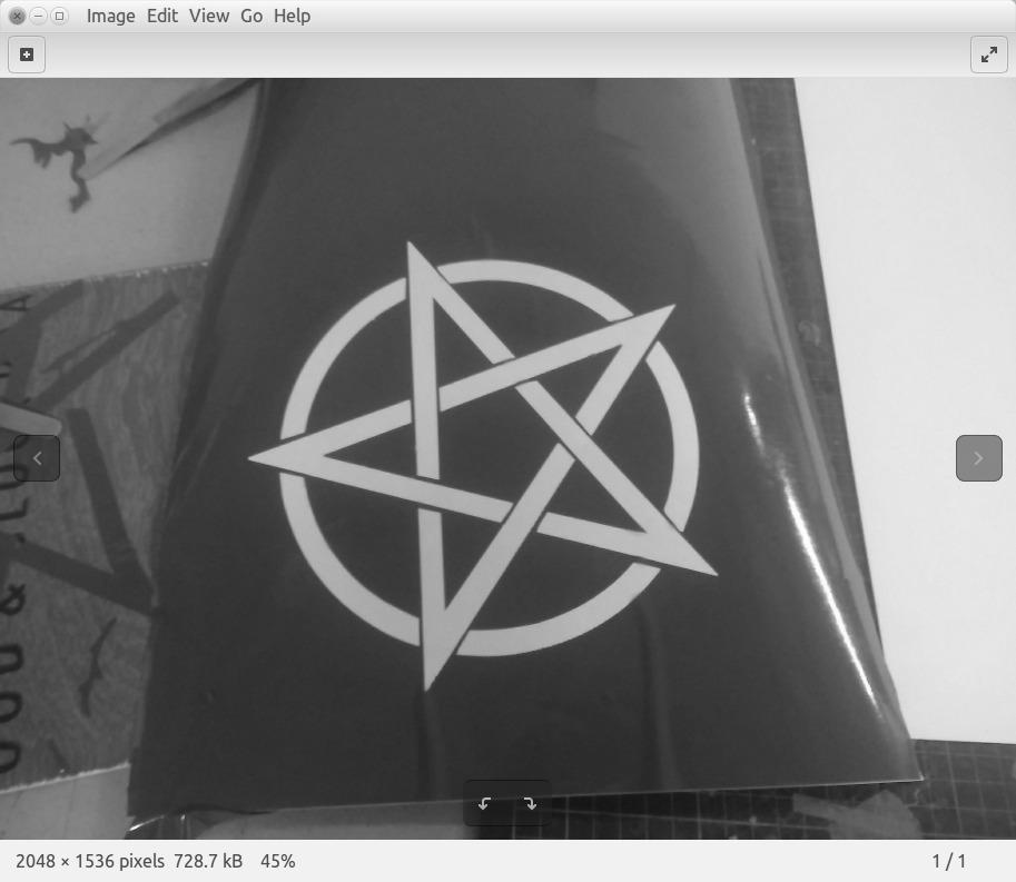
Read through the official user's manual of the Vinyl cutter
I prefer the official manual by default, because I find the 'technical writing' in these sorts of literature quite interesting
Pick a CAD software to make a drawing to vinyl cut
I chose to install 'LibreCAD', as I haven't tried it yet and wanted to acquaint myself with open source alternatives and eventually contribute to the open-source community.
Installing LibreCAD and learning the basics
I installed LibreCAD with sudo apt-get install libreCAD on 'Ubuntu 16.04 LTS', and was pleasantly surprised to see that the download file size was only ~30mb
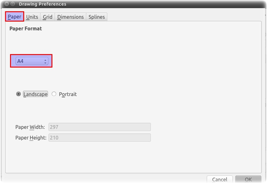
Making sure that 'Preferences' are set to one's liking
Go to "File > Preferences"
Set paper size
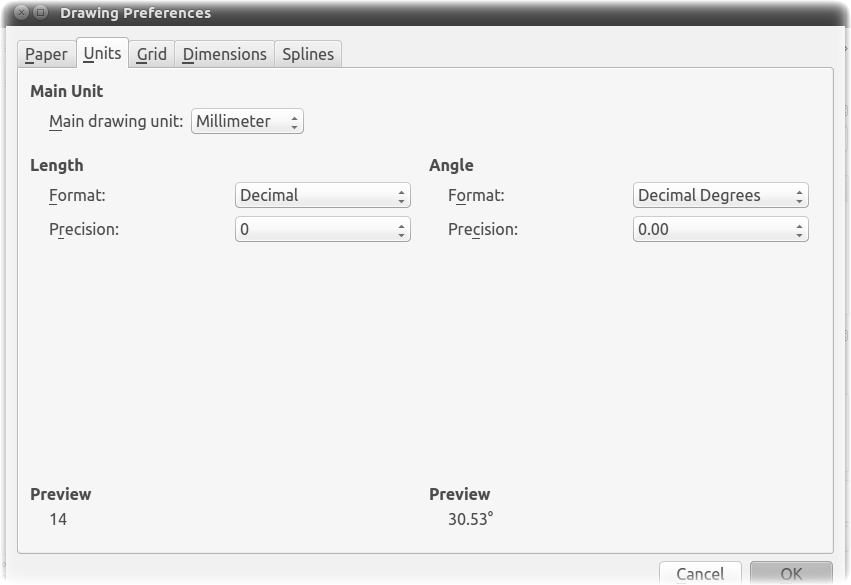
Set units
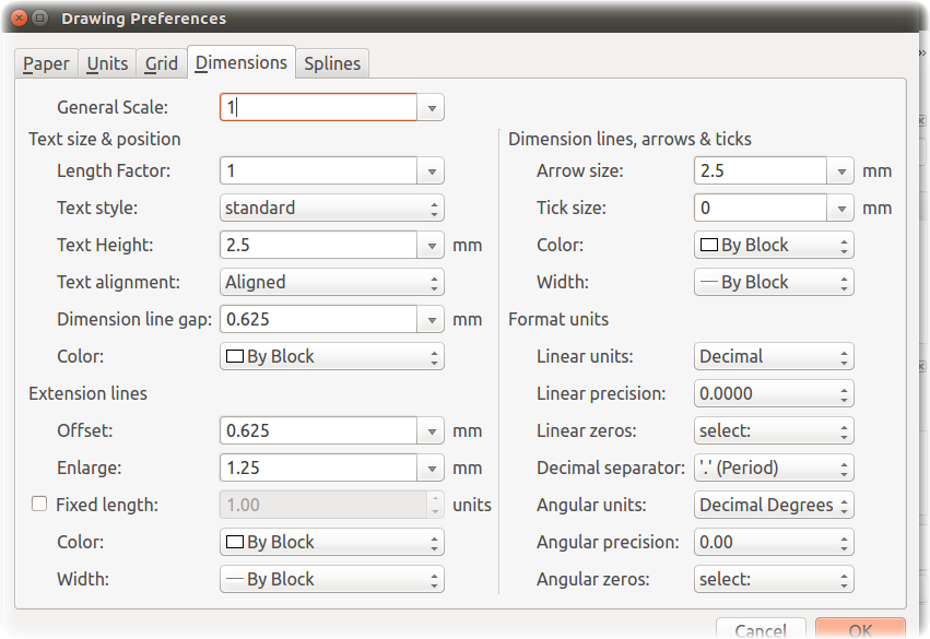
Under the 'Dimensions' tab, set the default sizes for 'text blocks'and dimension lines
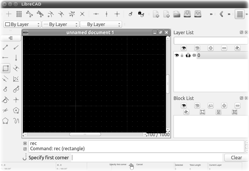
The Grid in the drawing space will adapt to the screen size and zoom level in the order of 10s. So make sure to look at the 'Grid sizing' numbers represented as XX, YY in the bottom left corner before using the Grid for drafting lines
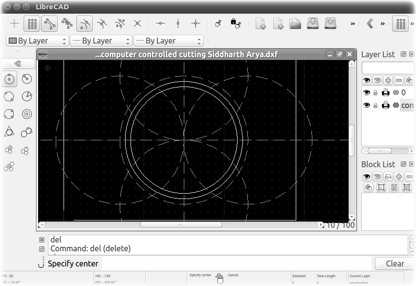
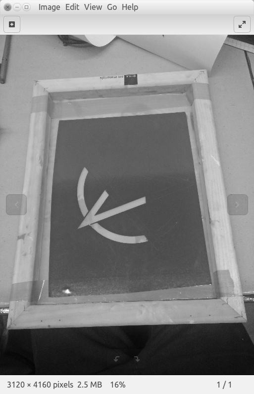
I used circles ('ci command') and lines ('li' command) in a new construction layer to develop the framework for a pentagram
Lines drawn in the construction layer are infinite in length by default, as opposed to the lines drawn, for example in layer '0'
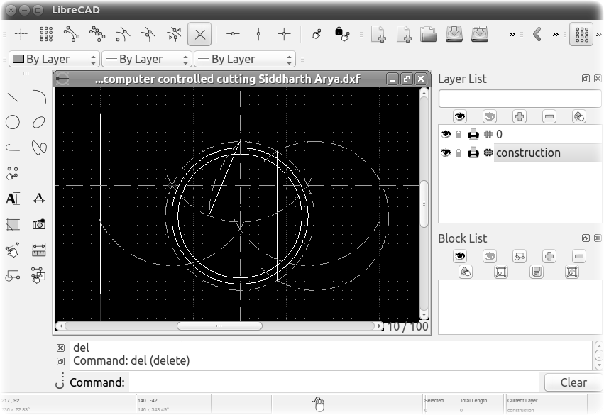
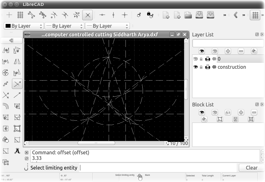
Needed more construction lines for the top 2 vertices of the pentagram
Using the command 'offset' I gave the pentagram some thickness
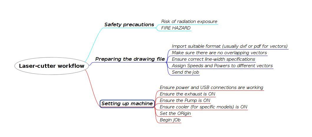
Workflow with Vinyl cutter
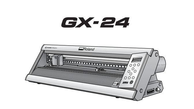
The vinyl cutter we had access to was the Roland GX-24, it was hooked up to a Windows 7 laptop running the bundled cutting software - 'CutStudio', the workflow involved the following steps.
this mind map was created with 'Freeplane'
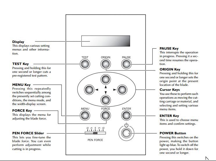
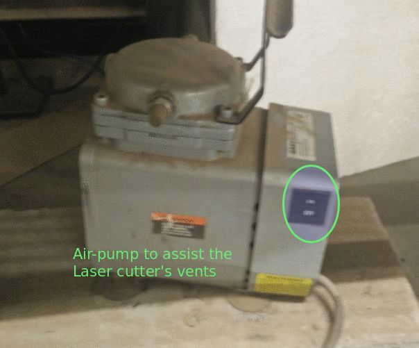
/setting up the machine
Setting up the machine involves the following
Lift the sheet holder lever
Insert sheet
a;ign sheet to markers
Close sheet lever
adjst rollers to sheet width
set origin
set pressure
specify if roll or sheet
Done
/preparing files
I've used the bundled software - CutStudio to prepare the drawing file
the formats it can export are very limited
I had to export a jpg from My CAD software and trace the outlines in CutStudio
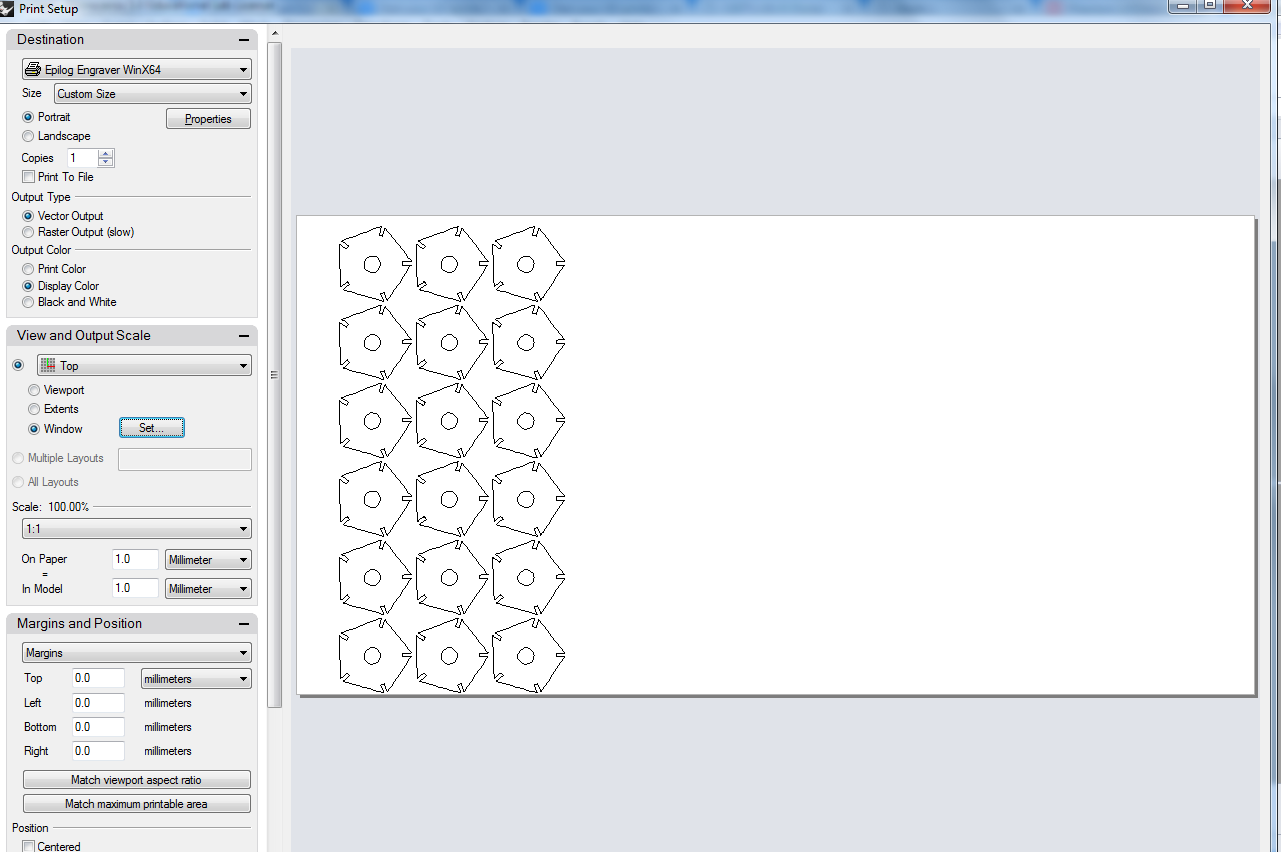
After tracing the outline, I scaled the drawing
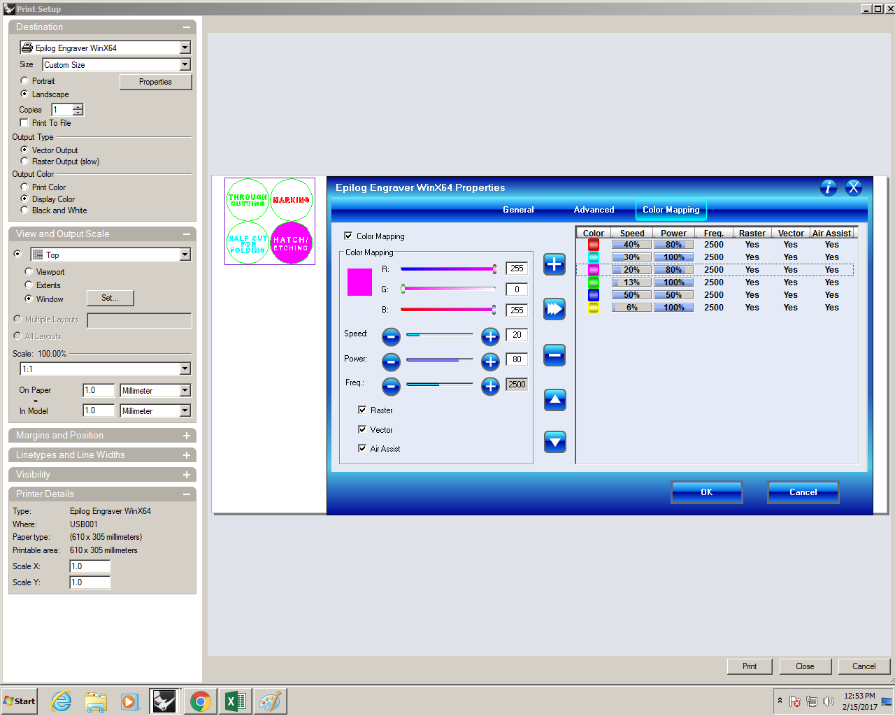
Then specified the sheet size from the 'print setup' dialog
'Print'
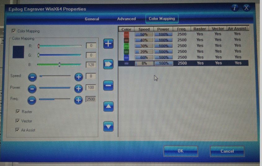
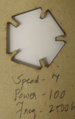
/cutting settings
THe main variable is the downwards force the blade applies on the sheet to be cut, through error and trial - i found the folllowing cutting pressure to be ideal
95 g/sm 2 (grams per centimeter square)
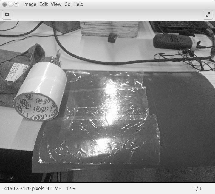
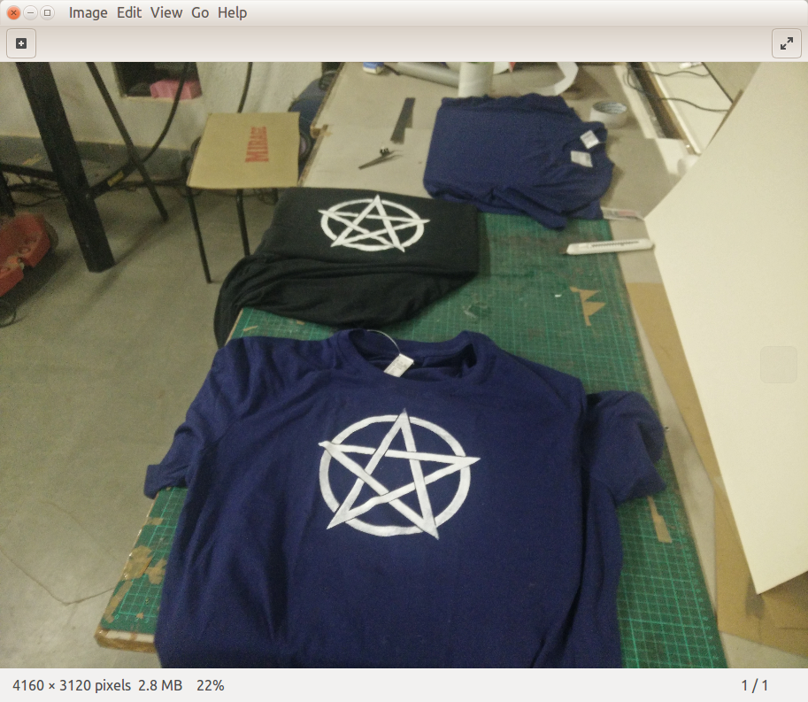
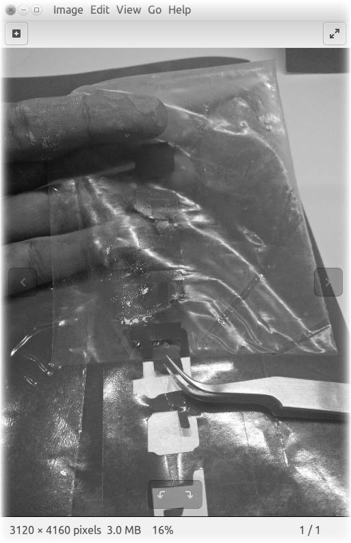
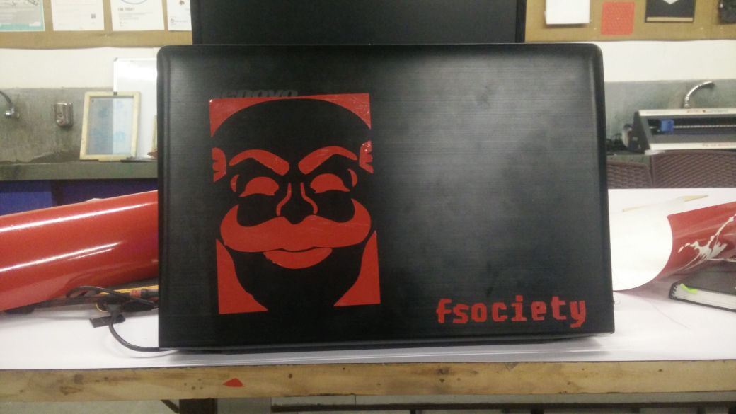
Screen printing with the above design and transfering vinyl to laptop
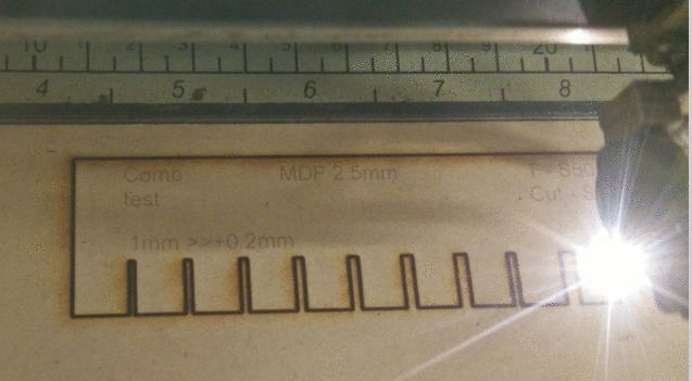
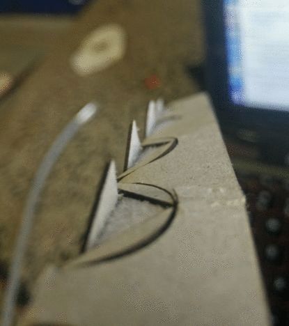
Group project - Testing the laser cutter settings and learning about kerf
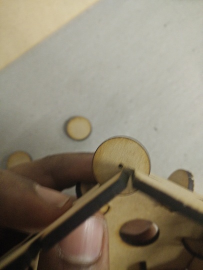
kerf traditionally is the width of the slit left by a cutting blade like a saw made when it bites into the material being cut; similarly, in laser cutting - kerf is the width of the slit burnt up by the laser.
A lot of variables determine the kerf width i presume, among them would be lens cleanliness, bed levelling and mainly the focus setting
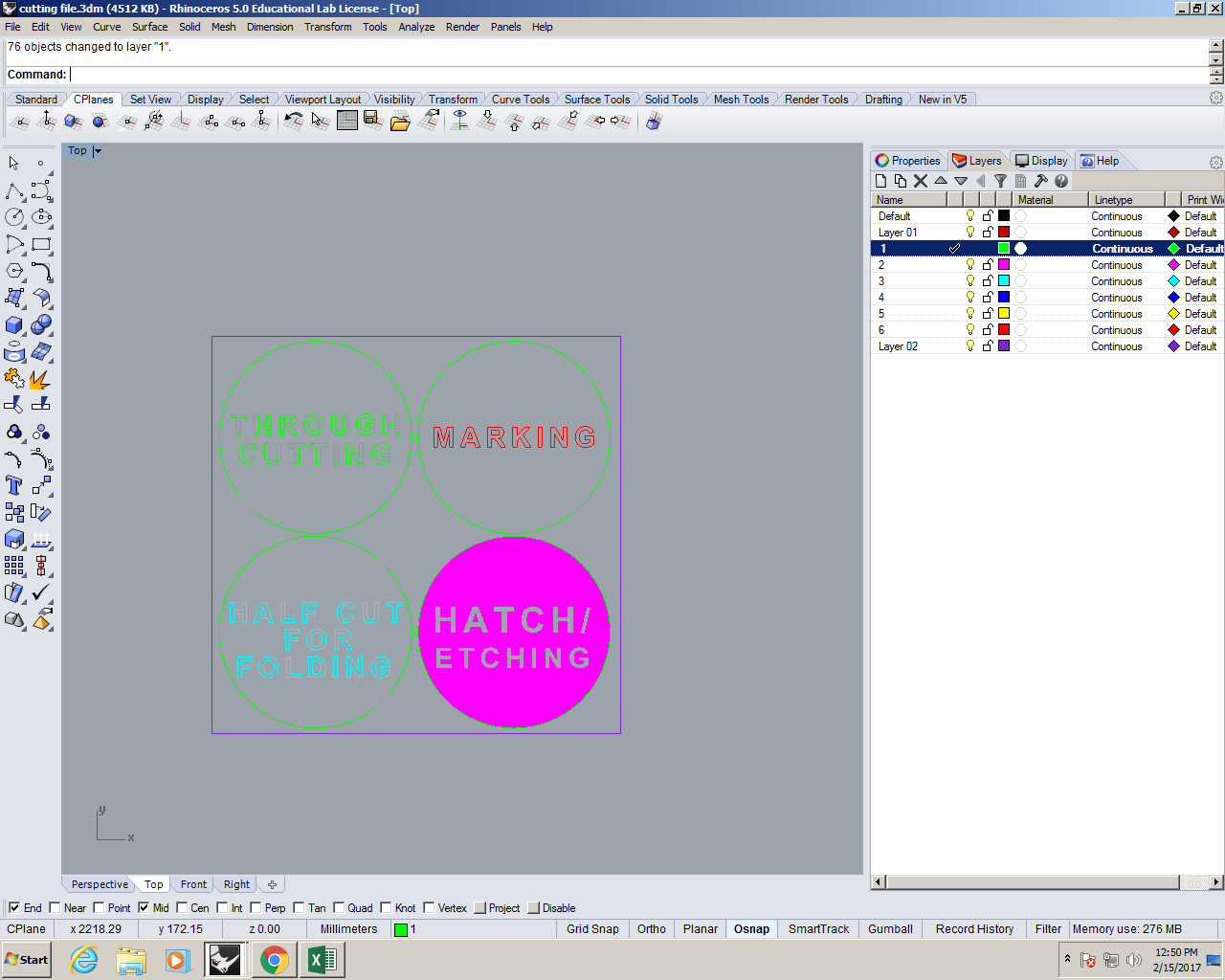
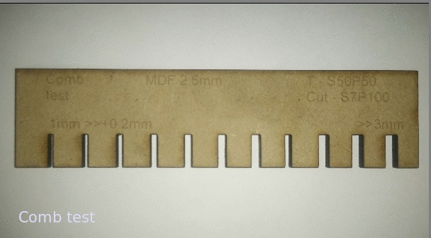
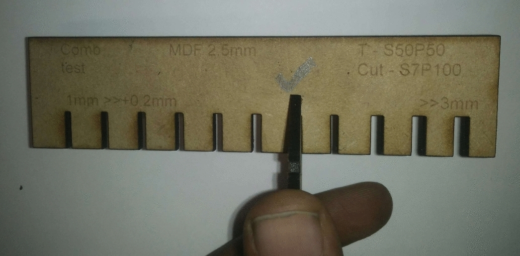
As part of the group assignment, we found out the ideal settings (Power and Speed) for 15 differnt materials like different papers, MDFs and acrylics; for four cut-types - through-cut / etching / Half-cut / MArking
We made a chart for it and displayed it in the lab.
Read through the official user's manual of the Laser cutter
I prefer the official manual by default, because I find the technical writing in these sorts of literature interesting.
Pick a CAD software to make the parametric drawing
I chose to use 'Antimony', as I haven't yet tried 'nodes and noodles' type of programmes and watching the 'Intro to Antimony' video by Matt Keeter where he models a screw driver intrigued me.
Installing Antimony and learning the basics
I installed Antimony by following the instructions in the Github pageI faced no issues while building/making? Antimony from the repo on Ubuntu 16.04 LTS'
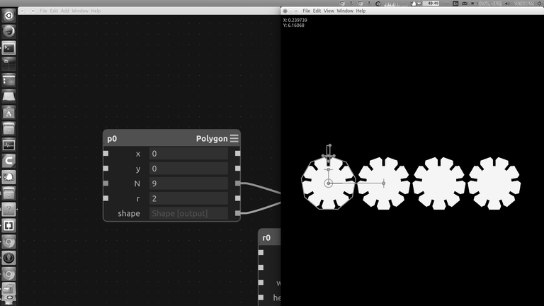
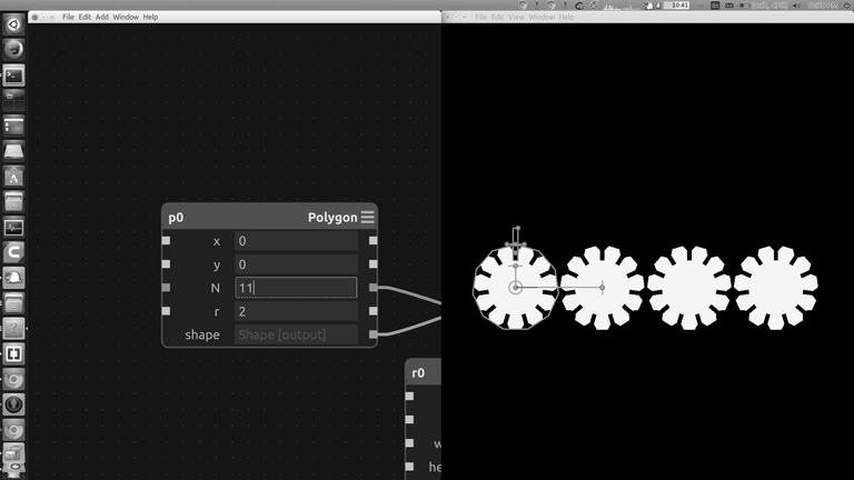
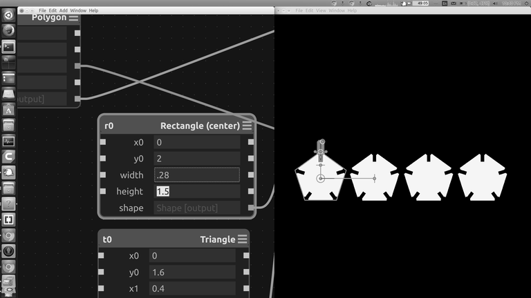
Using Antimony to make the drawing (unedited video) - Please play in '2x' speed ( ͠° ͟ʖ ͡°)
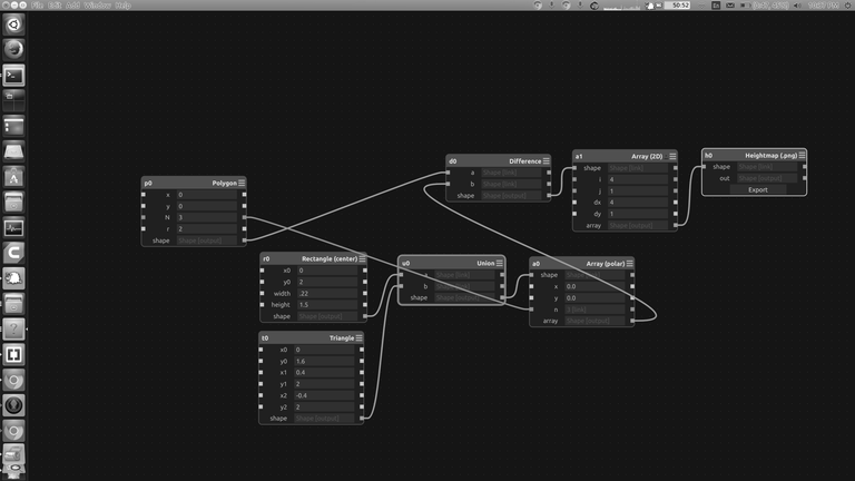
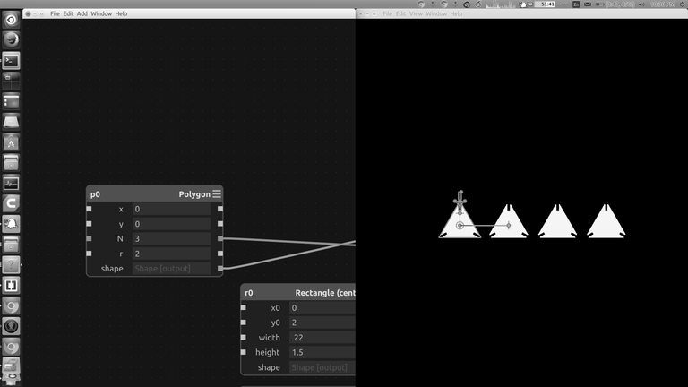
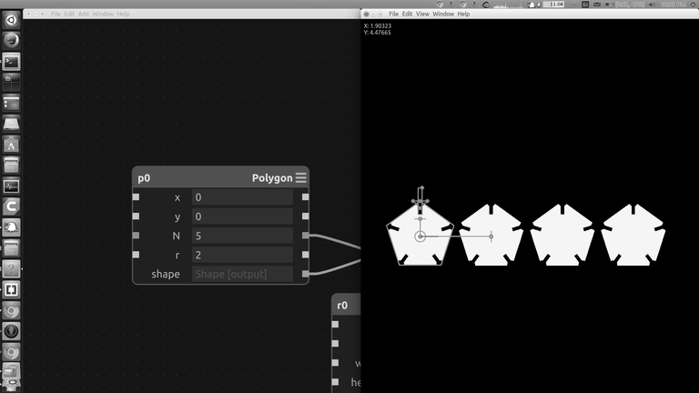
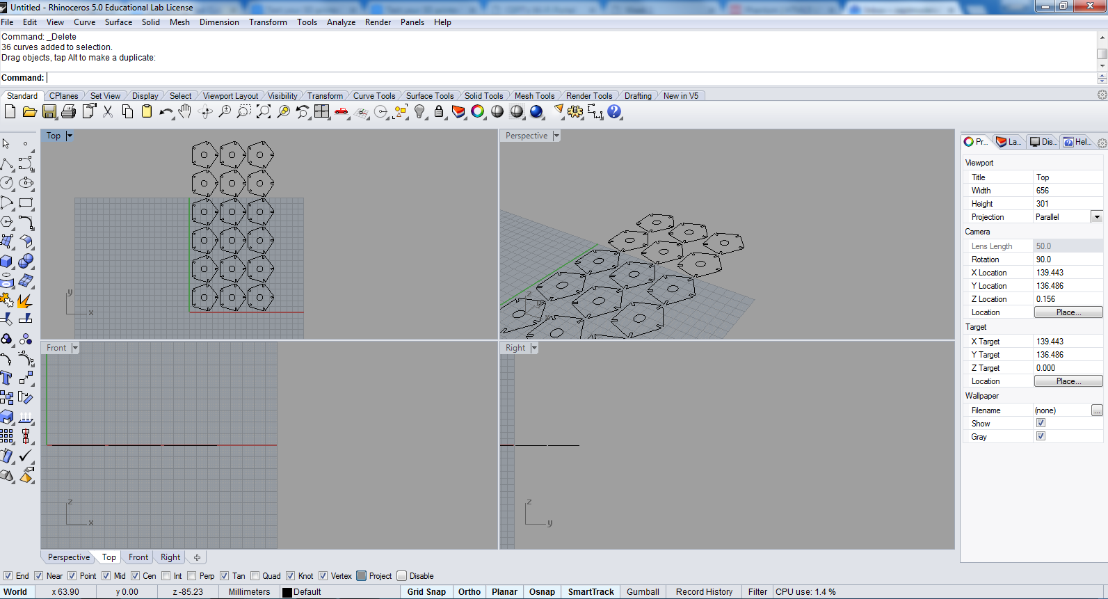
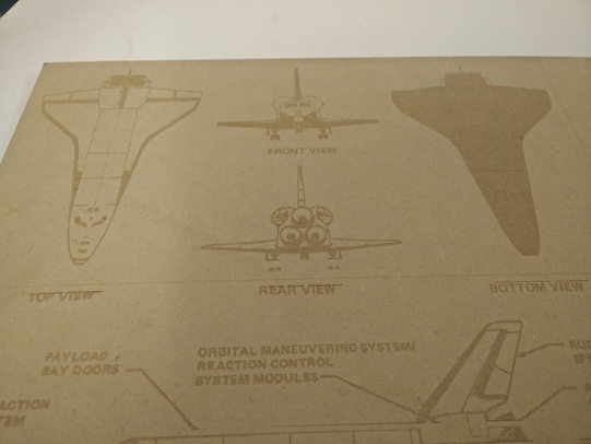
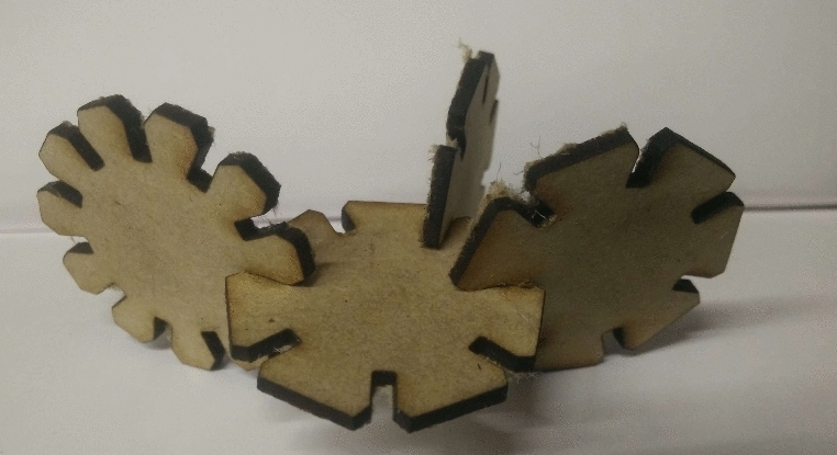
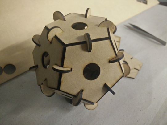
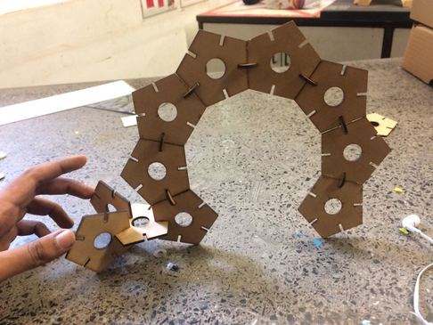
Using Antimony to make the drawing (pictures)
The nodes are as folows - ( A Rectangle ) node is CSG ( diffrence subtracted ) from the notch which is a ( union ) of a (rectangle) and a (triangle) which ( array's ) around the verticies of the polygon.
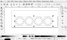
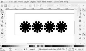
Using inkscape to convert a png to a vector format
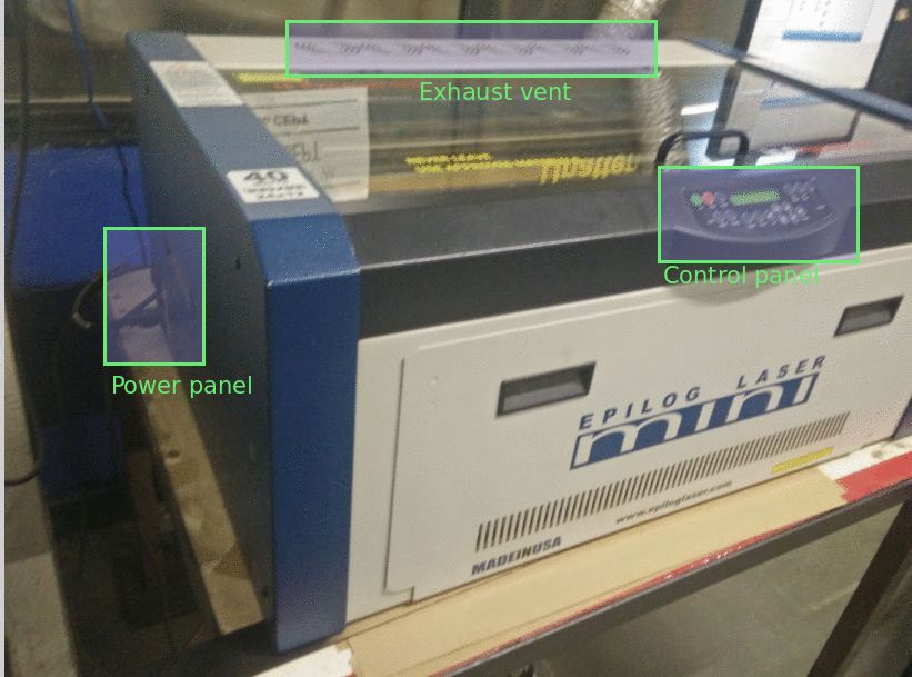
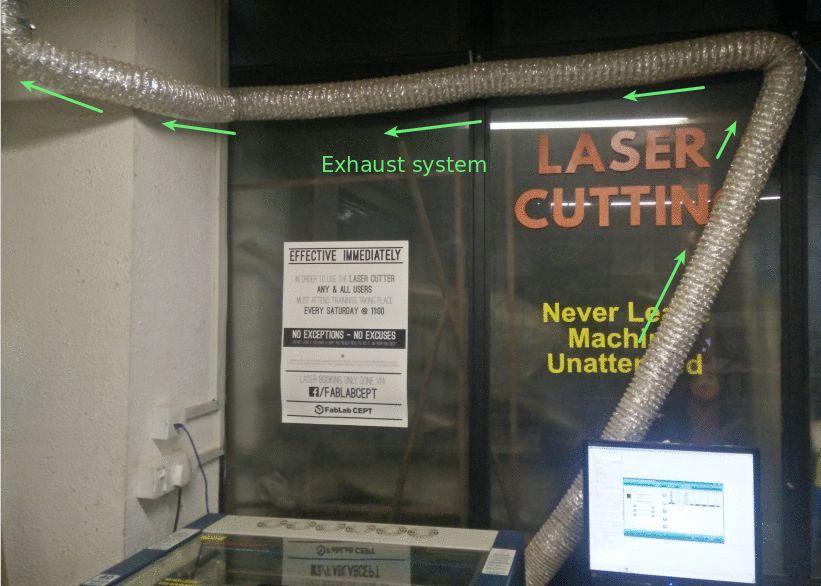
Workflow with laser cutter
Our laser cutter is an Epilog Mini 24" - It is interfaced through 'Rhinocerous' - a CAD software which runs on windows


 >
> 


