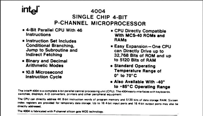
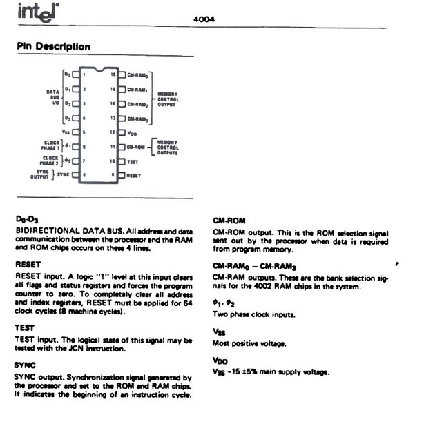
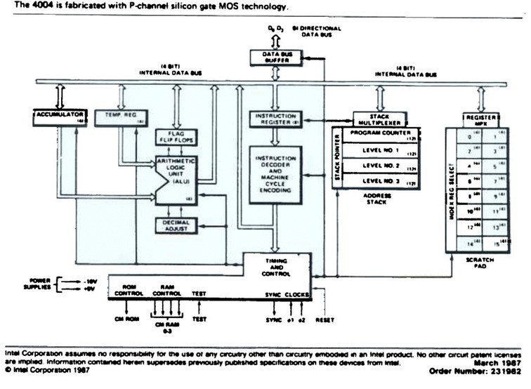
The summary sheet of the intel 4004 chip
Greetings, here lies my work-log at
______    _      ___                _                             _____  _____  __   ______
|  ___|  | |    / _ \              | |                           / __  \|  _  |/  | |___  /
| |_ __ _| |__ / /_\ \ ___ __ _  __| | ___ _ __ ___  _   _       `' / /'| |/' |`| |    / /
|  _/ _` | '_ \|  _  |/ __/ _` |/ _` |/ _ \ '_ ` _ \| | | |        / /  |  /| | | |   / /
| || (_| | |_) | | | | (_| (_| | (_| |  __/ | | | | | |_| |      ./ /___\ |_/ /_| |_./ /
\_| \__,_|_.__/\_| |_/\___\__,_|\__,_|\___|_| |_| |_|\__, |      \_____/ \___/ \___/\_/
                                                        |_|
Microcontroller Datasheets are documents provided by the manuafacturer which contain technical and performance characteristics of the microcontroller in sufficient detail, such that the user can integrate the component on a design / system (para-phrased from the Datasheet wikipedia article)
Out of curiosity, I tried to look up one of the first commercially available microcontroller and it's datasheet (hoping that a relatively primitive controller might be easier to comprehend, probably a wrong assumption) and stumbled upon the Intel 4004 chip and it's datasheet. Following is a comparative look at the 4004 intel chip and the atmel attiny44 chip we used in the hello.echo board whilst learning electronics design.
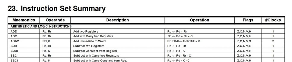
Datasheets often begin with summary sheets which states all major features and specifications of the microcontroller
| ~ | Intel 4004 | Attiny 24/44/84 | comments |
|---|---|---|---|
| x-bit | 4-bit | 8-bit | 8-bit |
| Naming convention | 4004 stands for | 94 | 8-bit |
| Architecture | ? | RISC | 8-bit |
| 8-bit |
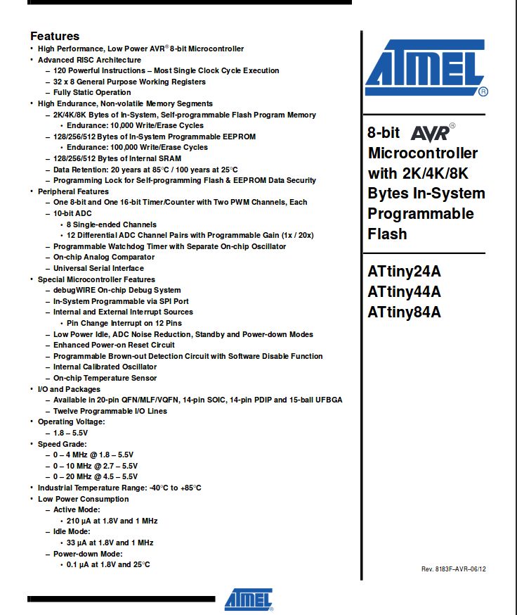
Datasheets often begin with summary sheets which states all major features and specifications of the microcontroller
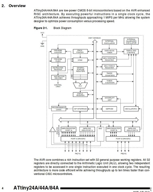
Microcontrollers have multiple parts / peripherals like clocks and memory units, a block diagram gives the layout of all these parts
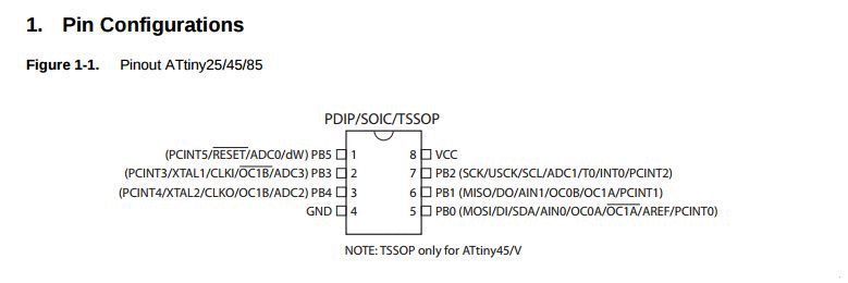
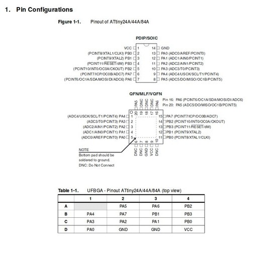
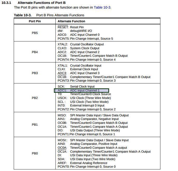
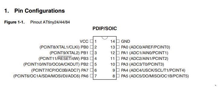
The pinout diagram from the datasheet is what I used to pick the digital pin I needed to be the ADC (Analog to Digital Converter)
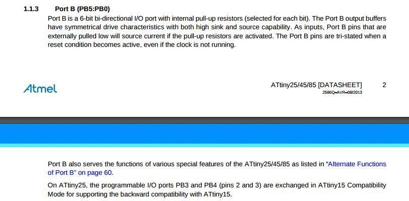
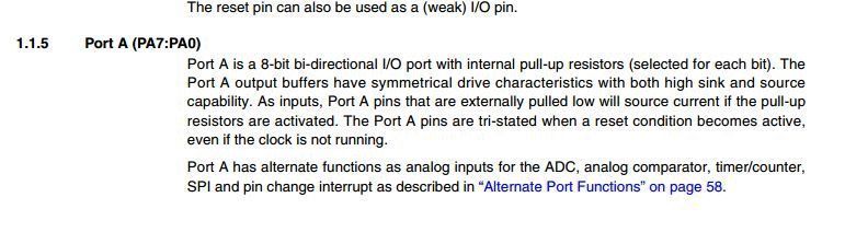
I selected PB2 - it is a general I/O port and the description is as follows
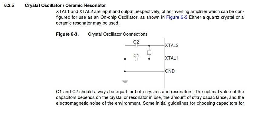
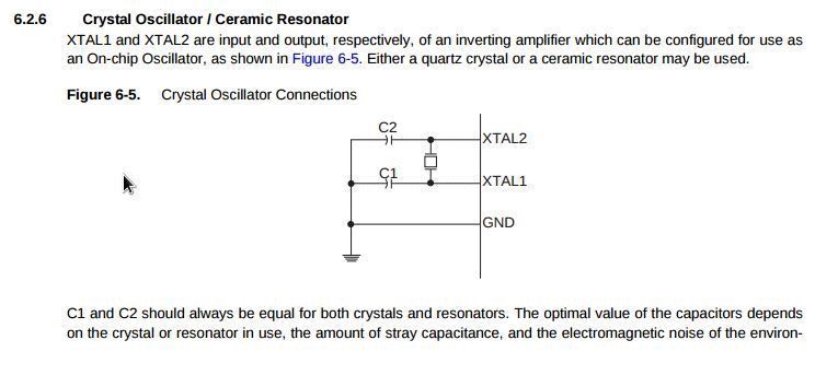
While doing ADC , it is generally recommended to use an external clock for better accuracy, so i looked into the clock systems mentioned in the datasheet, but however later decided to try the board on the internal clock first, to see how much the internal clock's inaccuracy affects the readings
I used arduino libraries and the arduino IDE to program the board - the command to intitialize Analog reading is 'analogRead'
define tempPin A1 //Defining the pin A1 as the data pin
int val;
void setup()
{
  myserial.begin(9600); //serial begins at 9600 baud rate
  pinMode(A1, INPUT);  //pin A1 becomes an input now
}

void loop()
{
  val = analogRead(tempPin);
  float mv = ( val / 1024.0) * 5000; //mapping analog values to relevant temperature readings
  float cel = mv / 10;
  float farh = (cel * 9) / 5 + 32; //farh to cel conversion

  myserial.print((char)cel);
  delay(10);
}
ALl the alternate functions of each pin, the one I need is a pin with ADC
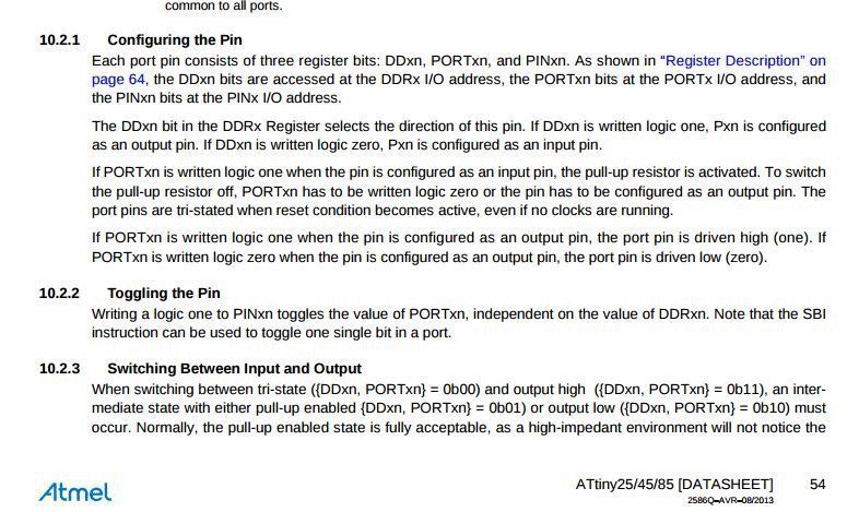
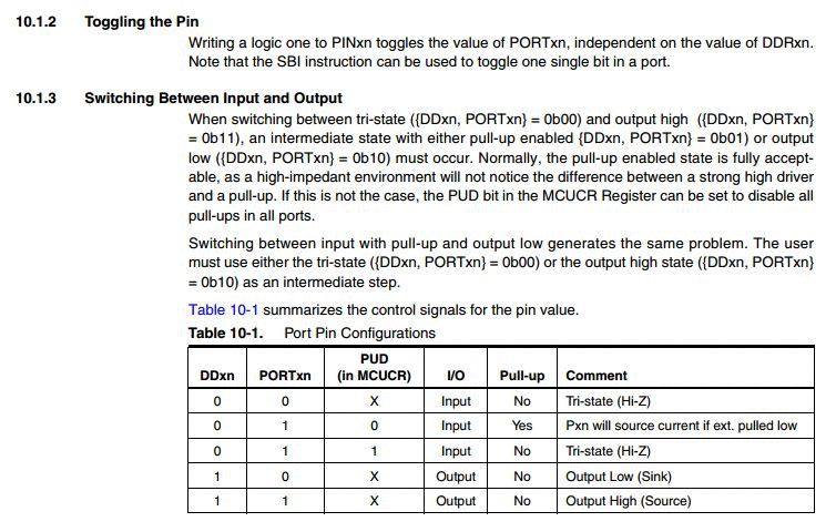
Details on how to toggle pins to different states
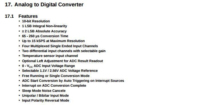
Basic overview of ADC features of an ADC pin
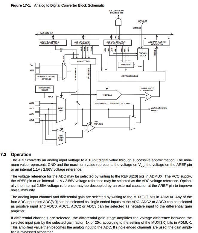
This is the block diagram of the ADC, fascinating stuff
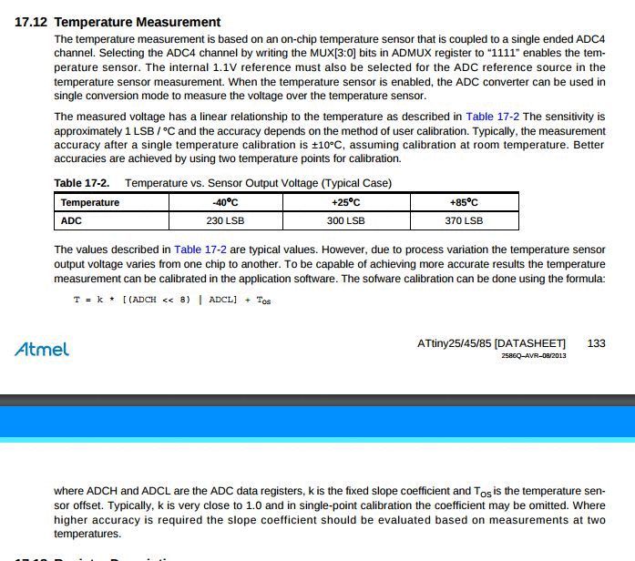
The chip has an in-built temperature sensor but it can't be put to service as a temperature sensor like LM35
The pinout diagram from the datasheet is what I used to pick the digital pin I needed to drive the gate of the n-mosfet
I selected PA1 - it is a general I/O port and the description is as follows
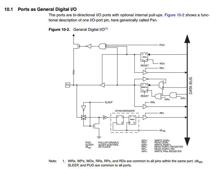
The block diagram for a I/O pin
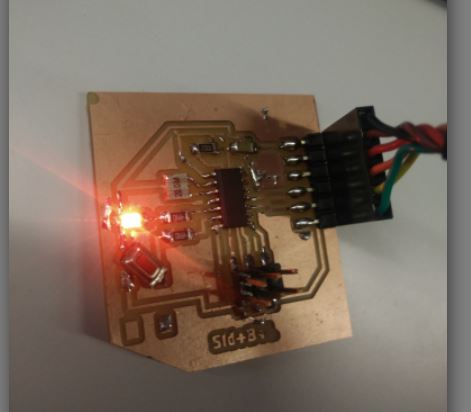
I used arduino libraries to toggle the pins on/off as seen in the part-code below
void loop() {
  digitalWrite(8, HIGH);   // turn the MOSFET-GATE on (HIGH is the voltage level)
the command digitalWrite is doing the following
The pinout diagram from the datasheet is what I used to pick the digital pin I needed to be the ADC (Analog to Digital Converter)
I selected PB2 - it is a general I/O port and the description is as follows
While doing ADC , it is generally recommended to use an external clock for better accuracy, so i looked into the clock systems mentioned in the datasheet, but however later decided to try the board on the internal clock first, to see how much the internal clock's inaccuracy affects the readings
I used arduino libraries and the arduino IDE to program the board - the command to intitialize Analog reading is 'analogRead'
define tempPin A1 //Defining the pin A1 as the data pin
int val;
void setup()
{
  myserial.begin(9600); //serial begins at 9600 baud rate
  pinMode(A1, INPUT);  //pin A1 becomes an input now
}

void loop()
{
  val = analogRead(tempPin);
  float mv = ( val / 1024.0) * 5000; //mapping analog values to relevant temperature readings
  float cel = mv / 10;
  float farh = (cel * 9) / 5 + 32; //farh to cel conversion

  myserial.print((char)cel);
  delay(10);
}
ALl the alternate functions of each pin, the one I need is a pin with ADC
Details on how to toggle pins to different states
Basic overview of ADC features of an ADC pin
This is the block diagram of the ADC, fascinating stuff
The chip has an in-built temperature sensor but it can't be put to service as a temperature sensor like LM35
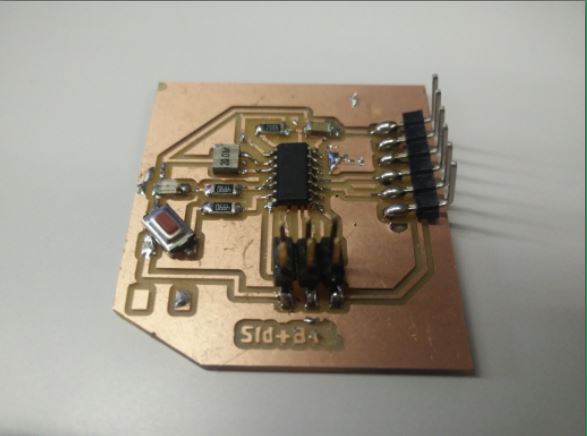
This week served as an introduction to the world of arduinos for me, and as Neil emphasises an arduino could refer to the following things
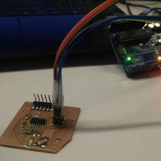
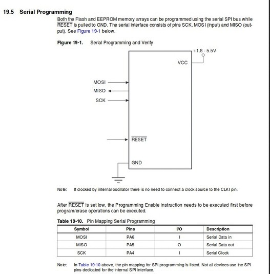
Programming attempt with avrDude and FabISP failed, yet to debug the issue,
Programming with arduino IDE and 'arduino Uno' as ISP seems to never fail
Through an example blink sketch - i learnt about the following concept - Digital IN, HIGH, LO. The tri-state of pins - 0, 1 , X. Pull-up and pull-down resistors. RX and TX
//Simple blink sketch, only changing the approproate Pin according to my design


void setup() {
  // initialize digital pin LED_BUILTIN as an output.
  pinMode(4, OUTPUT);
}

// the loop function runs over and over again forever
void loop() {
  digitalWrite(4, HIGH);   // turn the LED on (HIGH is the voltage level)
  delay(1000);                       // wait for a second
  digitalWrite(4, LOW);    // turn the LED off by making the voltage LOW
  delay(1000);                       // wait for a second
}