

Final Project - Software
HRW OpenHydroponicGrowbox
![]()
![]()
![]()
![]()
Software:
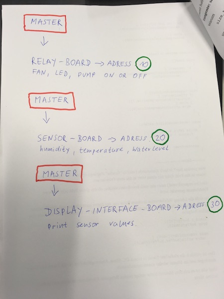
On the following illustartion you can see the Dataflow with the i2c adresses of each board:
![]()
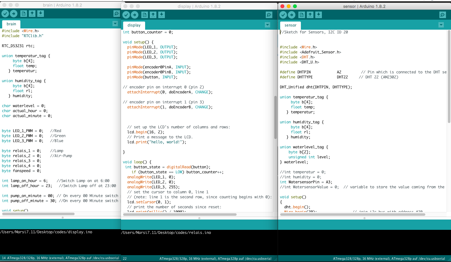
That was the most time intensive part of the final project. Testing and improvements in the programs have lasted about 3 days for the basic function (Interface with humidity and temperature, water level sensor, a RGB LED and the Real Time Clock).
As programmer I used the AVRISP mkII:
![]()
My controll-units are interconnected via I2C-protocoll. For the software of my individual control units, I first looked in the networking and communications week, the wire librarys from the Arduino IDE and moidied them for my final project.
![]()
Master-unit (Brain-board):
In this sketch you can see, that I included a real time clock (RTClib.h). I set it that the Pump goes every hour on (for 30 minutes). The Led is settet to get on at 6 o clock in the morning and turns of at 23 o clock at the evening.
Here you can see how I programm it:
      int lamp_on_hour = 6;    //Switch Lamp on at 6:00
int lamp_off_hour = 23;   //Switch Lamp off at 23:00


      if ((now.hour() >= lamp_on_hour) && (now.hour() < lamp_off_hour)) relais_2 = 1;
else relais_2 = 0;

if ((now.minute() >= pump_on_minute) && (now.minute() < pump_off_minute)) relais_1 = 1;
else relais_1 = 0;
Here you can see the detail for the waterlevelsensor:
void loop()
{
DateTime now = rtc.now();
actual_hour = now.hour();
actual_minute = now.minute();

read_sensors();
if (waterlevel == 1) {
  LED_2_PWM = 0;
  LED_3_PWM = 250;
  }
if (waterlevel == 2) {
  LED_2_PWM = 250;
  LED_3_PWM = 0;
}
Here you can see, that I have programm a humidity controll. If the DHT measure a humidity over or equal 50 % the fan turns on:
    if (humidity.rl >=50) fanspeed = 200;
    else if (humidity.rl <=45) fanspeed = 0;
Sketch for master-unit (Brain-board):
#include
#include "RTClib.h"

RTC_DS3231 rtc;

union temperatur_tag {
     byte b[4];
     float temp;
   } temperatur;

union humidity_tag {
     byte b[4];
     float rl;
   } humidity;

char waterlevel = 0;
char actual_hour = 0;
char actual_minute = 0;


byte LED_1_PWM = 0;   //Red
byte LED_2_PWM = 0;   //Green
byte LED_3_PWM = 0;   //Blue

byte relais_1 = 0;    //Lamp
byte relais_2 = 0;    //Air-Pump
byte relais_3 = 0;
byte relais_4 = 0;
byte fanspeed = 0;

int lamp_on_hour = 6;    //Switch Lamp on at 6:00
int lamp_off_hour = 23;   //Switch Lamp off at 23:00

int pump_on_minute = 00; // On every 00 Minute switch pump on (00:00, 01:00 02:00 ...)
int pump_off_minute = 30; //On every 00 Minute switch pump off (00:30 01:30 02:30 ...)

void setup()
{
  Wire.begin(); // join i2c bus (address optional for master)
  Wire.setClock(50000);
  temperatur.temp = 0;
humidity.rl = 0;
waterlevel = 0;
rtc.begin();
//rtc.adjust(DateTime(2017, 6,  9,  17, 21, 0));

}

byte x = 0;

void loop()
{
DateTime now = rtc.now();
actual_hour = now.hour();
actual_minute = now.minute();

read_sensors();
if (waterlevel == 1) {
  LED_2_PWM = 0;
  LED_3_PWM = 250;
  }
if (waterlevel == 2) {
  LED_2_PWM = 250;
  LED_3_PWM = 0;
}

refresh_display();

if (humidity.rl >=50) fanspeed = 200;
else if (humidity.rl <=45) fanspeed = 0;

if ((now.hour() >= lamp_on_hour) && (now.hour() < lamp_off_hour)) relais_2 = 1;
else relais_2 = 0;

if ((now.minute() >= pump_on_minute) && (now.minute() < pump_off_minute)) relais_1 = 1;
else relais_1 = 0;


refresh_relais();

delay(5000);

}

void refresh_display(void)
{
  char msg[13];
  int i;

  msg[0] = temperatur.b[0];
  msg[1] = temperatur.b[1];
  msg[2] = temperatur.b[2];
  msg[3] = temperatur.b[3];
  msg[4] = humidity.b[0];
  msg[5] = humidity.b[1];
  msg[6] = humidity.b[2];
  msg[7] = humidity.b[3];
  msg[8] = waterlevel;
  msg[9] = LED_1_PWM;
  msg[10] = LED_2_PWM;
  msg[11] = LED_3_PWM;


  for (i=0;i<=11;i++){
    if (msg[i] == 0) msg[i] = 1;
  }

  Wire.beginTransmission(30);
  Wire.write(msg);
  Wire.write(actual_hour);
  Wire.write(actual_minute);
  Wire.endTransmission();
}

void refresh_relais (void)
{
  Wire.beginTransmission(10); // transmit to device #10
  Wire.write(relais_1);
  Wire.write(relais_2);
  Wire.write(relais_3);
  Wire.write(relais_4);
  Wire.write(fanspeed);
  Wire.endTransmission();    // stop transmitting
}

void read_sensors (void)
{
  Wire.requestFrom(20, 9);    // request 10 bytes from slave device #20

  while (Wire.available())   // slave may send less than requested
  {char msg[9];
  msg[0] = Wire.read();
  msg[1] = Wire.read();
  msg[2] = Wire.read();
  msg[3] = Wire.read();

  msg[4] = Wire.read();
  msg[5] = Wire.read();
  msg[6] = Wire.read();
  msg[7] = Wire.read();

  msg[8] = Wire.read();

if ((msg[1] != 'n') && (msg[2] != 'a')){
  temperatur.b[0] = msg[1];
  temperatur.b[1] = msg[2];
  temperatur.b[2] = msg[3];
  temperatur.b[3] = msg[4];}

if ((msg[4] != 'n') && (msg[5] != 'a')){
  humidity.b[0] = msg[5];
  humidity.b[1] = msg[6];
  humidity.b[2] = msg[7];
  humidity.b[3] = msg[8];}

  waterlevel = msg[0];
  }
}
![]()
Sketch for slave-unit 1 (Relay-board adress = 10):
//Relaisboard for Growbox
//I2C-Slave-Address: 10
//Receives 5 bytes
//Byte 1-4 = Relaisstate 1-4
//Byte 5 = Fanspeed

#include

int fan = 5;   //PWM Pin for Fan
int relais1 = 10; //Output Pin for Relais 1
int relais2 = 9; //Output Pin for Relais 2
int relais3 = 8; //Output Pin for Relais 3
int relais4 = 7; //Output Pin for Relais 4

void setup() {
    // Init the I2C-Bus
  Wire.begin(10);                // join i2c bus with address #10
  Wire.onReceive(receiveEvent); // register event

  // Declare Fan and Relaispins as OUTPUT
  pinMode(fan, OUTPUT);
  pinMode(relais1, OUTPUT);
  pinMode(relais2, OUTPUT);
  pinMode(relais3, OUTPUT);
  pinMode(relais4, OUTPUT);


  //Set all Relais to off, Fanspeed to 0
  digitalWrite(relais1, HIGH);
  digitalWrite(relais2, HIGH);
  digitalWrite(relais3, HIGH);
  digitalWrite(relais4, HIGH);
  analogWrite(fan, 0);
}

void loop() {

  delay(1000);
}

// function that executes whenever data is requested by master
// this function is registered as an event, see setup()
// the function get all bytes from the i2c-bus:
// Byte 1 : Relais 1
// Byte 2 : Relais 2
// Byte 3 : Relais 3
// Byte 4 : Relais 4
// Byte 5 : PWM-Value for Fan
void receiveEvent(int howMany)
{
    char relais_1 = 0;
    char relais_2 = 0;
    char relais_3 = 0;
    char relais_4 = 0;
    char fanspeed = 0;

  while (0 < Wire.available()) // loop through all received bytes
    {
    relais_1 = Wire.read();
    relais_2 = Wire.read();
    relais_3 = Wire.read();
    relais_4 = Wire.read();
    fanspeed = Wire.read();
    while (0 < Wire.available()) // loop through all received bytes
      {
      int rest = Wire.read(); //read all bytes over, if there is a failure
      }
    }

    //Set the Relais-Output due to the received byte, invers-logic!
    if (relais_1 == 1) digitalWrite(relais1, LOW);
    else digitalWrite(relais1, HIGH);

    //Set the Relais-Output due to the received byte, invers-logic!
    if (relais_2 == 1) digitalWrite(relais2, LOW);
    else digitalWrite(relais2, HIGH);

    //Set the Relais-Output due to the received byte, invers-logic!
    if (relais_3 == 1) digitalWrite(relais3, LOW);
    else digitalWrite(relais3, HIGH);

    //Set the Relais-Output due to the received byte, invers-logic!
    if (relais_4 == 1) digitalWrite(relais4, LOW);
    else digitalWrite(relais4, HIGH);

    //Set the PWM for the fan
    analogWrite(fan, fanspeed);
}
![]()
Sketch for slave-unit 2 (Sensor-board on i2c bus adress = 20):
//Sketch for Sensors, I2C ID 20


#include  <Wire.h>
#include <Adafruit_Sensor.h>
#include <DHT.h>
#include <DHT_U.h>

#define DHTPIN            A2         // Pin which is connected to the DHT sensor.
#define DHTTYPE           DHT22     // DHT 22 (AM2302)

DHT_Unified dht(DHTPIN, DHTTYPE);

union temperatur_tag {
     byte b[4];
     float temp;
   } temperatur;

union humidity_tag {
     byte b[4];
     float rl;
   } humidity;

union waterlevel_tag {
    byte b[2];
    unsigned int level;
} waterlevel;

//int temperatur = 0;
//int humidity = 0;
int WatersensorPin = A3;
//int WatersensorValue = 0;  // variable to store the value coming from the watersensor

void setup()
{
  dht.begin();
  Wire.begin(20);                // join i2c bus with address #20
  Wire.onRequest(requestEvent); // register event
}

void loop()
{
  waterlevel.level = analogRead(WatersensorPin);
  sensors_event_t event;
  dht.temperature().getEvent(&event);
  temperatur.temp = event.temperature;
  dht.humidity().getEvent(&event);
  humidity.rl = event.relative_humidity;


  delay(2000);
}

// function that executes whenever data is requested by master
// this function is registered as an event, see setup()
void requestEvent()
{
  char msg[10];
  msg[0] = temperatur.b[0];
  msg[1] = temperatur.b[1];
  msg[2] = temperatur.b[2];
  msg[3] = temperatur.b[3];
  msg[4] = humidity.b[0];
  msg[5] = humidity.b[1];
  msg[6] = humidity.b[2];
  msg[7] = humidity.b[3];
  msg[8] = waterlevel.b[0];
  msg[9] = waterlevel.b[1];
  Wire.write(msg);
}
![]()
Sketch for slave-unit 3 (Display-board i2c address = 30):
/*
  LiquidCrystal Library - Interface for Growbox

 Demonstrates the use a 16x2 LCD display.  The LiquidCrystal
 library works with all LCD displays that are compatible with the
 Hitachi HD44780 driver. There are many of them out there, and you
 can usually tell them by the 16-pin interface.

 This sketch prints "Hello World!" to the LCD
 and shows the time.

  The circuit:
 * LCD RS pin to digital pin 12
 * LCD Enable pin to digital pin 11
 * LCD D4 pin to digital pin 5
 * LCD D5 pin to digital pin 4
 * LCD D6 pin to digital pin 3
 * LCD D7 pin to digital pin 2
 * LCD R/W pin to ground
 * LCD VSS pin to ground
 * LCD VCC pin to 5V
 * 10K resistor:
 * ends to +5V and ground
 * wiper to LCD VO pin (pin 3)

 Library originally added 18 Apr 2008
 by David A. Mellis
 library modified 5 Jul 2009
 by Limor Fried (http://www.ladyada.net)
 example added 9 Jul 2009
 by Tom Igoe
 modified 22 Nov 2010
 by Tom Igoe

 This example code is in the public domain.

 http://www.arduino.cc/en/Tutorial/LiquidCrystal
 */

// include the library code:
#include <LiquidCrystal.h>

#define encoder0PinA 2
#define encoder0PinB 3

// initialize the library with the numbers of the interface pins
LiquidCrystal lcd(12, 11, 5, 4, A1, A0);

int LED_1 = 6;  //BLUE
int LED_2 = 9;  //GREEN
int LED_3 = 10; //RED

int button = A3;

int rotary_counter = 0;
int button_counter = 0;

void setup() {
  pinMode(LED_1, OUTPUT);
  pinMode(LED_2, OUTPUT);
  pinMode(LED_3, OUTPUT);

  pinMode(encoder0PinA, INPUT);
  pinMode(encoder0PinB, INPUT);
  pinMode(button, INPUT);

// encoder pin on interrupt 0 (pin 2)
  attachInterrupt(0, doEncoderA, CHANGE);

// encoder pin on interrupt 1 (pin 3)
  attachInterrupt(1, doEncoderB, CHANGE);


  // set up the LCD's number of columns and rows:
  lcd.begin(16, 2);
  // Print a message to the LCD.
  lcd.print("hello, world!");

}

void loop() {
 int button_state = digitalRead(button);
    if (button_state == LOW) button_counter++;
  analogWrite(LED_1, 0);
  analogWrite(LED_2, 0);
  analogWrite(LED_3, 255);
  // set the cursor to column 0, line 1
  // (note: line 1 is the second row, since counting begins with 0):
  lcd.setCursor(0, 1);
  // print the number of seconds since reset:
  lcd.print(millis() / 1000);
  lcd.print(" ");
  lcd.print(rotary_counter);
  lcd.print(" ");
  lcd.print(button_counter);
}

void doEncoderA(){

  // look for a low-to-high on channel A
  if (digitalRead(encoder0PinA) == HIGH) {

    // check channel B to see which way encoder is turning
    if (digitalRead(encoder0PinB) == LOW) {
      rotary_counter = rotary_counter + 1;         // CW
    }
    else {
      rotary_counter = rotary_counter - 1;         // CCW
    }
  }

  else   // must be a high-to-low edge on channel A
  {
    // check channel B to see which way encoder is turning
    if (digitalRead(encoder0PinB) == HIGH) {
      rotary_counter = rotary_counter + 1;          // CW
    }
    else {
      rotary_counter = rotary_counter - 1;          // CCW
    }
  }

}

void doEncoderB(){

  // look for a low-to-high on channel B
  if (digitalRead(encoder0PinB) == HIGH) {

   // check channel A to see which way encoder is turning
    if (digitalRead(encoder0PinA) == HIGH) {
      rotary_counter = rotary_counter + 1;         // CW
    }
    else {
      rotary_counter = rotary_counter - 1;         // CCW
    }
  }

  // Look for a high-to-low on channel B

  else {
    // check channel B to see which way encoder is turning
    if (digitalRead(encoder0PinA) == LOW) {
      rotary_counter = rotary_counter + 1;          // CW
    }
    else {
      rotary_counter = rotary_counter - 1;          // CCW
    }
  }

}
![]()
![]()
Download-Section:
![]()
![]()