

Week 3 - computer-controlled cutting
Group assignment:
make lasercutter test part(s), varying cutting settings and slot dimensions.
Individual assignment:
Cut something on the vinylcutter
design, make, and document a parametric press-fit construction kit,
accounting for the lasercutter kerf, which can be assembled in multiple ways.
1. Cut something on the vinylcutter
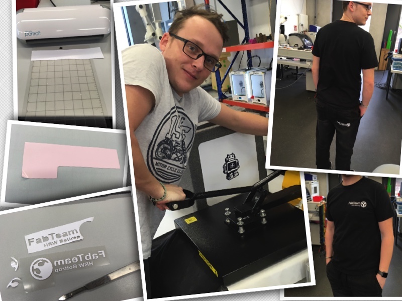
Let´s start with Vinyl-cutting. Neil told us, that the vinylcutter is one of the most underrated and least used machines in the FabLab. I can only confirm that. We have been working with the device regularly since we have a thermal tshirt-press.
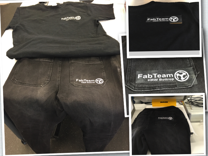
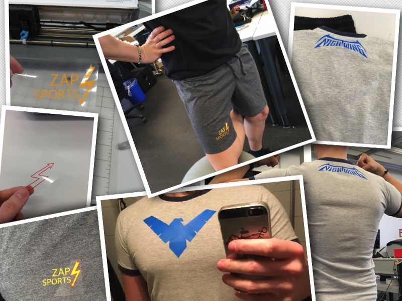
So what could I do with the vinylcutter? Stickers for my laptop? Hmm boring... So I thought it would be cool to make workwear, a leisure shirt and pants for my workouts.

- Hobbyplotter Silhouette Portrait, Cutting-mat and Soft-heat-transfer foil from: hobbyplotter.de
- First I have searched in the cabinet for old clothes, which are suitable for imprinting.
If you have nothing left in the closet you can also buy uncovered clothes: check out here
- For design and communication to the plotter you need the SILHOUETTE SOFTWARE
![]()
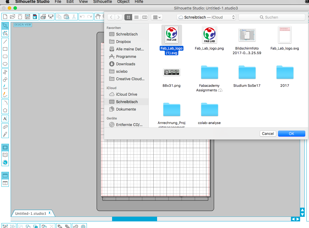
1. First I imported the FabLab logo from Wikipedia. Of course you can use any logo or drawing which you find suitable.
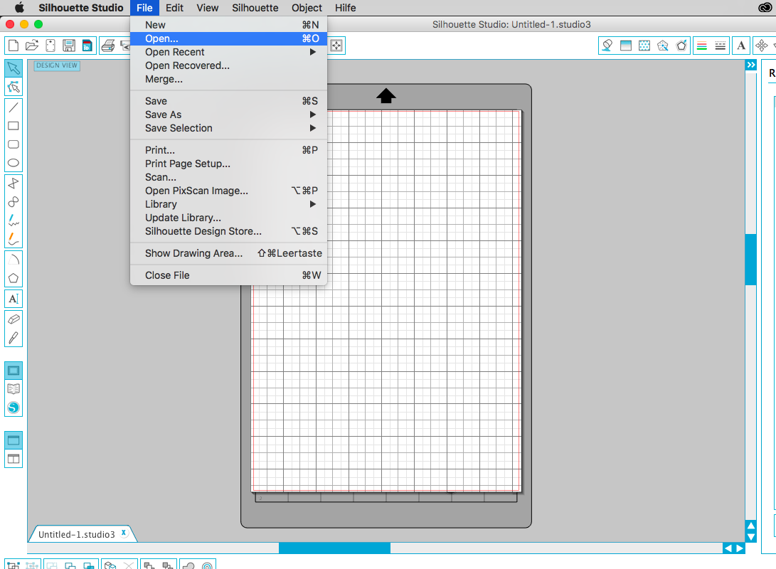
Import the Logo which you have saved on your computer under file -> open -> logo.svg:
![]()
2. Trace the design:
![]()
3. Use the filters to let the software recognize the logo:
![]()
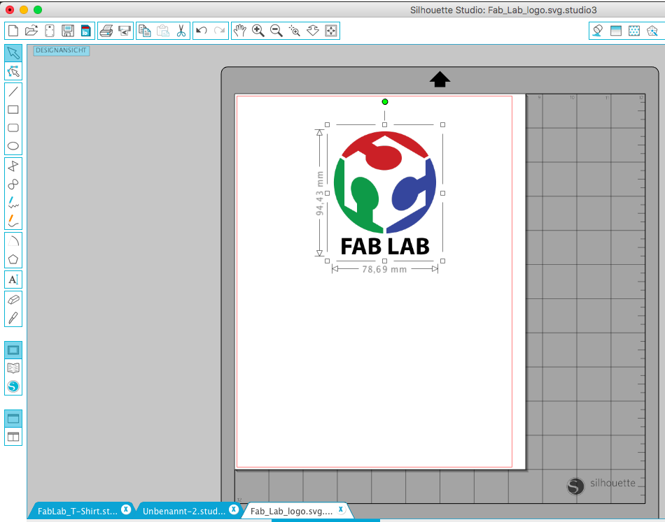
4. In the next step I placed a circle around the fablab logo and centered it:
![]()
5. Next I added the text style "FabTeam HRW Bottrop" to the logo. I use arial and a bold font:

![]()
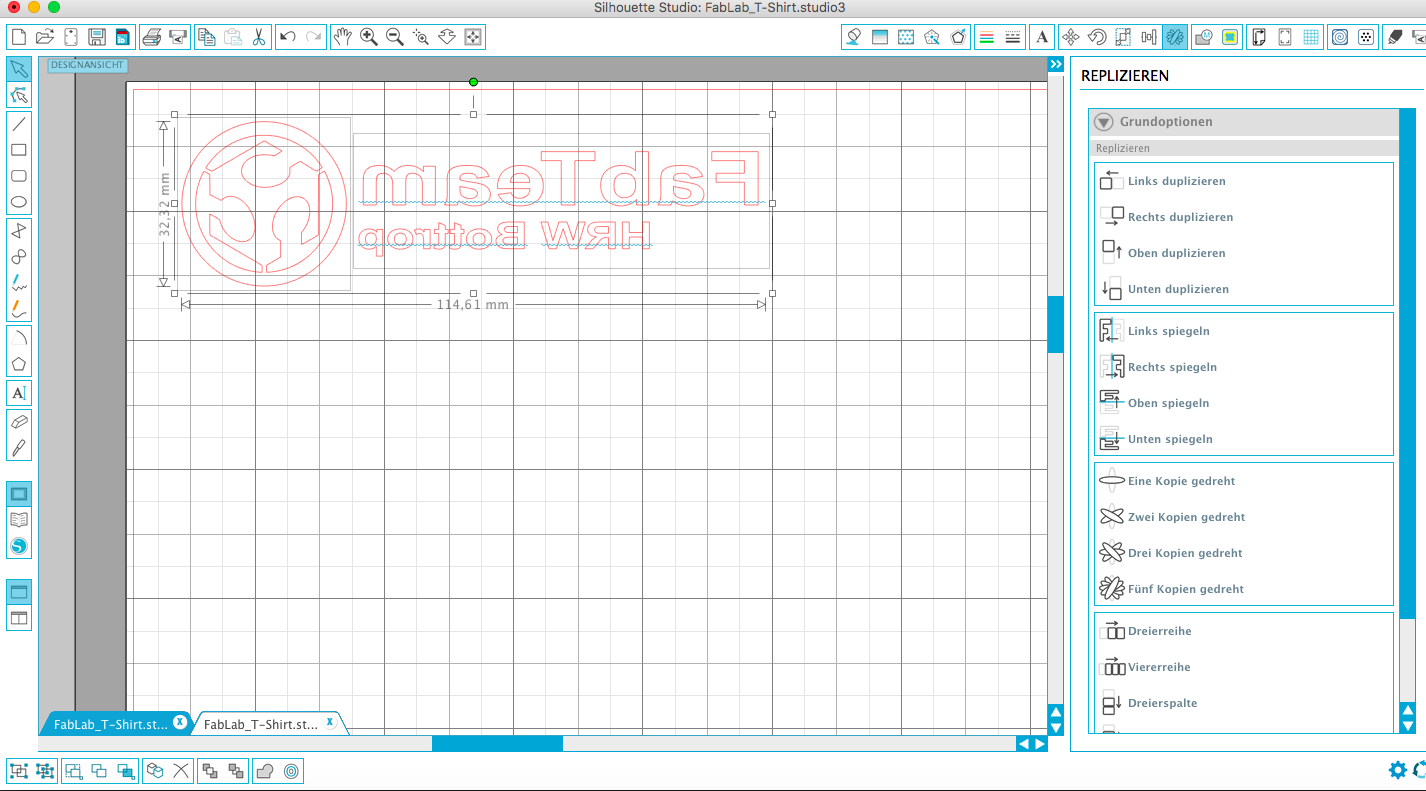
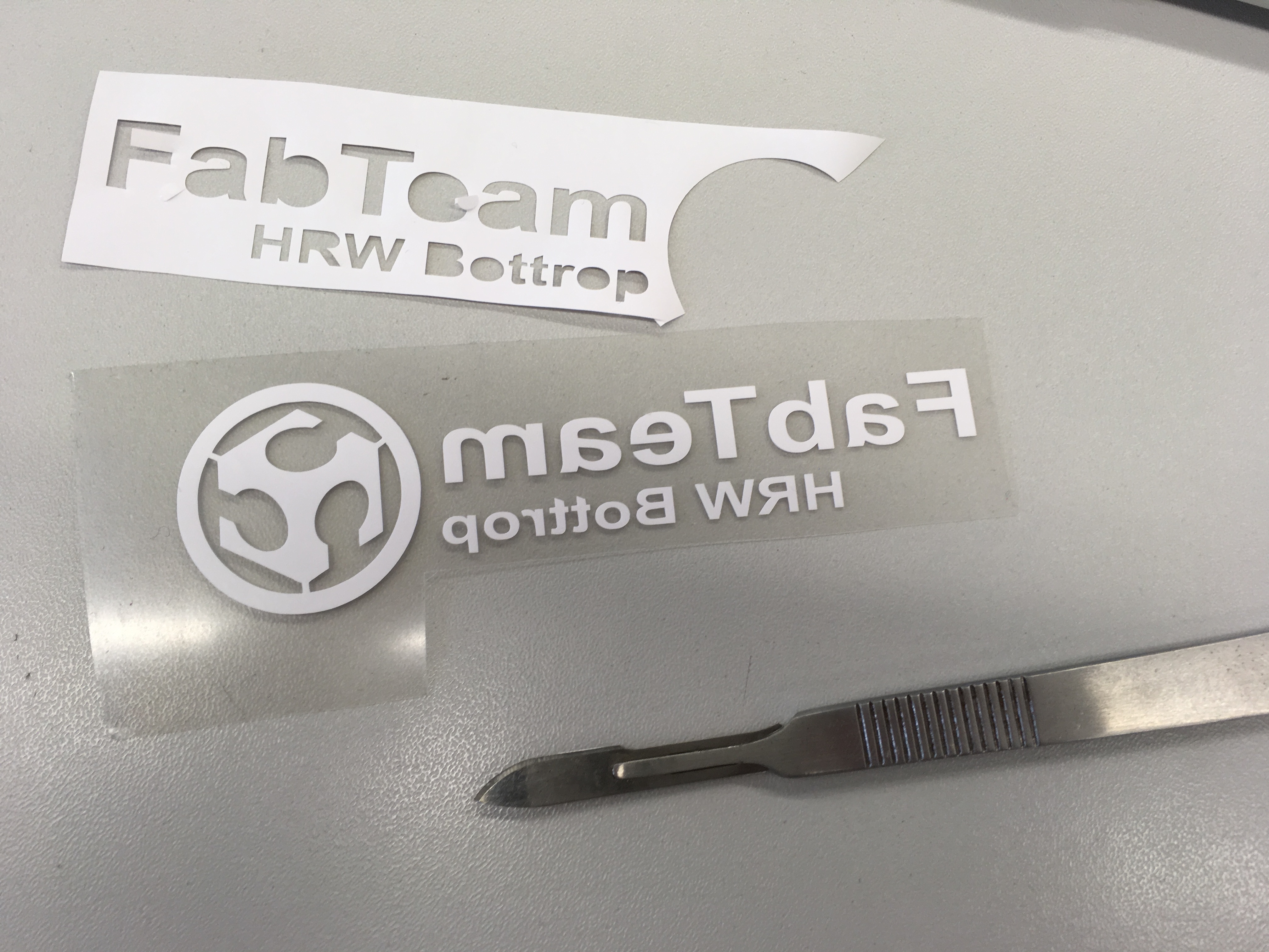
6. Mirror the design - with a normal vinyl sticker the reflection would not be necessary. Because I create logos for textiles I have to mirror my design so that the logo on the tshirt is right:
![]()
7. Design-Setting - Portrait Cutting Mat: 8x12 inches; A4 210mm x 297 mm:
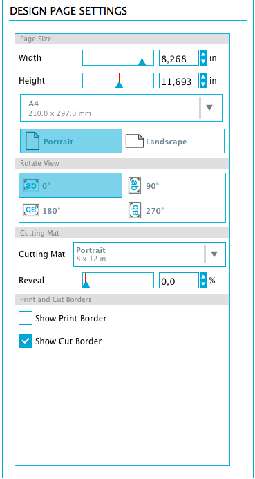
![]()
8. Cut-Settings - Cut Mode "Standard", Cut Style for Selected Shape "Cut", Material-Type "Heat Transfer Material" (Smooth):
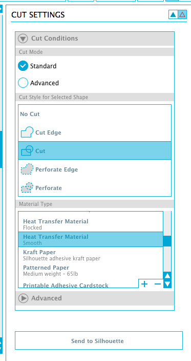
![]()
9. Ready to cut - Attetion: It is Important to lay the Material with the smooth (or shiny) site on the cutting-mat. After you have placed the mat in the vinlycutter you can press "Send to Silhouette"
![]()
Workflow:
Be creative! -> Design -> insert material -> cut -> prepare -> press -> have fun ;)
![]()
- For preparing and removing excess material after vinyl-cutting I suggest to use a scalpel like one of this scalpels
- Standard Transfer press from Helo: For Heat transfer Material (Schmooth) = 180 °C / 30 seconds from Ebay
Download-Section:
FabTeam Logo
Nightwing Logo
Nightwing bird design
Sportpant design
2. design a parametric press-fit construction kit
As already mentioned at the beginning of this documetation the vinylcutter is the least used device in our fablab. Now comes the part with the lasercutter, which is the most widely used device in our fablab. However, the lasercutter is also one of the most dangerous devices in the laboratory because of a very great risk of fire. For this reason, we have marked an area on our floor that should not be left during work on the machine.
![]()
Laser-Setup:

- Epilog Zing, 50 W Co2 Laser (600 x 300mm)
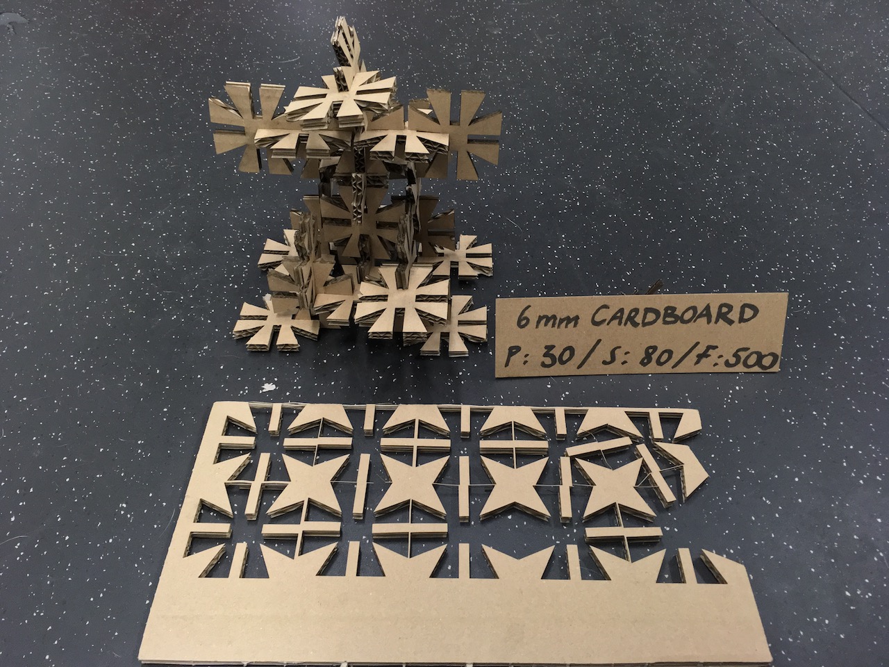
6mm cardboard pressfit-construction-kit
Working parametric in Fusion360°
![]()
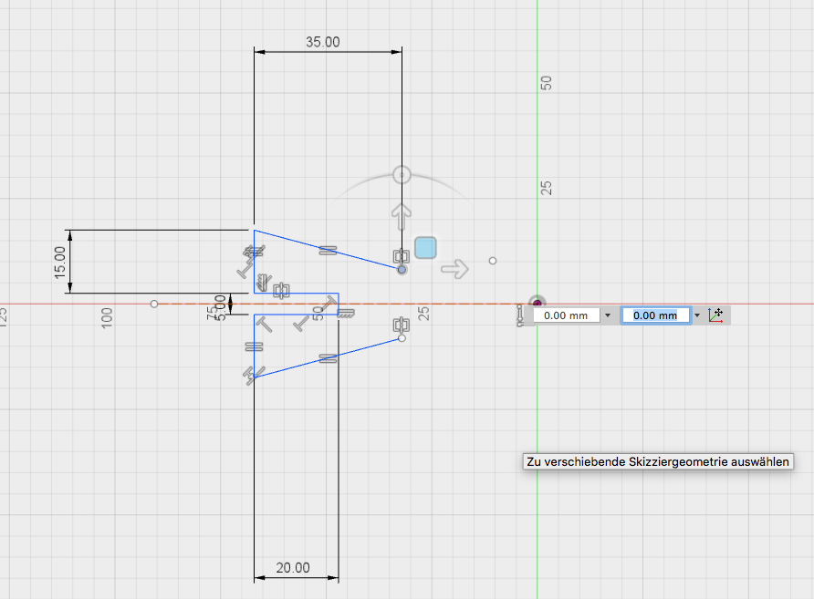
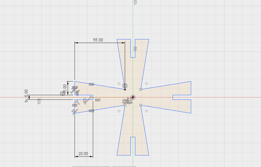
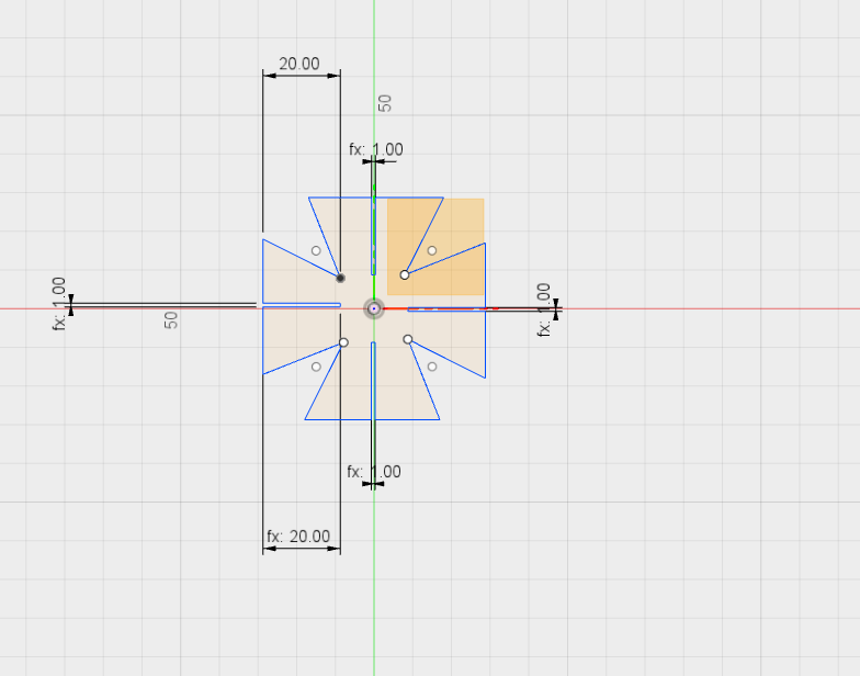
1. Sketch in Fusion 360 - Determine constrains and dimensions:
![]()
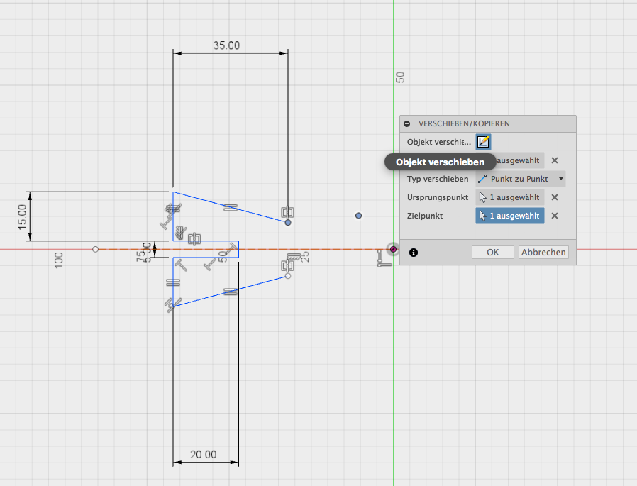
2 Sketch in Fusion 360 - Set a point and move the sketch to the point:
![]()
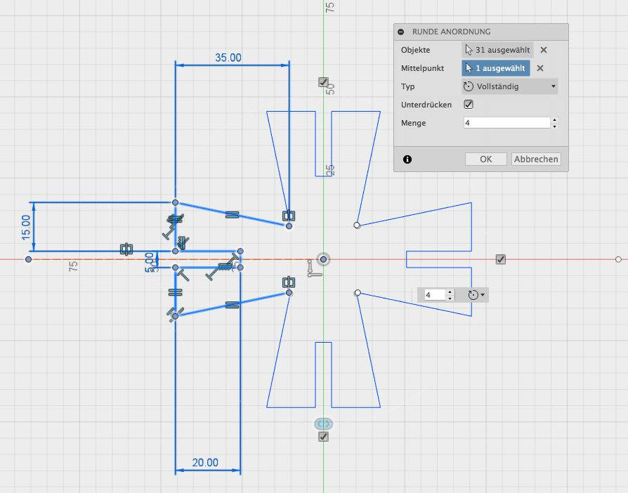
3. Sketch in Fusion 360 - Arrangement of the 4 legs from center (round):
![]()
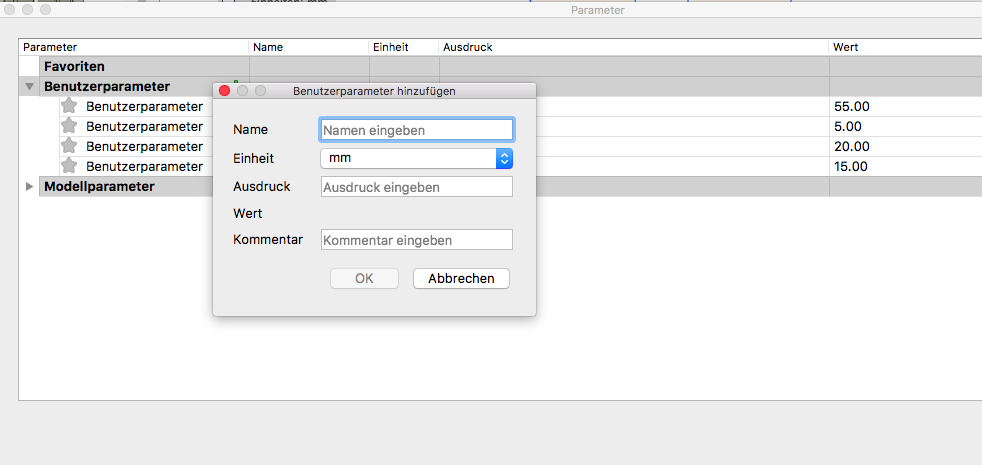
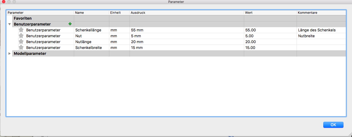
4. Sketch in Fusion 360 - Next I have fixed pramaters. First the length of the legs, the width of the legs, and as well as the length and width of the nut:
The parameters spreadsheet you find under "change" -> "parameters" . The parameters box contains every single dimension (variable) defined inside the model. You can also add your own. This is what we’ll be doing to make the parametric model. Set up the parameters for the model at first as far as you know with parameters are important. I focus here on joining parts together I thought that it is better to parameterize the connection part and the thickness of the material. This is important because different material sizes results in different connection joinings:
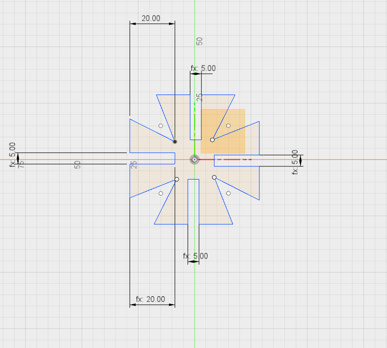
The clou at the parameteric design is now, that I change one of the of the value (width) and all the other values go to the same value. Here in this example from 5mm wide to 1mm wide.
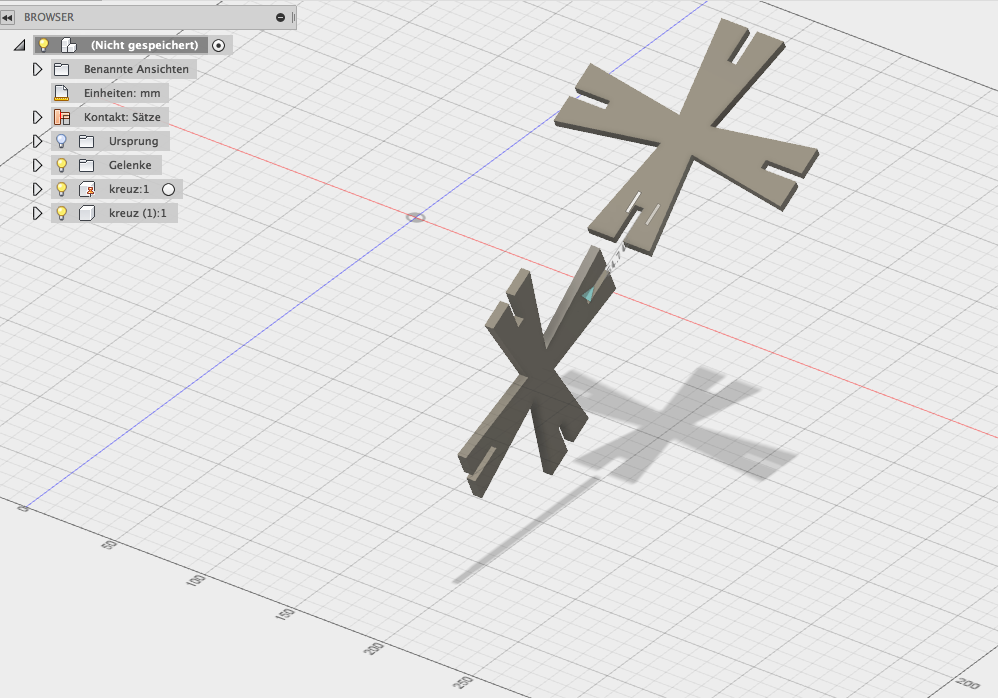
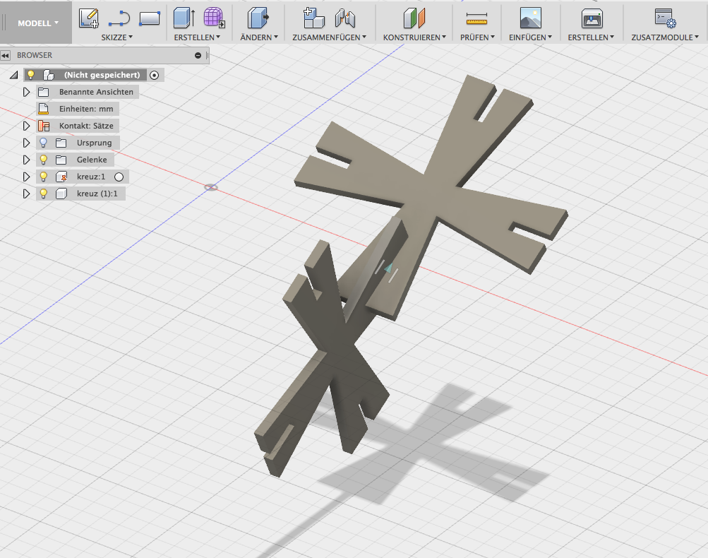
5. Extrusion and joining - Create a component, create copy to the first level, assemble the 2 3d models, fix, position determine and put together the models:
6. Ready to cut - Export file as DXF:
7. Ready to cut - open it with Visicut
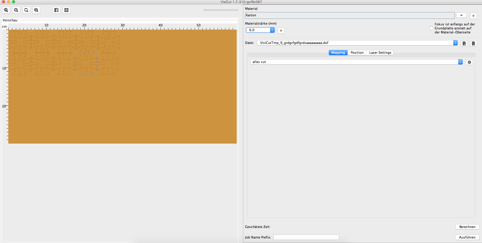
6mm Cardboard with 30 % power, 80% speed, 500 Hz. For a 6mm slot I need to design a 5,8 mm form width. 0,2 mm of the material have been vaporized by the lasercutter.
8. Setting focus and cutting on Lasercutter:
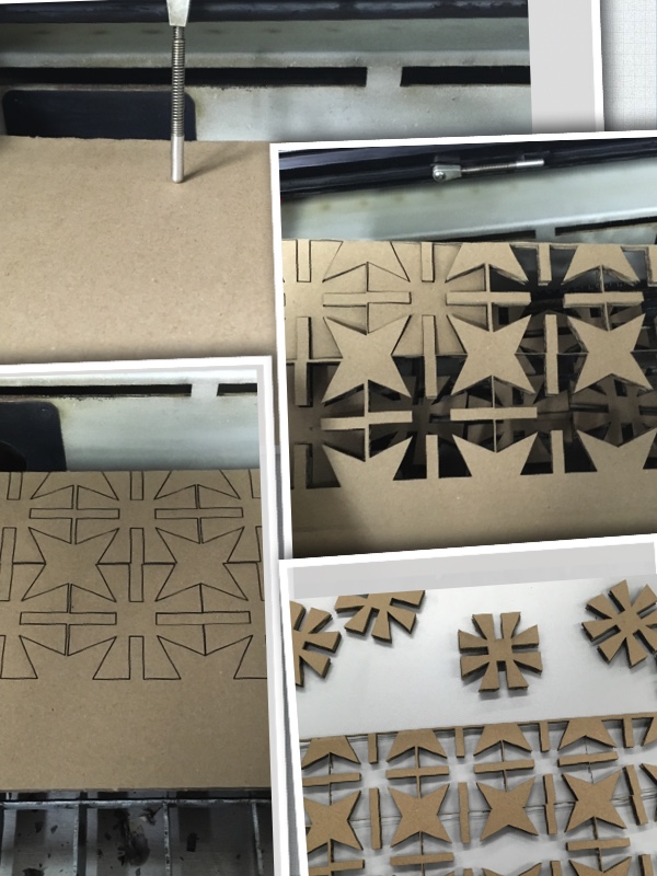
9. My ready assembled pressfit contruction kit:

Download-Section:
Fusion360
VisiCut
![]() Fusion360 file
Fusion360 file
VisiCut file
Pressfit DXF file