

Week 8 - Eembedded programming
![]()
![]()
![]()
Assignment
and programming environments as possible
![]()
![]()
With programming iam not very familar with. I had electrical engineering while studying, but that is very long ago. For this topic of the electronics development, as well as the programming, I really have to start at zero.
The main task of embedded programming is the microprocessor you will use or you want to deliver a package.
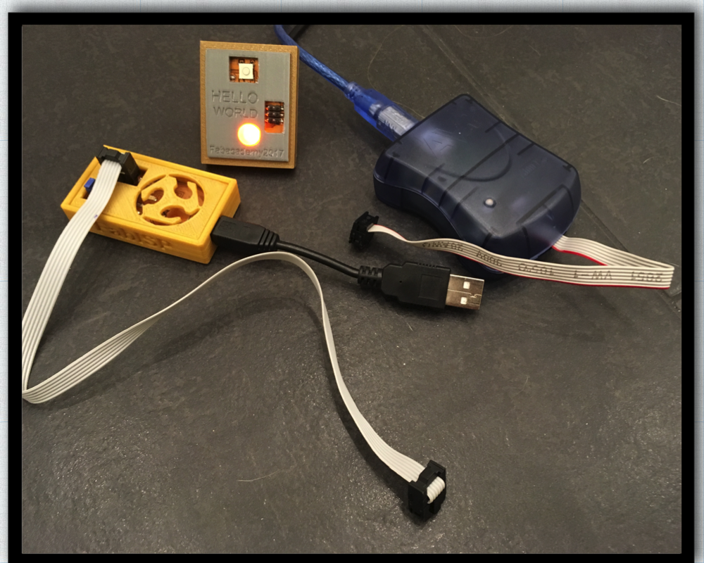
My board design is based on the fabacadamy's 6th electronics design explanations two weeks ago from Fabacademy Tutorial website. I added a LED and an 20MHz resonator to my board.
Now I have to program my board through my programmer, which we have made in the 4th week.
![]()
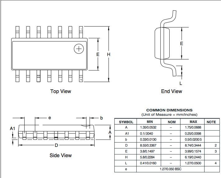
What information I have put together from the ATtiny44 Datasheet:
ATtiny44 Datasheet:
Overview
The Atmel ATtiny24/44/84 is a low-power CMOS 8-bit microcontroller based on the AVR enhanced RISC architecture. By executing powerful instructions in a single clock cycle, the Atmel ATtiny24/44/84 achieves throughputs approaching 1MIPS per MHz allowing the system designer to optimize power consumption versus processing speed.
![]()
including: C Compilers, Macro Assemblers, Program Debugger/Simulators and Evaluation kits.
The device is manufactured using Atmel´s high desity non-volatile memory-technology. The on-chip
ISP Flash allows the program memory to be re-programmed in-system through an SPI serial interface, by a conventional non-volatile memory programmer or by an on-chip boot code running on the AVR core.
![]()
![]()
Pin configuration Explanations from the Datasheet (page 60-65 in the Datasheet):
Possible PWM (Pulse Width Modulation) is on PA5,PA6 and PA7 and PB2. PWM you need for Informationtransfer and often to regulate the conversion of energy into technical systems.
![]()
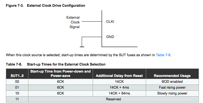
External Clock
To drive the device from an external clock source, CLKI should be driven as shown in Figure 7-3. To run the device on an external clock, the CKSEL fuses must be programmed to “0000”.
![]()
Thinks I like to know more:
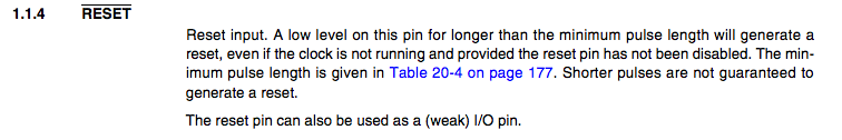
How to Reset?
![]()
What happen with unconnected pins?
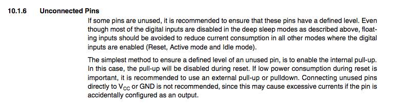
![]()
What does MISO, MOSI and SCK means?
On the following photo you can see the Pin Configuration of the ATiny24/44/84
My LED with a 330 Ω resistor is on Pin PA7 (blue underlined); the Button with the 10 kΩ Resistor is on Pin PA3 (red underlined).
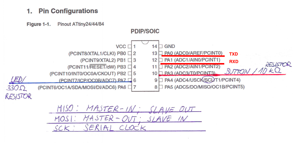
Furthermore, I describe on this sketch what the terms MISO, MOSI and SCK mean.
![]()
What problems I had ?
Sometimes my programmer from electronics production wasnt recognized by my computer. To solve this Problem, I pull the usb-cable out of my omputer and plug it in again. Furthermore my pc could not find the ftdi-cable at first. this problem I solved with the right driver for the ftdi-cable the prolific driver.
![]()
![]()
Software I used:
AVR DUDE is a command line tool with Functions include:
![]()
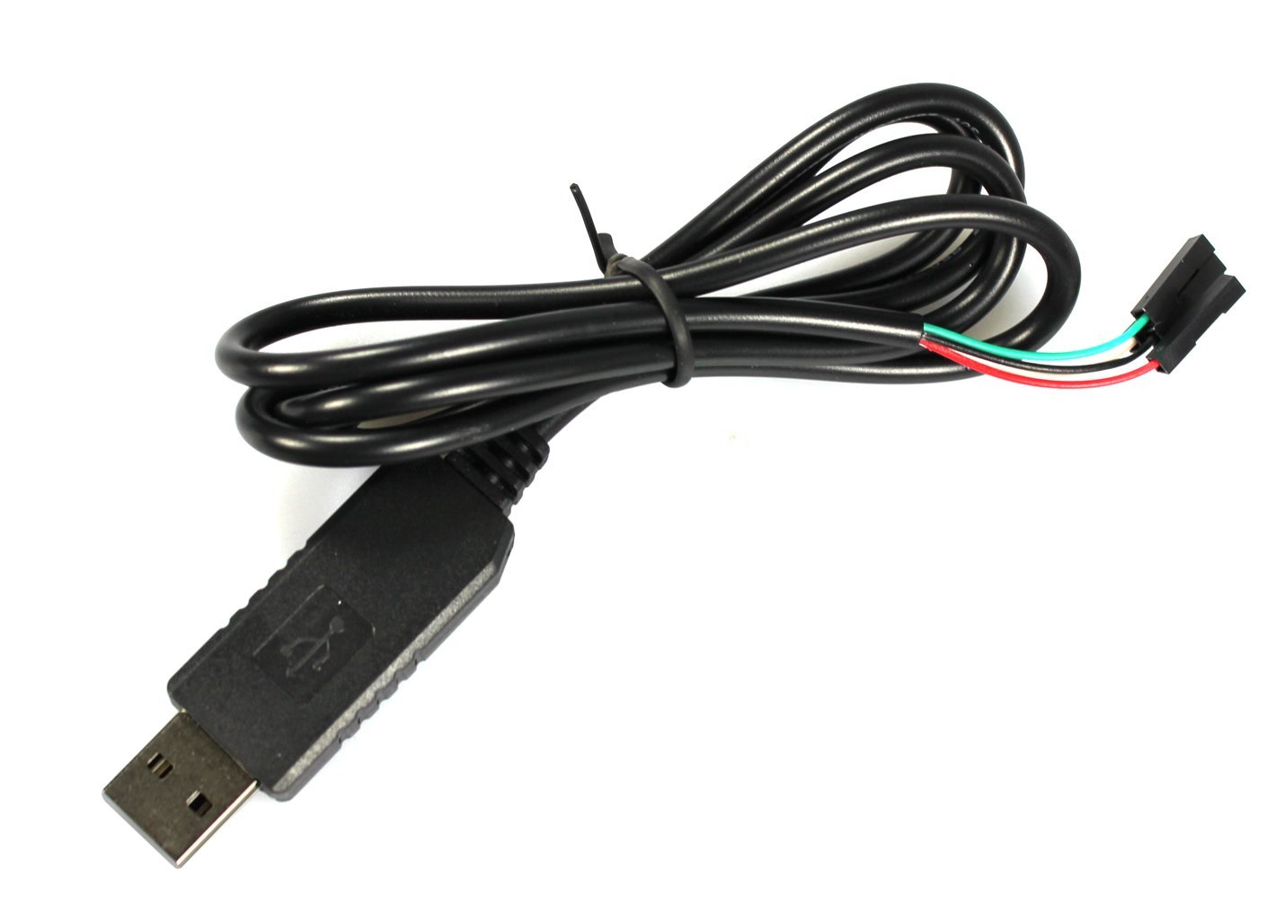
I ordered a cable a COM-FOUR PL2303HX USB zu TTL RS232 COM cabel-Modul Konverter to read the serial signal USB to TTL cable for 7 € from Amazon.
![]()
![]()
Programming the board:
![]()
The main.c for LED-Blinking example:
    //main.c AtTiny44 Program

#include  <avr/io.h>
#include <util/delay.h>

#define F_CPU 16000000
#define BUTTON_PRESSED	(PINA & (1<<PA3))		// check for button press
#define LED_ON	PORTA |= (1 << PA7)			// turn LED on code
#define LED_OFF	PORTA &= ~(1<< PA7)			// turn LED off code

typedef unsigned char  BYTE;
typedef unsigned short WORD;

void signal(){
	LED_ON;
	_delay_ms(500);
	LED_OFF;
	_delay_ms(500);
	LED_ON;
	_delay_ms(500);
	LED_OFF;
	_delay_ms(500);
	LED_ON;
	_delay_ms(500);
	LED_OFF;
	_delay_ms(500);
	LED_ON;
	_delay_ms(500);
	LED_OFF;
	_delay_ms(500);
	LED_ON;
	_delay_ms(500);
	LED_OFF;
	_delay_ms(500);
	LED_ON;
	_delay_ms(500);
	LED_OFF;
	_delay_ms(500);
	LED_ON;
	_delay_ms(500);
	LED_OFF;
	_delay_ms(500);
	LED_ON;
	_delay_ms(500);
	LED_OFF;
	_delay_ms(500);
	LED_ON;
	_delay_ms(500);
	LED_OFF;
	_delay_ms(500);
	LED_ON;
	_delay_ms(500);
	LED_OFF;
	_delay_ms(500);

}

int main (void) {
	// declare PA0 as output pin. This is where the motor and LED is connected
	DDRA = (1 << PA7);
	DDRA |= (1 << DDA3);	// using A3 as button input
	PORTA |= (1 << PA3);	// pull-up resistor


	// main loop
	while (1) {

		if (!BUTTON_PRESSED){
		   signal(0);
		}

	}
	return 1;
}
![]()
![]()
Video 2:
![]()
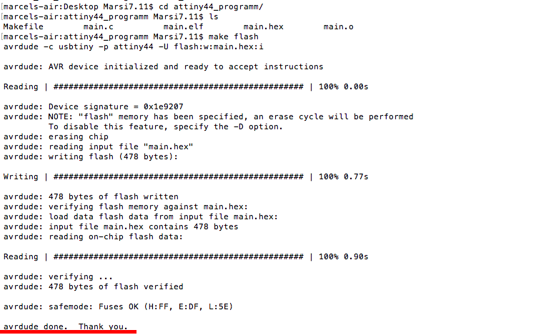
Go over the terminal into the directory in which the program file (Makefile and main.c you find in the download section) and the make file lies and type "make flash":
![]()
If at the end of the process "avrdude done. Thank you" (as marked as red appears), everything has been properly flashed on the chip
![]()
![]()
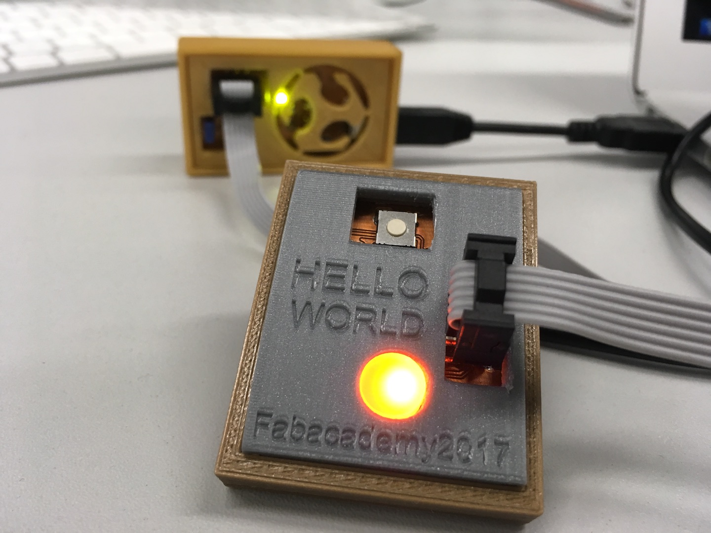
On the following photo you can see the self-made
fabISP for the first time in operation.
![]()
![]()
![]()
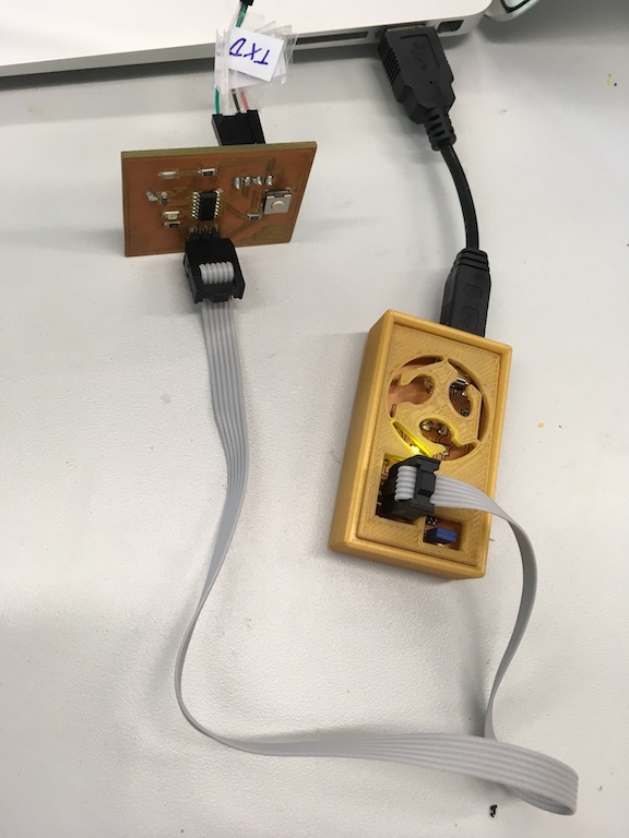
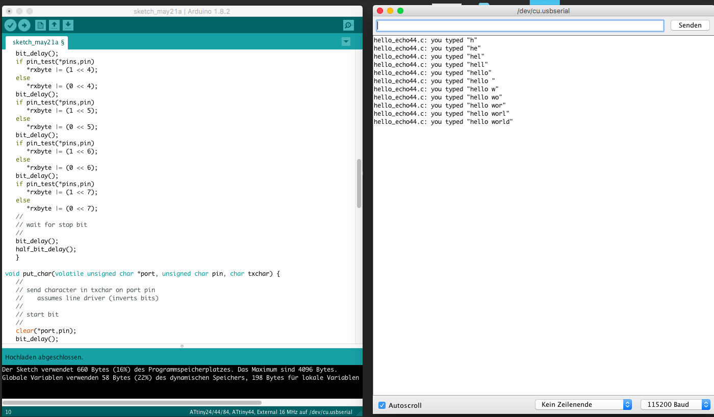
Programming hello-ftdi board
hello_echo44.c 115200 baud FTDI character echo
![]()
![]()
![]()
![]()
![]()
![]()
Modified sketch for hello_echo44.c 115200 baud FTDI character echo
//
#include <stdio.h>
#include <avr/io.h>
#include <util/delay.h>
#include <avr/pgmspace.h>

#define output(directions,pin) (directions |= pin) // set port direction for output
#define set(port,pin) (port |= pin) // set port pin
#define clear(port,pin) (port &= (~pin)) // clear port pin
#define pin_test(pins,pin) (pins & pin) // test for port pin
#define bit_test(byte,bit) (byte & (1 << bit)) // test for bit set
#define bit_delay_time 8.5 // bit delay for 9600 with overhead
#define bit_delay() _delay_us(bit_delay_time) // RS232 bit delay
#define half_bit_delay() _delay_us(bit_delay_time/2) // RS232 half bit delay
#define char_delay() _delay_ms(10) // char delay

#define serial_port PORTA
#define serial_direction DDRA
#define serial_pins PINA
#define serial_pin_in (1 << PA0)
#define serial_pin_out (1 << PA1)

#define max_buffer 25

void get_char(volatile unsigned char *pins, unsigned char pin, char *rxbyte) {
   //
   // read character into rxbyte on pins pin
   //    assumes line driver (inverts bits)
   //
   *rxbyte = 0;
   while (pin_test(*pins,pin))
      //
      // wait for start bit
      //
      ;
   //
   // delay to middle of first data bit
   //
   half_bit_delay();
   bit_delay();
   //
   // unrolled loop to read data bits
   //
   if pin_test(*pins,pin)
      *rxbyte |= (1 << 0);
   else
      *rxbyte |= (0 << 0);
   bit_delay();
   if pin_test(*pins,pin)
      *rxbyte |= (1 << 1);
   else
      *rxbyte |= (0 << 1);
   bit_delay();
   if pin_test(*pins,pin)
      *rxbyte |= (1 << 2);
   else
      *rxbyte |= (0 << 2);
   bit_delay();
   if pin_test(*pins,pin)
      *rxbyte |= (1 << 3);
   else
      *rxbyte |= (0 << 3);
   bit_delay();
   if pin_test(*pins,pin)
      *rxbyte |= (1 << 4);
   else
      *rxbyte |= (0 << 4);
   bit_delay();
   if pin_test(*pins,pin)
      *rxbyte |= (1 << 5);
   else
      *rxbyte |= (0 << 5);
   bit_delay();
   if pin_test(*pins,pin)
      *rxbyte |= (1 << 6);
   else
      *rxbyte |= (0 << 6);
   bit_delay();
   if pin_test(*pins,pin)
      *rxbyte |= (1 << 7);
   else
      *rxbyte |= (0 << 7);
   //
   // wait for stop bit
   //
   bit_delay();
   half_bit_delay();
   }

void put_char(volatile unsigned char *port, unsigned char pin, char txchar) {
   //
   // send character in txchar on port pin
   //    assumes line driver (inverts bits)
   //
   // start bit
   //
   clear(*port,pin);
   bit_delay();
   //
   // unrolled loop to write data bits
   //
   if bit_test(txchar,0)
      set(*port,pin);
   else
      clear(*port,pin);
   bit_delay();
   if bit_test(txchar,1)
      set(*port,pin);
   else
      clear(*port,pin);
   bit_delay();
   if bit_test(txchar,2)
      set(*port,pin);
   else
      clear(*port,pin);
   bit_delay();
   if bit_test(txchar,3)
      set(*port,pin);
   else
      clear(*port,pin);
   bit_delay();
   if bit_test(txchar,4)
      set(*port,pin);
   else
      clear(*port,pin);
   bit_delay();
   if bit_test(txchar,5)
      set(*port,pin);
   else
      clear(*port,pin);
   bit_delay();
   if bit_test(txchar,6)
      set(*port,pin);
   else
      clear(*port,pin);
   bit_delay();
   if bit_test(txchar,7)
      set(*port,pin);
   else
      clear(*port,pin);
   bit_delay();
   //
   // stop bit
   //
   set(*port,pin);
   bit_delay();
   //
   // char delay
   //
   bit_delay();
   }

void put_string(volatile unsigned char *port, unsigned char pin, char *str) {
   //
   // print a null-terminated string
   //
   static int index;
   index = 0;
   do {
      put_char(port, pin, str[index]);
      ++index;
      } while (str[index] != 0);
   }

int main(void) {
   //
   // main
   //
   static char chr;
   static char buffer[max_buffer] = {0};
   static int index;
   //
   // set clock divider to /1
   //
   CLKPR = (1 << CLKPCE);
   CLKPR = (0 << CLKPS3) | (0 << CLKPS2) | (0 << CLKPS1) | (0 << CLKPS0);
   //
   // initialize output pins
   //
   set(serial_port, serial_pin_out);
   output(serial_direction, serial_pin_out);
   //
   // main loop
   //
   index = 0;
   while (1) {
      get_char(&serial_pins, serial_pin_in, &chr);
      put_string(&serial_port, serial_pin_out, "hello_echo44.c: you typed \"");
      buffer[index++] = chr;
      if (index == (max_buffer-1))
         index = 0;
      put_string(&serial_port, serial_pin_out, buffer);
      put_char(&serial_port, serial_pin_out, '\"');
      put_char(&serial_port, serial_pin_out, 10); // new line
      }
   }
![]()
![]()
To also check the FTDI cable or a serial interface with a print function I have created in week 14 another fabkit, whereby I read the serialprint of a simple text with a baud rate of 57600 via the software Coolterm. If you want to learn more about coolterm and also what driver you need check my Week 13 - input devices.
![]()
![]()
![]()
Sketch for serialprint a text:
// the setup function runs once when you press reset or power the board
void setup() {
  // initialize digital pin LED_BUILTIN as an output.
  pinMode(LED_BUILTIN, OUTPUT);
  Serial.begin(57600);

}

// the loop function runs over and over again forever
void loop() {
  Serial.print("Hallo Welt!\n");
  digitalWrite(LED_BUILTIN, HIGH);   // turn the LED on (HIGH is the voltage level)
  delay(1000);    // wait for a second
  Serial.print("I bims, der FabKit vong Marsi her! \n");
  digitalWrite(LED_BUILTIN, LOW);    // turn the LED off by making the voltage LOW
  delay(1000);                       // wait for a second
}
![]()
Download-Section:
hello_echo44.c
main.c (blink example)
Makefile attiny 44
Hello world case
coolterm software
![]()
![]()
![]()