

Week 7 - Computer-Controlled Machining
![]()
![]()

![]()
![]()
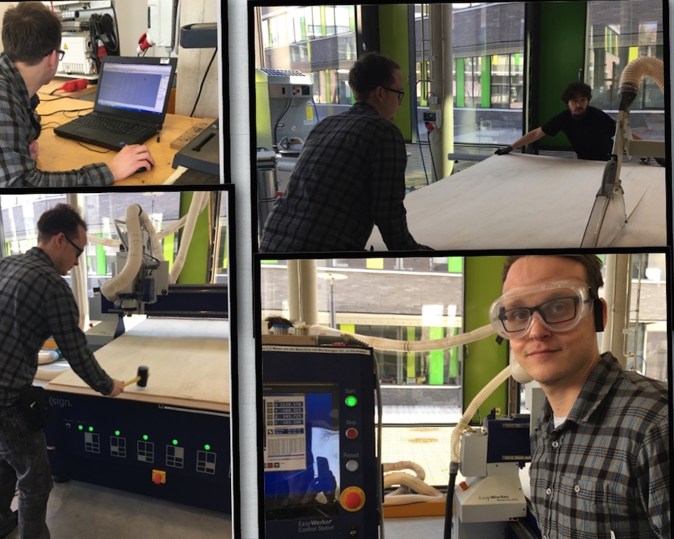
This week we should make something big
For that reason we went to our friends in Kamp-Lintfort to use the big CNC-mill
(Easyworker Master Pro 2513 ATC)
![]()
![]()
Safety Instructions
![]()
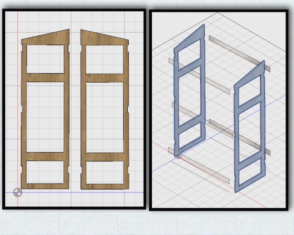
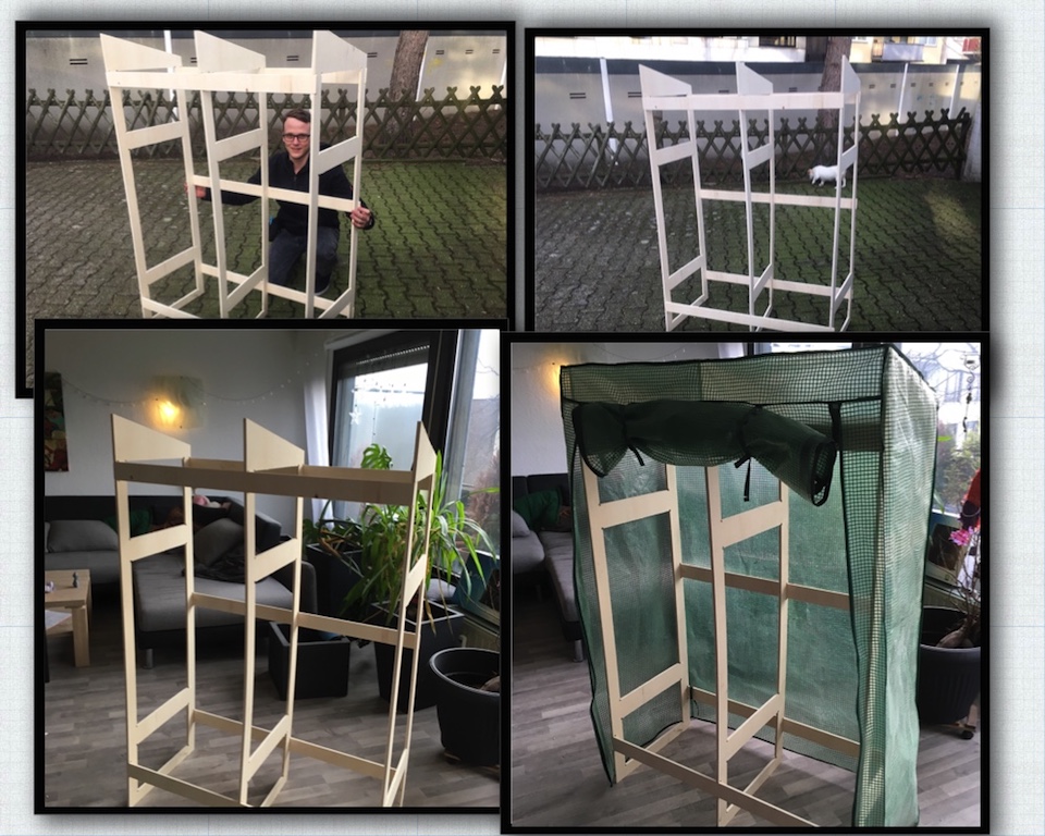
My wish was it to make a greenhouse for vegetables, because I have a balcony on
the south side and in summer it is the whole day sunny, which is perfect for a greenhouse.
My whole concept is based on a greenhouse, which I got at a hardware store
a while ago and from which I omly got the covering. But this time I wanted to make it more stable.
![]()
![]()
A short animation video of the joining component:
![]()
![]()
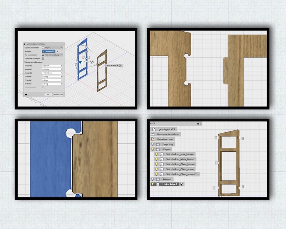
After measuring the cover, I made a suitable subconstruction for it in fusion360.
Since I'm working with wood, I had to consider that I have to paint my construction with a good amount of glaze to make it weather resistant.
![]()
![]()
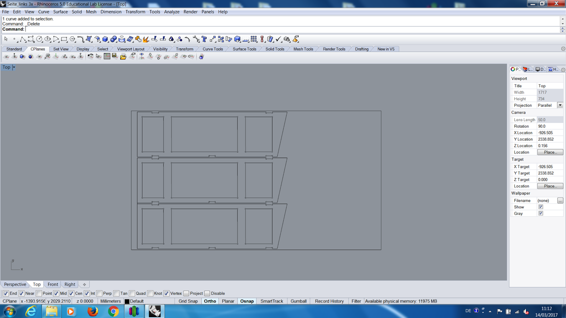
Every single object had to be converted to a sketch in fusion and had to be saved as .dxf file.
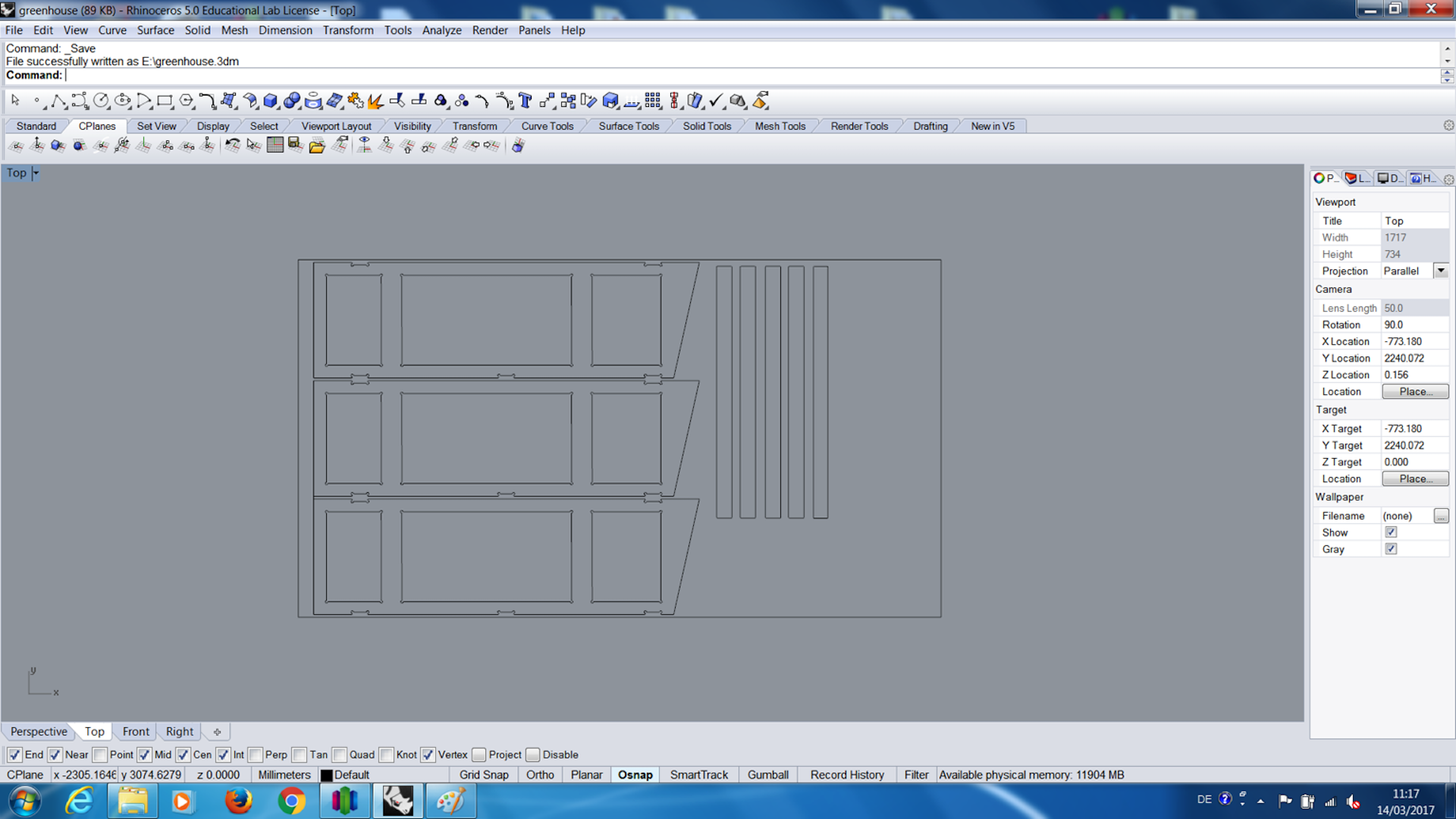
Through the kindness of Daniele, we could edit those .dxf files with the software Rhino so that all parts could be arranged
to fit in the machine bed. (only a few mm away from the border) Every was close to the border but it fitted well.
![]()
![]()
![]()
![]()
Firstly, the tailored wooden plank was placed onto the vaccuum table of the mill bed and adjusted with a try square.
While the vaccuum was sucking the plank in, I manually made sure that it layed plane on the bed, respectively the opferplatte by using my hand
and a soft face hammer.
![]()
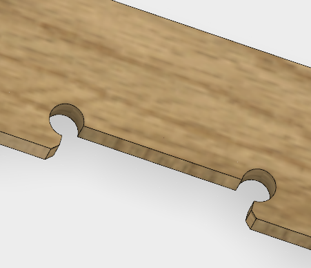
My Fablab Guru Daniele and my Instrucor Tobias told me in the regional review that I have to describe something more on the connecting elements and the vacuum table of the machine to complete this Assignment:
The connections are designed as on the pictures, because I work with the milling machine. The milling machine has to cut out various tools. In my case, I used 4mm end-mills, which always has a round coat surface. In order to clean the 90 degrees in the connecting element to achieve clean milling, the corner holes have been included in the design:
![]()
![]()
The vacuum table, the machine can be turned into various reach with the help of the buttons on the front of the machine, which is vacuumed for the milling machine through a mdx plate. Its very impressive that it could hold the workpieces while milling, becouse there are no holes in the mdx plate (the vacuum is strong enough). So it helps the workpiece to be machined, remains firmly on the machine while the rotating tool is milled (As you can see ob the pictures, there are 6 Buttons for different machine-portal areas).
![]()
![]()
![]()
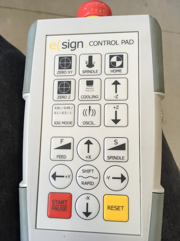
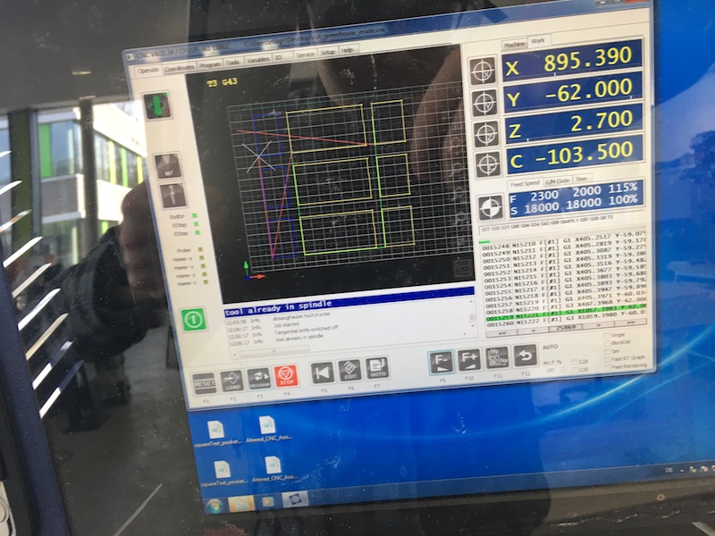
On the following picture you can see the controll panel with the red emergencystop-switch from the machine. During the entire milling process, you have to observe everything and, in case of emergency, press the red emergencystop-switch button to avoid injuring persons and/or the machine:
![]()
I followed Neils advice and executed the mill job at first in the air (x = 0, y= 0 z = cut in the air) whithout cutting the material, to see if everything is really fitting and more importantly, to see that I won't cause crashes with the tool.
After that was done, I started with milling:
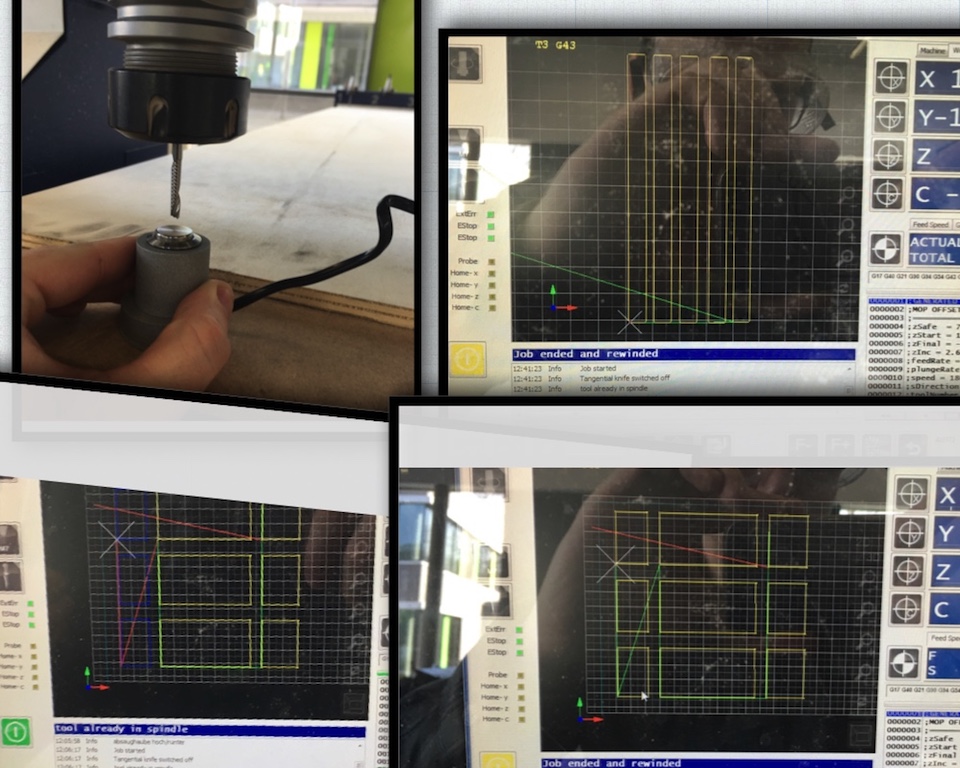
The mill, respectively the surface was putted on zero by me moving the milling head on anexternal device (see photocollage further down).
The workpiece is tensioned by a vacuum table on the machine. Through the buttons we will put the whole vacuum into operation (6 Buttons for different machine-portal areas) and deep delivery in 3 stages.
1. First, the inner parts of my design were made, which took ca. 30 min at 1400 mm/min. The reason for that is that the outer parts,
which could be important for the design, are not able to move.
2. Outer cuttings (the connecting elements of the sides). That took ca. 20 min.
3. Another outside cut which took ca 30 min (The whole outer silhouette with the height difference and the angle).
Altogether the mill moved 4 times over the milling path at 10mm thickness to cut through the wood.
![]()
The mill, respectively the surface was putted on zero by me moving the milling head on an external device. CAM program showed the actual status:
![]()
![]()
While milling, the CAM program showed the actual status like the routing of the traces and remaining time, the positions, generated toolpaths and the actual used code:
![]()
![]()
After I have entgrated the wood parts, I could then put them together. For this I did not need a wood glue. All parts fits perfectly togheter. Since the greenhouse still stands in my apartment, it is not exposed to the weather. As soon as it comes onto the balcony, it is still glued to the reinforcement of the connecting elements and lacquered with a weather-resistant paint.
![]()
![]()
Postscript/Additions:
Set the parameters according to the material and tool(s) I use. Show the relation between what material I use and the spindle speed, feed, doc I choses.
First of all, I would like to mention that here the calculated values are mostly far from the reality. You can calculate everything, but do not go beyond experience. If you hear at certain feed speeds that the machine "strange" sounds, we know that something is wrong (the values listed are for a rough orientation and may deviate from the table depending on the machine and periphery).
![]()
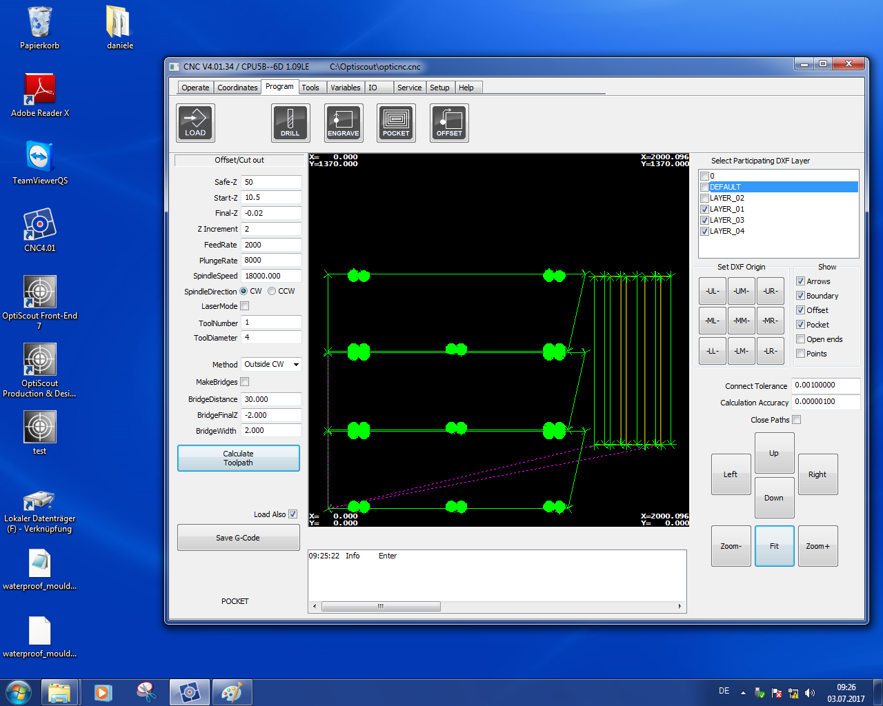
The program settings are set:
For Material thickness of 10 mm:
-----------------------------------
Safe-Z = 50
Start-Z = 10.5
Final-Z = -0.02
Z Increment = 2
FeedRate = 2000
Plunge Rate = 8000
Spindle Speed = 18000
Spindle Direction = CW (becouse we use a right hand end mill)
Tool Number: 1
Tool Diameter: 4
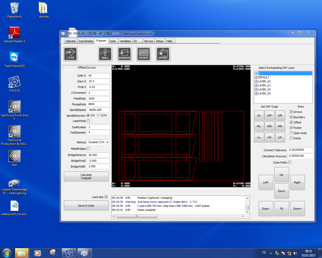
Method: Inner CW for inner cut and Ousite CW for outer cut.
Bridge Distance: 30
The z increment is roughly the half of the diameter of the tool, and that we used one flute tool which make smooth surface with our wood. We go -0,01 as final-z for cut through everything
![]()
Please find the useful formulas here
Example-Values:
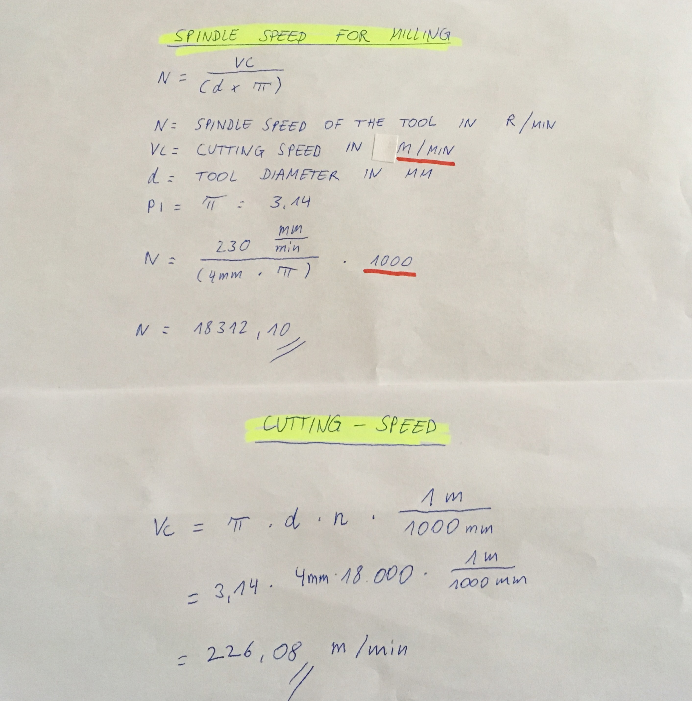
The speed for milling is calculated using the following formula:
D = cutter diameter in mm Pi = circle number (3.14)
My instructor gave me a cutting speed for wood to calculate the speed given. This is 230 m / min. He told me that this is a good value for orientation for this type of wood:
![]()
The cutting speed is the speed with which the tool cutting on the workpiece.
For my Greenhouse-parts I open the DXF-files again in the milling terminal:
![]()
Outside-cut Clockwise (Method: Outside CW):
![]()
Inside-cut Clockwise (Method: Inside CW):
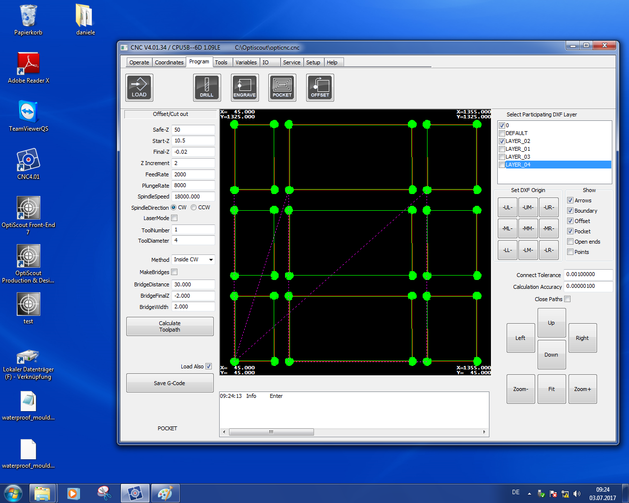
![]()
The entire job:
![]()
![]()
Feed Rate
=
RPM
∗
Chip Load
∗
Number of Flutes
![]()
![]()
After all parameters are double-checked. Click on the toolpath to calculate, save the G code and the software will change the user interface to the automatic mode.
The milling operation is ready to start for the inner tracks. Check the maximum Z height of the machine, turn on the extraction for the dust and make sure that nothing is not moving and the vacuum bed is working well.
![]()
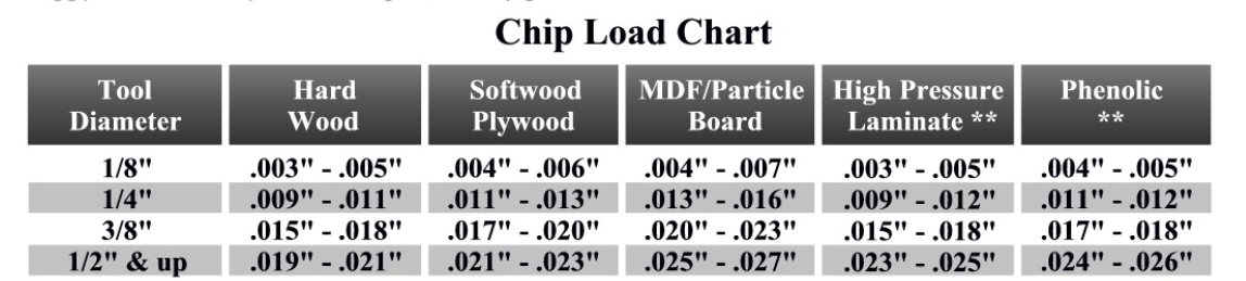
Please also do the calculations about “feed” and write down the difference between the two:
![]()
Speeds/Feeds:
![]()
The Feedrate is the speed that the tool moves through a workpiece. With the Z-Increment, the Feedrate depends on the kind of material and the tool in use. There exist tables and lists where you can find different feedrates for different materials and tools.
A too fast feed rate can damage the workpiece. A too slow feed rate can cause a recoil.
![]()
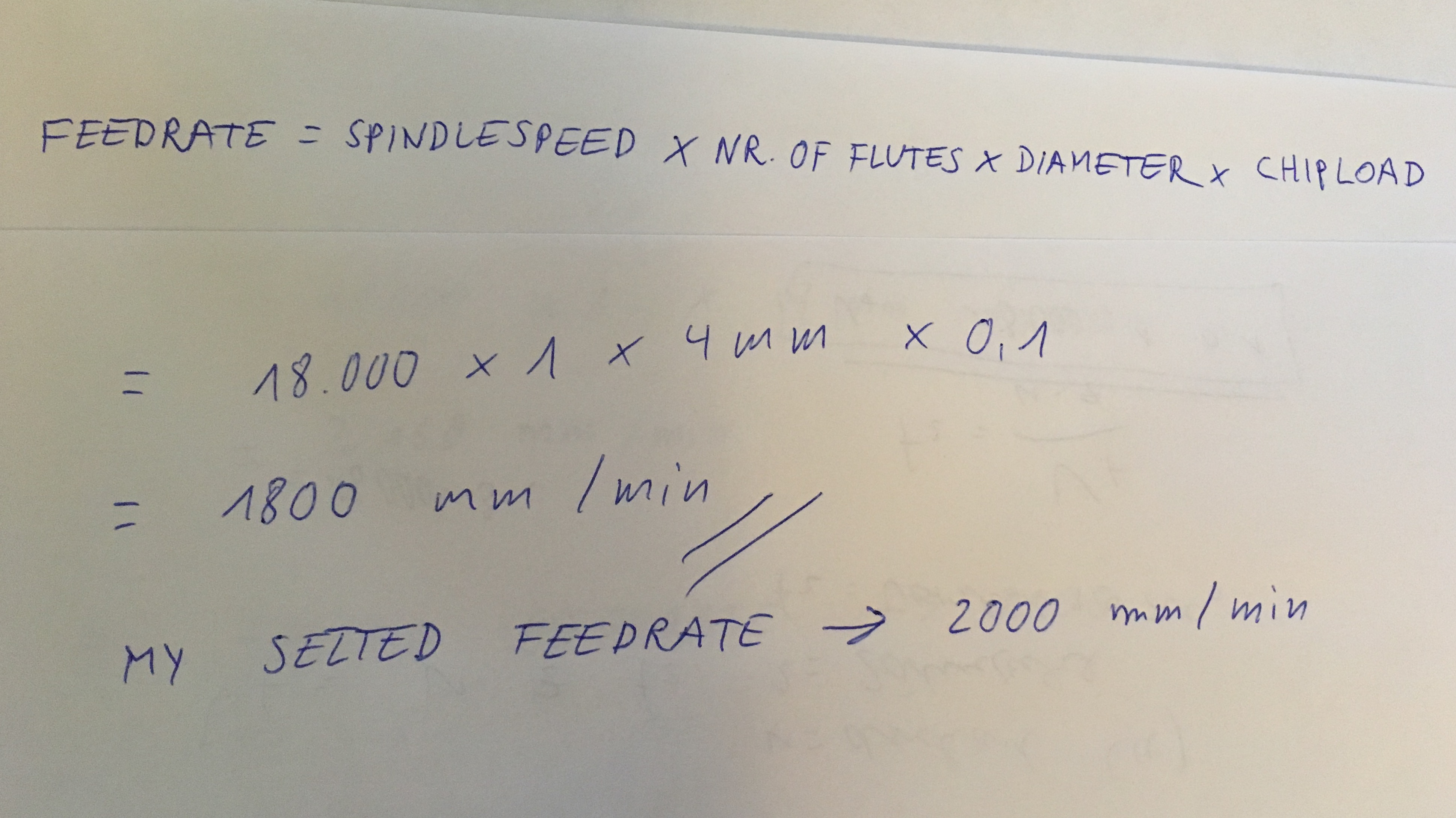
Calculation of the Feedrate:
ChipLoad x CutterDiameter x NumberOfFlutes x SpindleSpeed = FeedRate
Calculation of feed rate:
![]()
![]()
Download-Section:
Greenhouse_Part_1
Greenhouse_Part_2
Greenhouse_Part_3
Greenhouse_Part_4
![]()
![]()
![]()
![]()
![]()
![]()
![]()
![]()