FABACADEMY 2017

Final Project - Electronics

HRW OpenHydroponicGrowbox

  • First Ideas
  • Concept and Germination-tests
  • Build the Box and the nutrientsolution-container
  • 3D-Prints
  • Electronics
  • Software
  • Putting it all togheter
  • Testing and Conclusion
  • Summary
  • Control-units

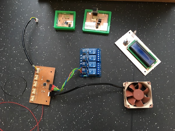
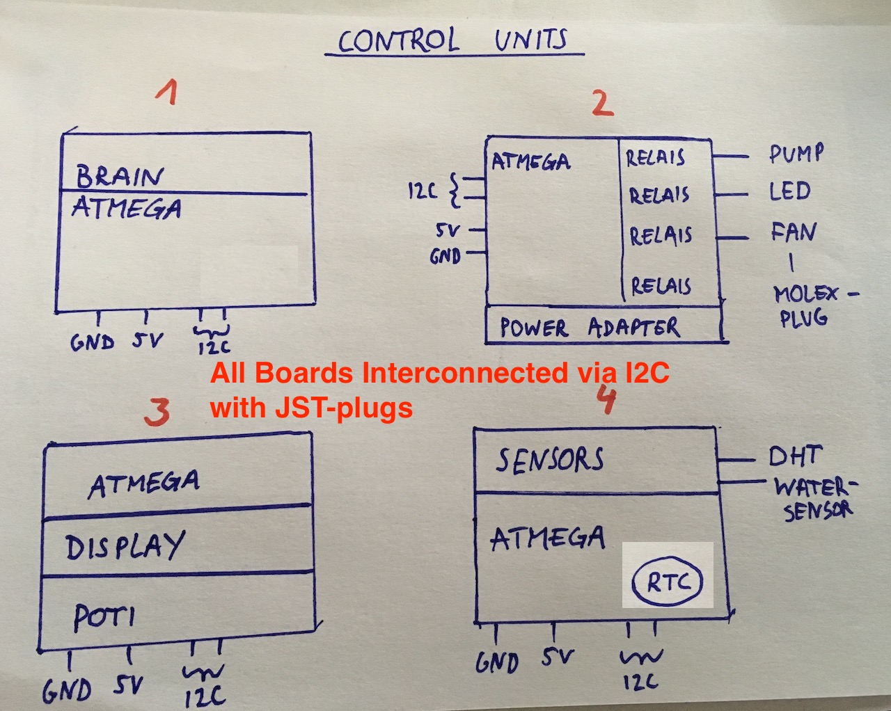
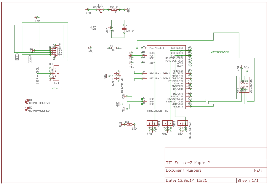
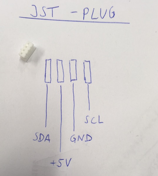
    4 handcrafted pcbs are milled, which are interconnected via I2C-bus with 4,7 kΩ Pullup resistors on SDA and SCL pin.

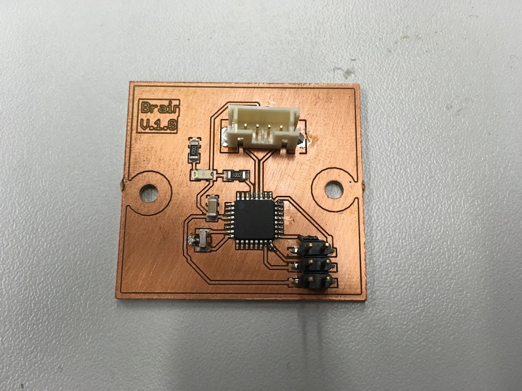
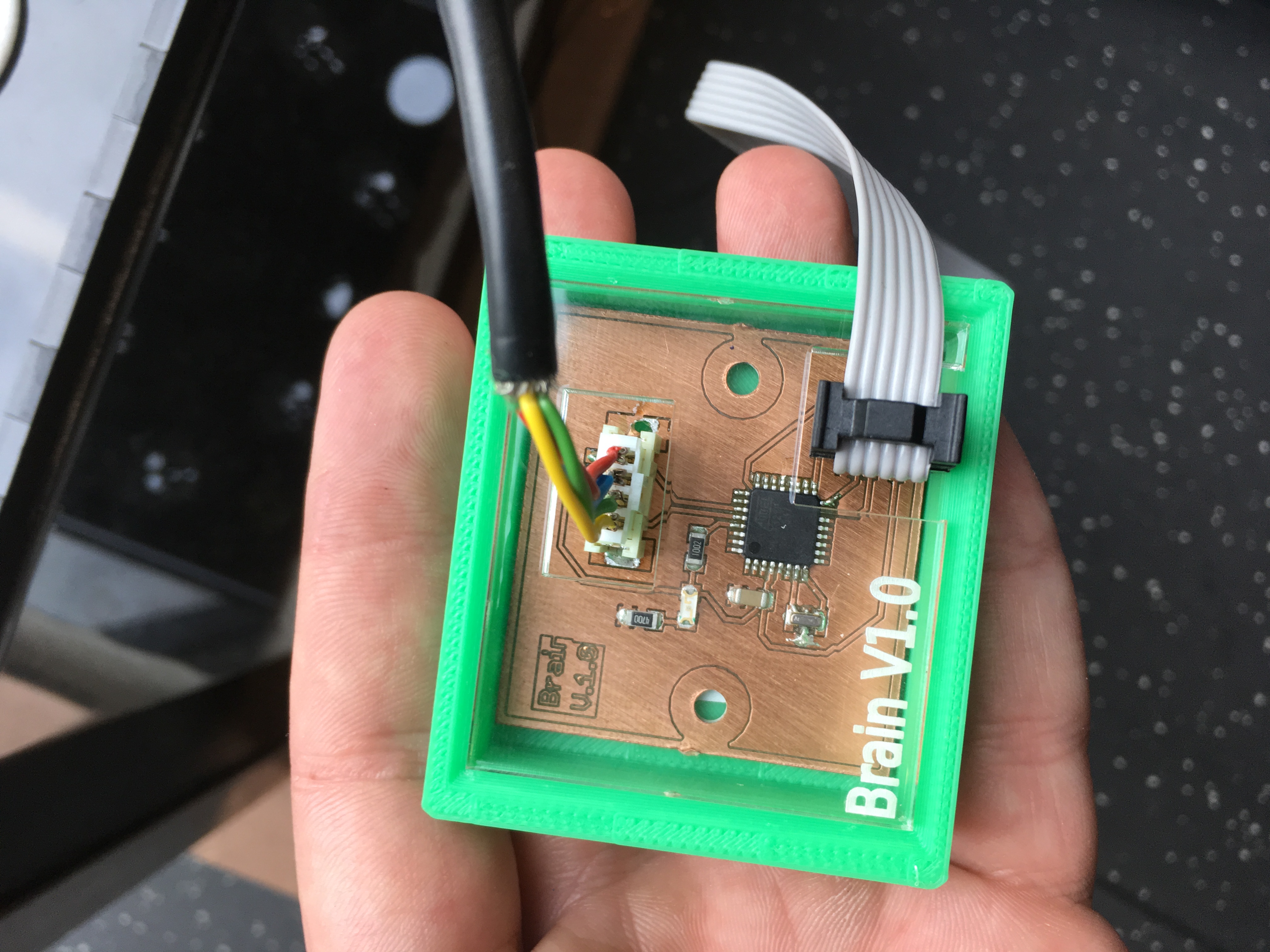
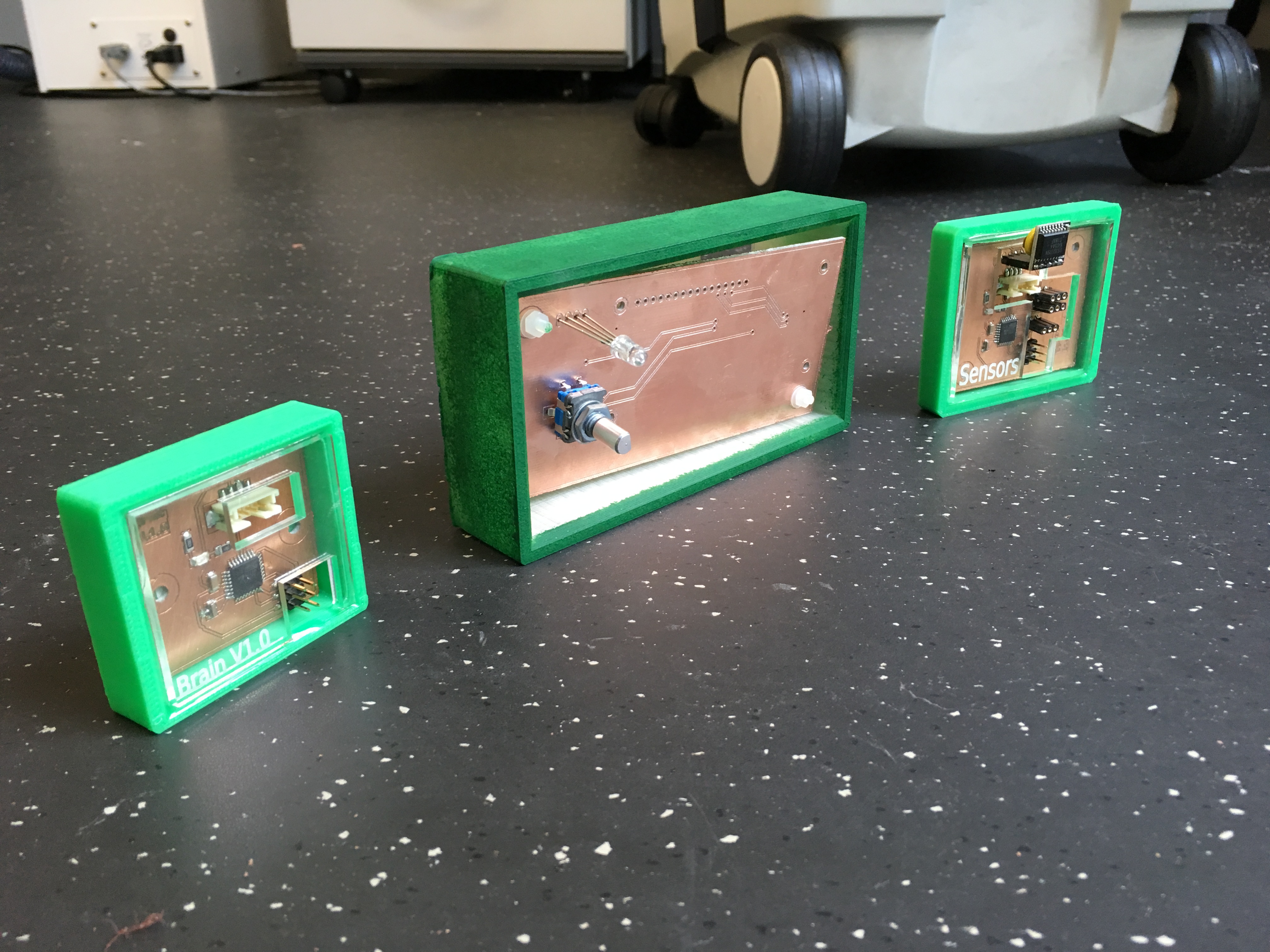
  • The first board (controll-unit 1 - MASTER) is called "The Brain" and is the master board.
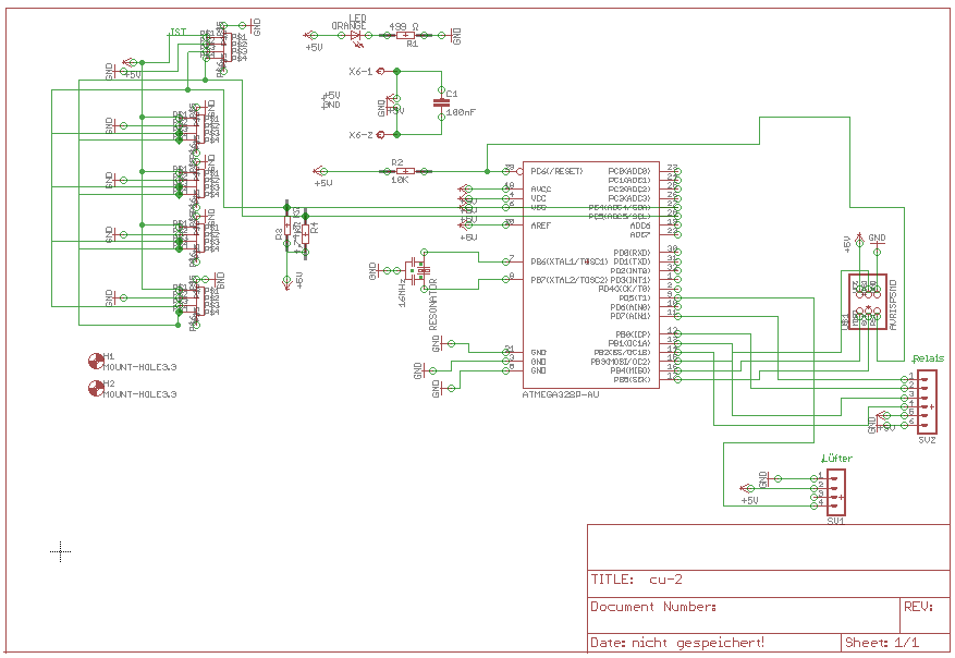
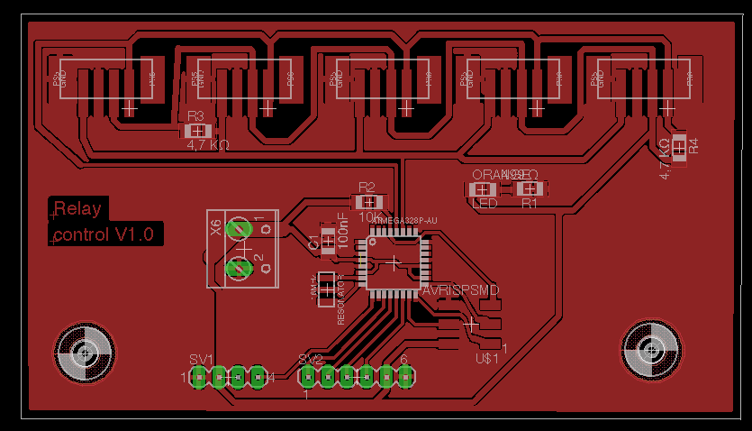
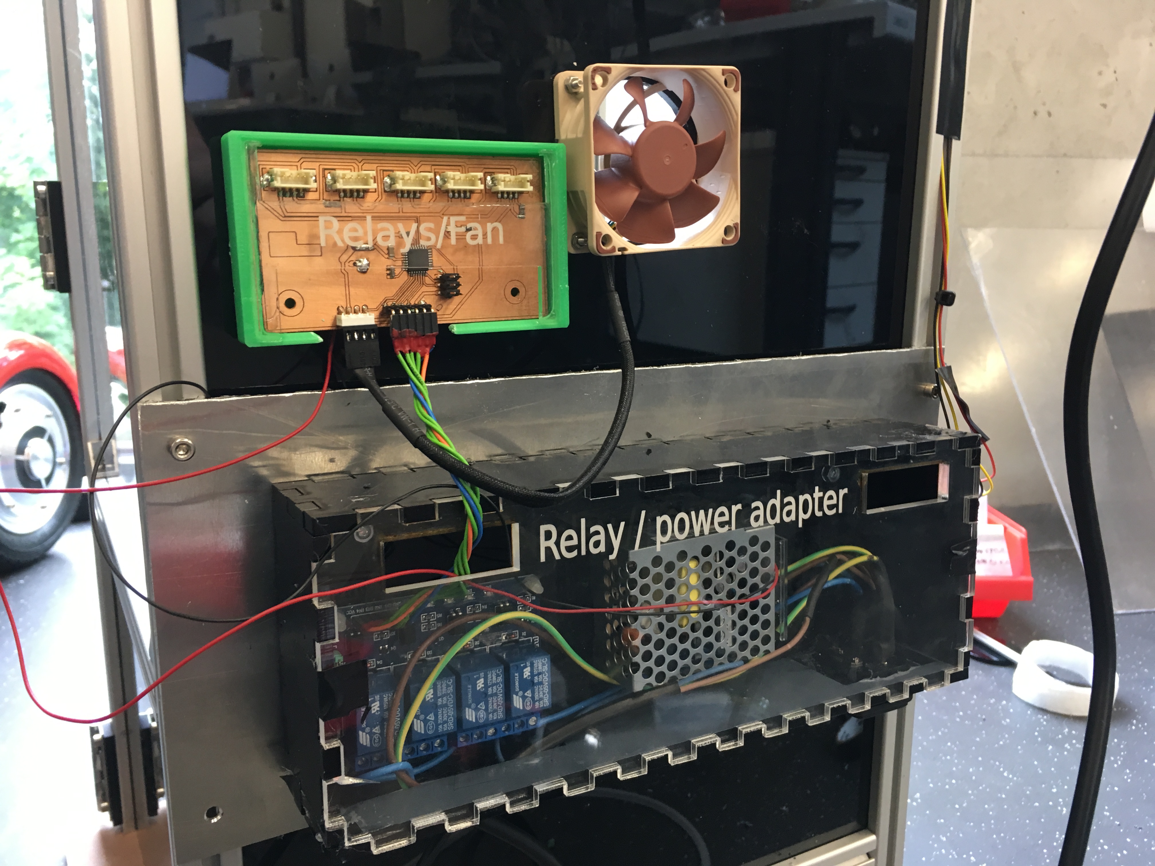
  • The second board (control-unit 2 - SLAVE#1) is called the relay-control and can switch the Output devices (LED, the pump and the fan).
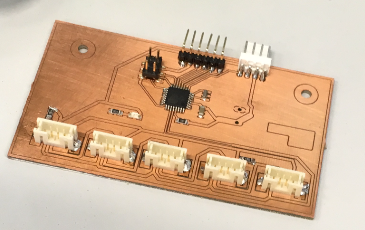
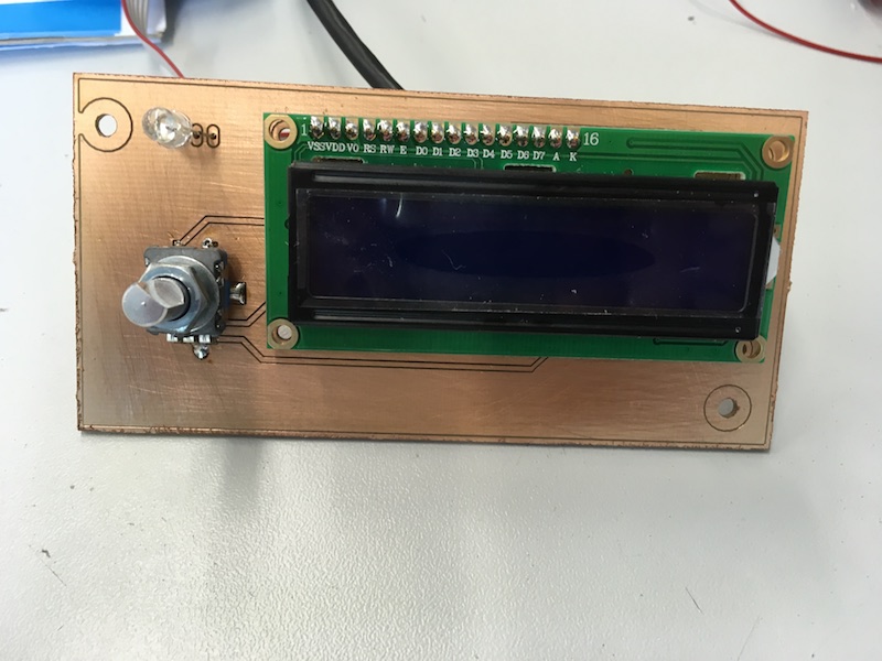
  • The third board (controll-unit 3 - SLAVE#2) is the input Interface-board, on which a Encoder-pushbutton, a rgb-LED and an lc display.
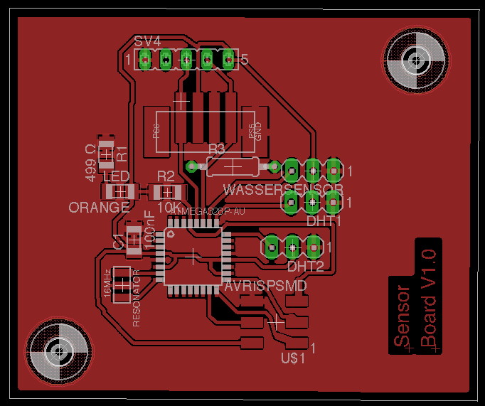
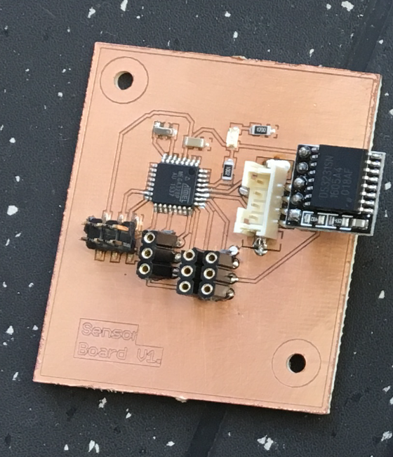
  • The fourth board (controll-unit 4 - SLAVE#3) is the sensor or "input board" on which the waterlevelsensor, a Real Time Clock and the DHT temperature/humidity sensor are installed.
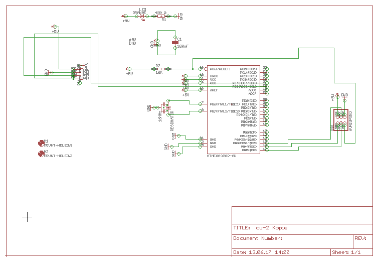
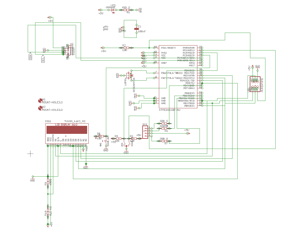
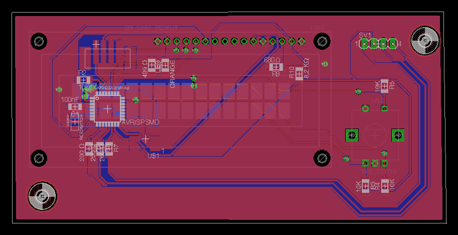
  • An ATmega 328 P-AU is installed on each of these boards.

    List of all used Components:

  • 4 self made PCBs (with ATmega 328 P-AU) milled and equiped in our FabLab
  • 5-Pin D Schaft 20 Nummern Detents 360 Grad Rotary Encoder with Push Button
  • Link
  • 1602A LC-Display
  • Link
  • Noctua NF-A6 x 25 PWM-Fan 60 mm A 3000 U A 5 Volt
  • Link
  • LED-Pflanzenleuchte Lampe für Pflanzen mit 45 Watt und 225 LEDs
  • Link
  • Europet Bernina 264-111420 6200cc - Hi-Tech Air Membranpumpe - max.370 Liter/ 2 Outputs
  • Link
  • 5mm Roundhead RGB LED
  • Link
  • 5V/220V 4 Channel Optocouplers Relay Shield for Arduino Optokoppler Relais Modul
  • Link
  • Switching power supply, 15W, 3A, 5V
  • Link
  • DaoRier DS3231 AT24C32 Real Time Clock RTC High Precision Clock Modul IIC Modul-Speichermodul
  • Link
  • DHT22 Digital temperature-and humidity-Sensor-Modul AM2302
  • Link
  • Humidity sensor module 1 pc SE045 Iduino
  • Link
  • JST and Molex Plugs and a 500 mA Fuse
  • Control-unit 1 - Brain/Master board:

    Eagle schematics:

    Eagle layout:

    Milled and equiped:

    Here you can see the interfaceboard in the 3d printed housing (more datails at Putting it all togheter)

    Download Eaglefiles brainboard.zip

    Control-unit 2 - Relay-control/ Slave board):

    Eagle schematics

    Eagle layout

    Milled and equiped:

    Download Eaglefiles relayboard.zip

    Control-unit 3 - Interface lcd-board/ Slave board (double sided pcb):

    Eagle schematics

    Eagle layout (Double-sided pcb)

    Milled and equiped:

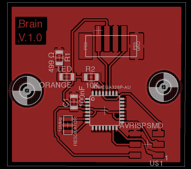
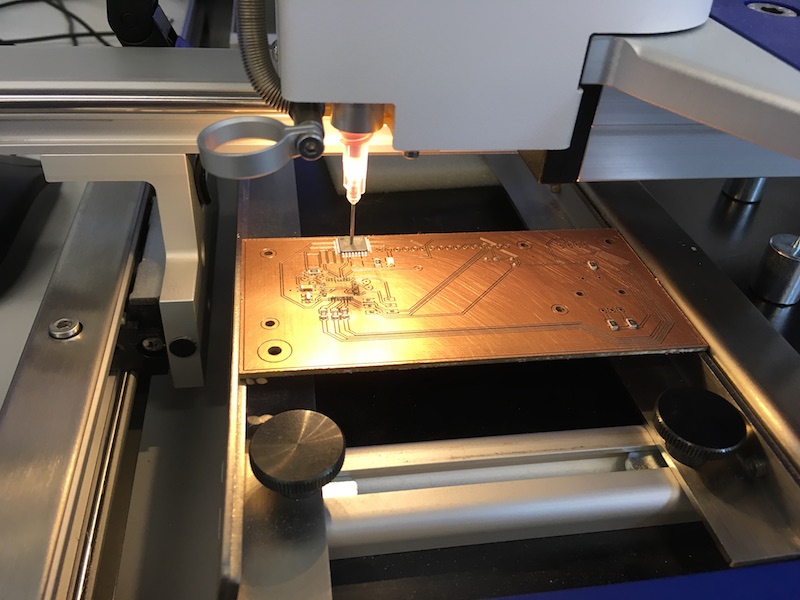
    For this pcb I make a video while milling, becouse it was my first double-sided pcb. 4 reference holes are drilled on the upper side. The autofocus camera of the LPKF machine recognizes these holes, after the board has turned over. By means of this orientation, the machine can continue the conductor tracks on the back. Really impressive technology!:

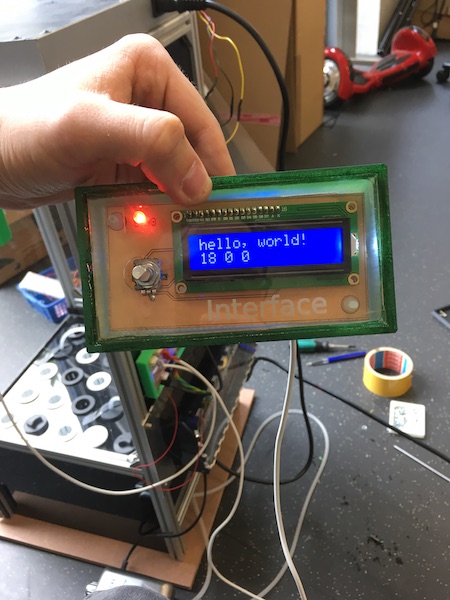
    Here you can see the interfaceboard in the 3d printed housing running an example programm (more datails at Putting it all togheter)

    Download Eaglefiles displayboard.zip

    Control-unit 4 - Sensor/Real Time Clock-board/ Slave board):

    Eagle schematics

    Eagle layout

    Milled and equiped:

    Download Eaglefiles sensorboard.zip

    Here you can see the ready integrated pcbs ind cd printed housings with engraved acryl lids:

    Here you can see some more of the system integration of the power supply and the relay-unit with the relay-control pcb and the fan:

    Here you can see the wire shematic for the jst-plugs:

    Back to top of page

    back to index