Machine design
Week 10's assignment
- Laser cutter for the structure
- CNC mill for the FabNet
- 3D printer for the tap system
- One Arduino board and One raspberry Pi to control the "l axis"
- Material :
- 5mm cardboard and 5mm plywood
- PLA
- Software :
- Rhino for the design of the machine and the 3D parts
- Cura for the 3D printed parts
- Atom for programming
- Arduino IDE for arduino sketches
- Other equipment :
- Silicon tubes
- Plastic taps (for acquarium aeration systems)
- Plastic connectors (for acquarium aeration systems)
The assignment :
Make a machine, including the end effector,build the passive parts and operate it manually,
document the group project and your individual contribution.
The idea
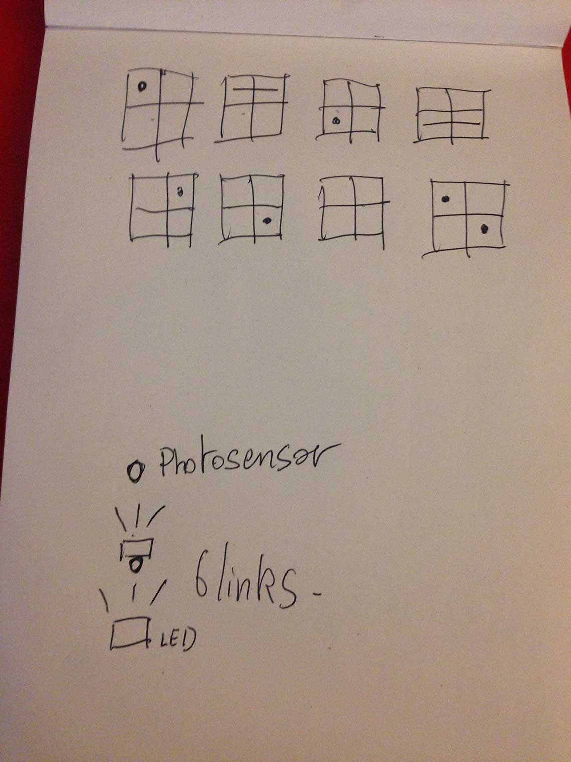
First thing we had to do as a group was of course to all agree on an idea for the machine. We decided to individually think of one idea and then to share them and decide which one would be selected. So here is an overview of the sketches that where proposed by the group :Guillaume's electronic music maker :
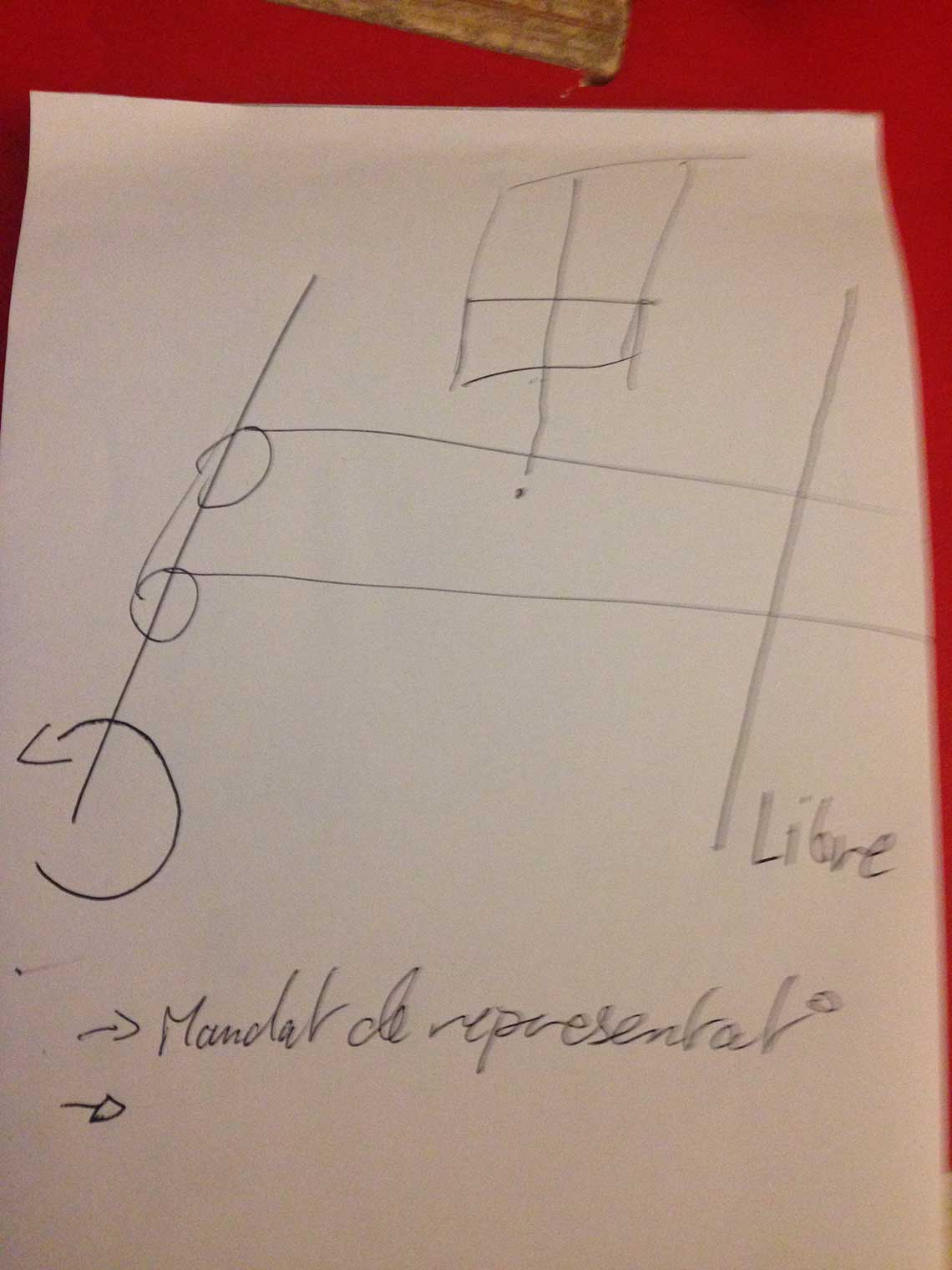
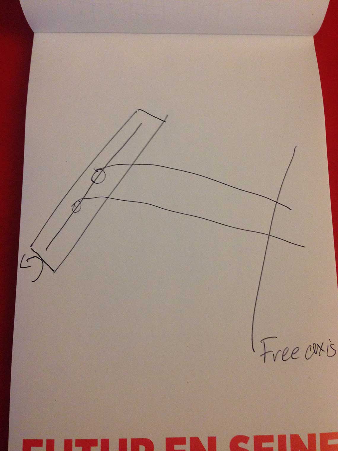
My idea : a drawing machine :
Ludovic's cocktail maker :
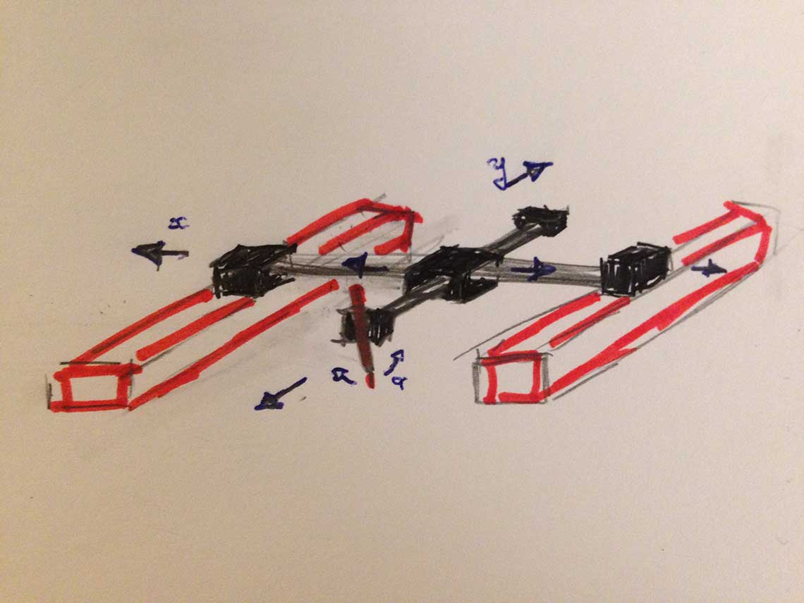
Roman's version of the cocktail maker :
 In Roman's version, the bottles are positionned with the head down and the idea is to use servo-motors to open and close the circulation of the fluids in the hoses.
Frederic's version of the cocktail maker :
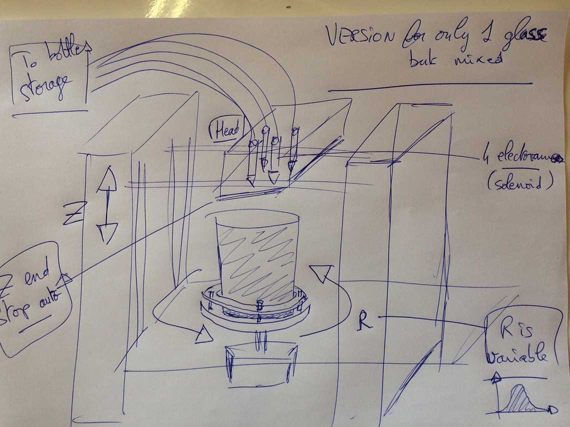 Frederic proposed a version where there would be only on glass placed on a rotative bed. A variable rotation would be applied to act as a shaker.
And so without any surprise and after a very short concertation, the winner is : The Cocktail Maker.
It will be a machine that prepares shooters, just like your favourite barman does !
 We will still have to find a proper name for it, but it will come later.
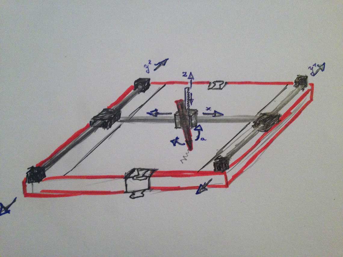
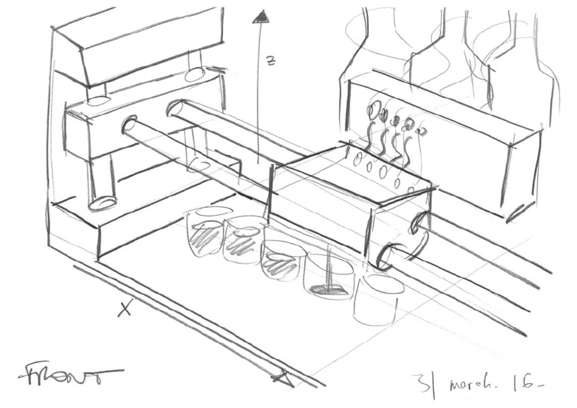
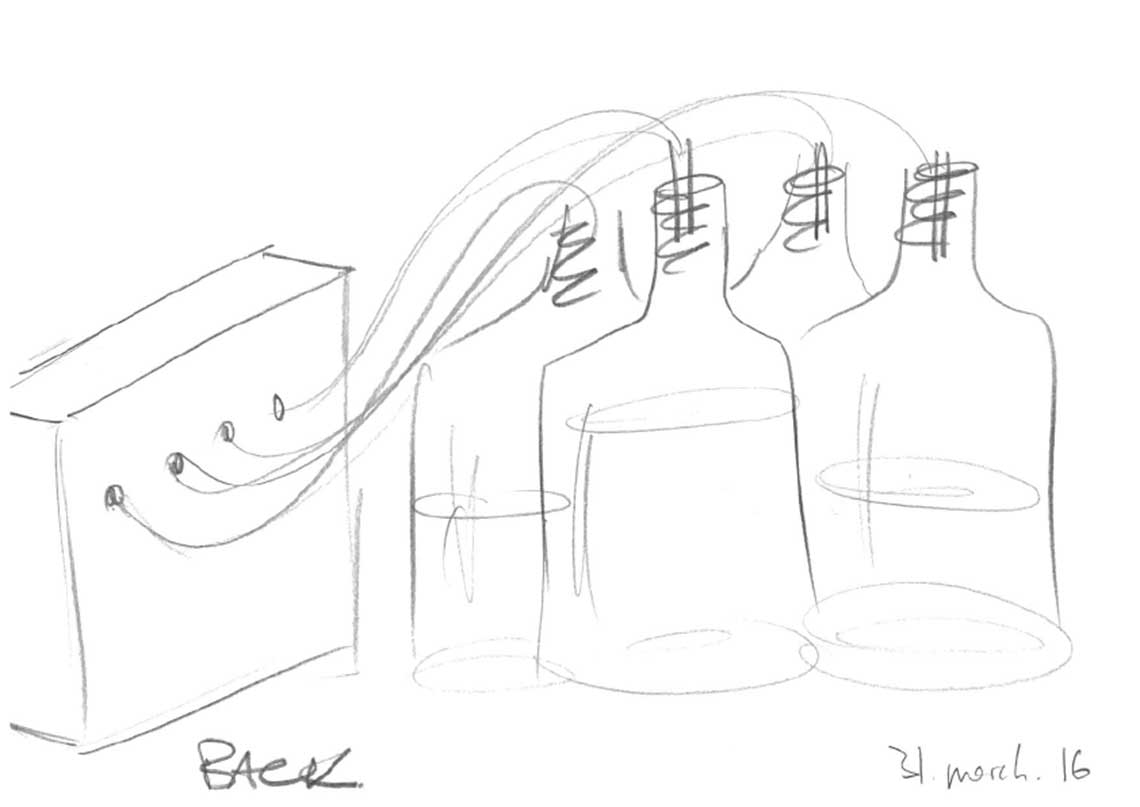
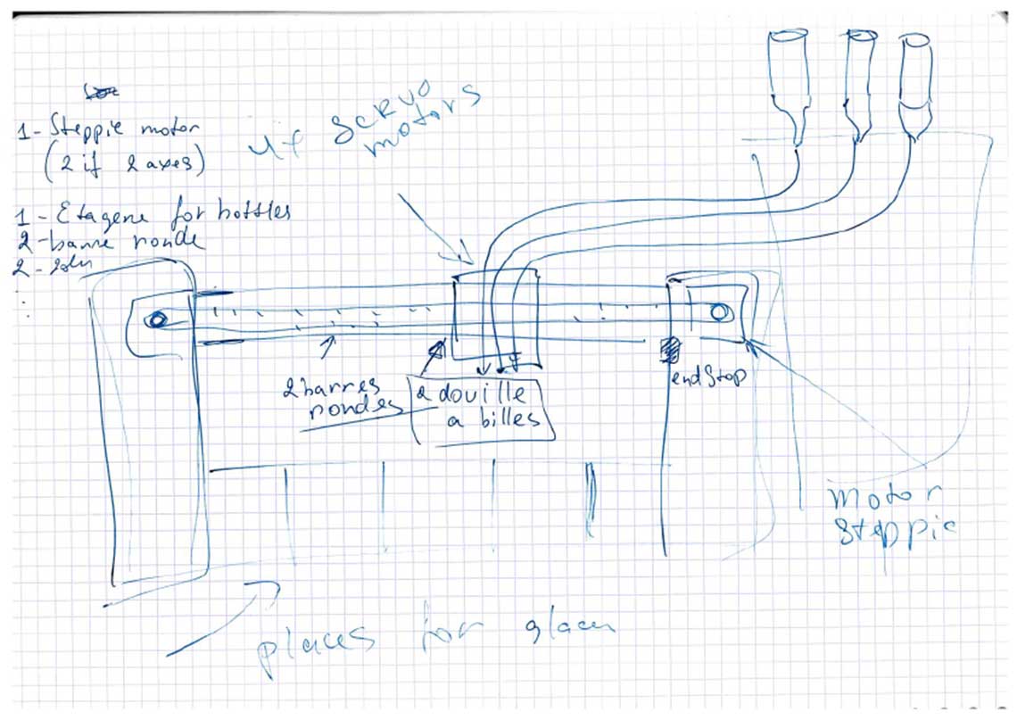
Here is the final sketch that we did together to agree on the general structure and mechanism :
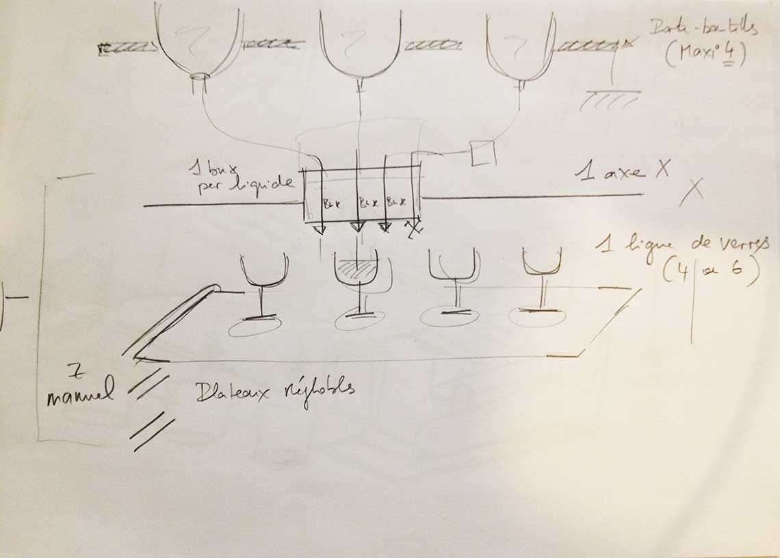
Main notes about the machine :
- The machine serves shooters, mixing different beverages directly into shot glasses
- Each bottle is connected to the head (lets say there are 4 of them) and has its own extruder
- The bottle will be disposed with the head down like in Roman's design and we will use solenoid valves for the distribution of liquids
- For the moment we will only use one axis, X, to move the nozzle horizontaly (and we will add an other one later I we have time)
- The glasses we be disposed in one raw (or several raws if we decide to use a Y axis)
- The glasses will be placed on a removable bed standing on a multi-level rack. This way we will be able to manually modify the Z. Also, the bed can act directly as a tray for serving the shooters.
1. Make the model of the machine
2. Build the prototype
3. Design the electropnics
4. Write the code
5. Create the interface
6. Document the project for the group
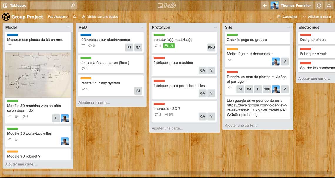
Each of these topics we be subdived in different tasks that we have to determine. For this, we will be setting up a Trello board to organize our work efficiently. According to the skills and expertise of each member of the team, we will then be able to complete this table :
| Student | Task |
|---|---|
| Frédéric | Fluid mechanics |
| Guillaume | Prototyping and programmation |
| Ludovic | 3D model of the machine |
| Roman | Programmation, electronics |
| Me | Documentation, 3D model of the machine |
| Vincent | Documentation, prototyping |
 The entire group project is detailed here. This is the page I was in charge of.
Before beginning the design, we took the time to measure each element included in the kit that we have received, which was essentiel to design a suitable structure.
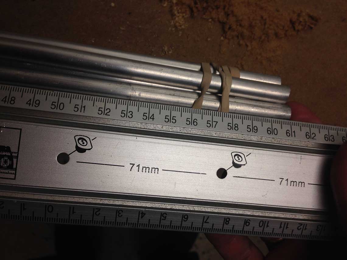 It was especially important because we realized that the shafts were by 10cm larger than they were in the model file provided for the assignement. So we would also have to redising the whole wrapping structure for the motor and the nozzle.
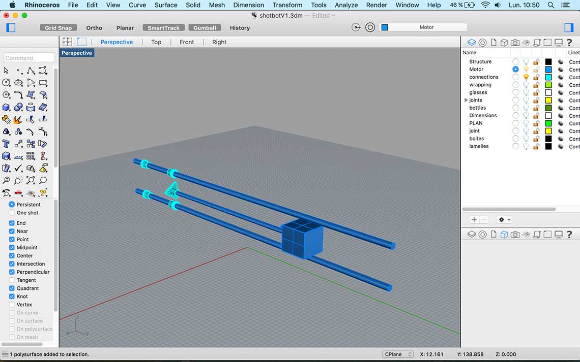
I began with this part because the motor and the shafts were the elements that would determine the dimensions of the whole structure :
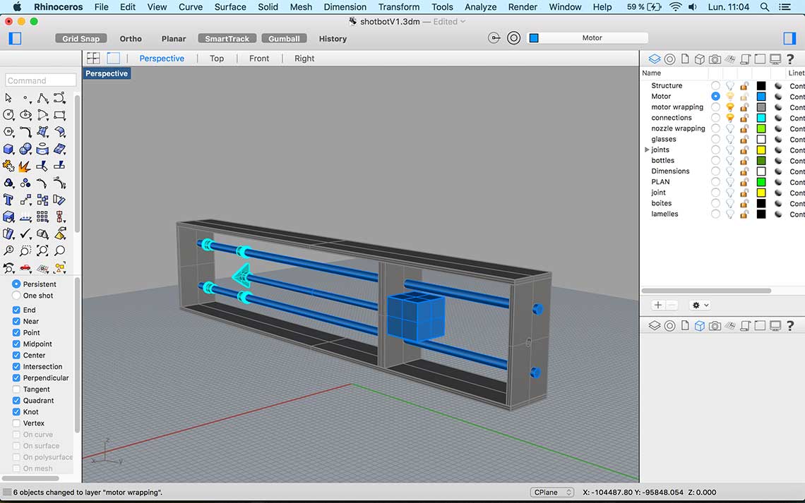 Then I was able to build the structure, making it as stable as possible. Note that we chose to begin by designing a 3D model first, to have a good overview, and we picked a 5mm thickness because we wanted to work with cardboard, plywood or MDF that we would laser cut, rather than using the CNC mill which not available very often at the lab these days.
Once the main structure was made, I could continue with the bottle stand...
Then I was able to build the structure, making it as stable as possible. Note that we chose to begin by designing a 3D model first, to have a good overview, and we picked a 5mm thickness because we wanted to work with cardboard, plywood or MDF that we would laser cut, rather than using the CNC mill which not available very often at the lab these days.
Once the main structure was made, I could continue with the bottle stand...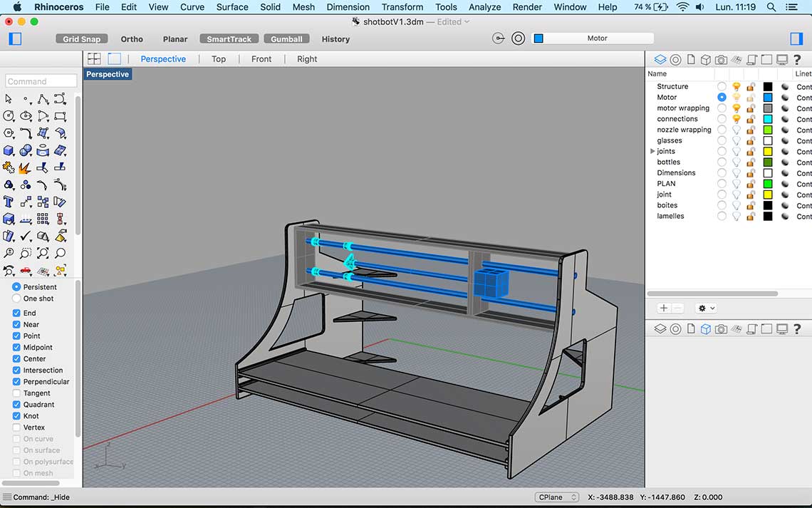 The best way to do it was for me to model the bottles from measures I took on real liquor bottles :
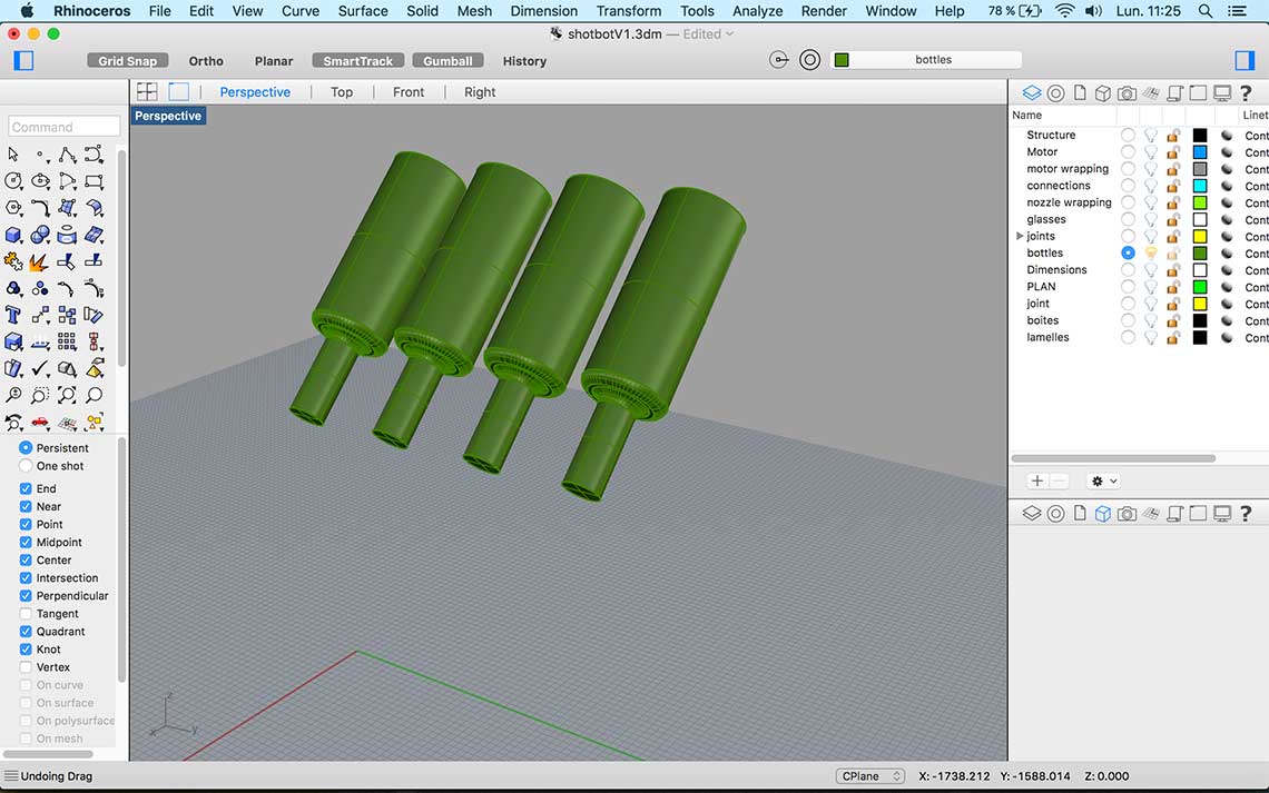 From this it was easy to design a stand for the bottles, attached to the main structure for more stability :
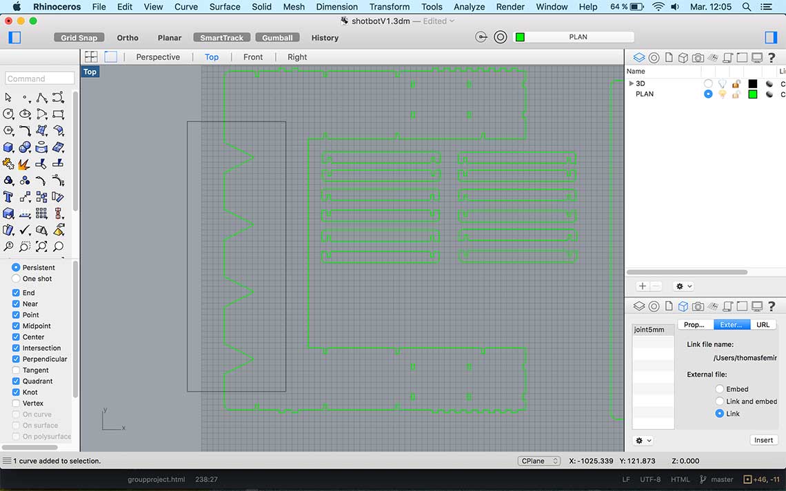
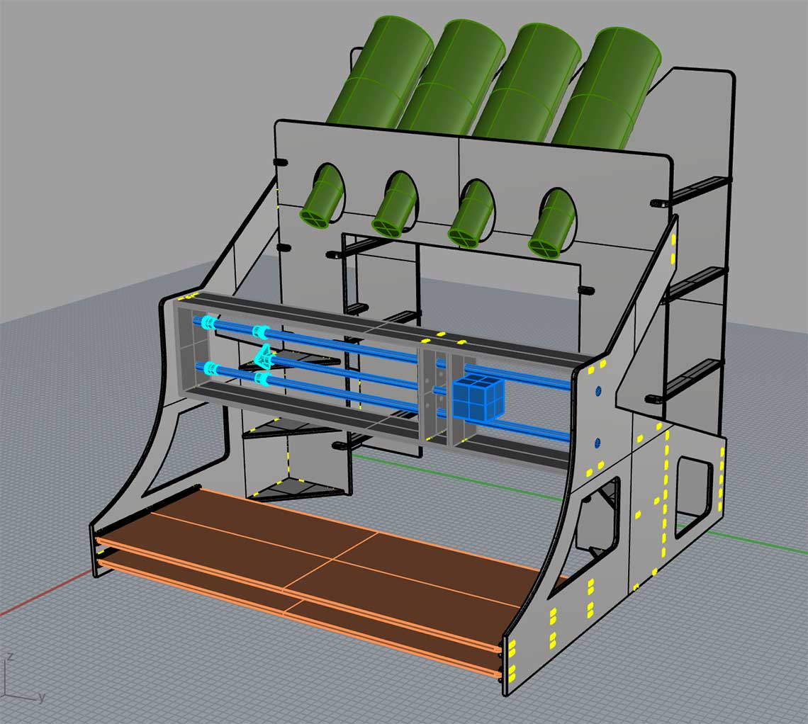 The design phase being completed, I prepared the file for the cut. All the parts fit on 3 700x990mm sheets :
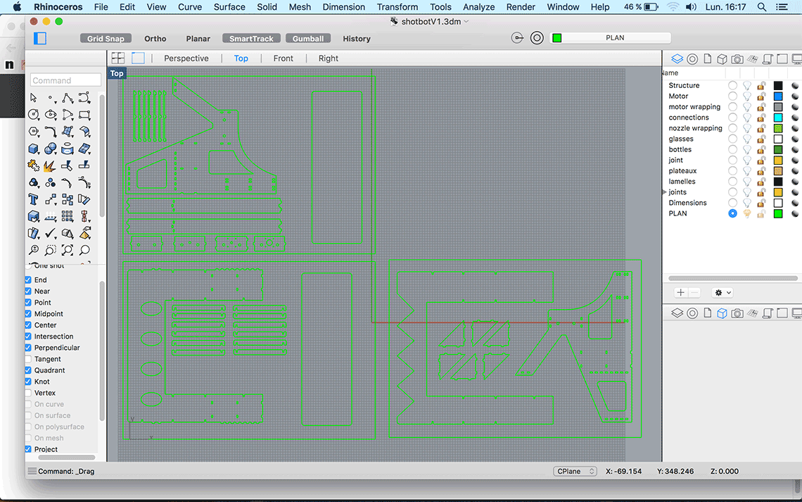 Then we laser cut the parts. Unfortunately the laser cutter at Woma was not available due to maintenance so we had to go to Vincent's Lab. But it turns out that their laser cutter was acting quite strange so we spent a lot of time trying to get the right configuration and did not really succeed. It turned out that the bad was not completely flat and also that the lens seemed quite unfocused so the cut was not clean and the cardboard was burned in some parts.
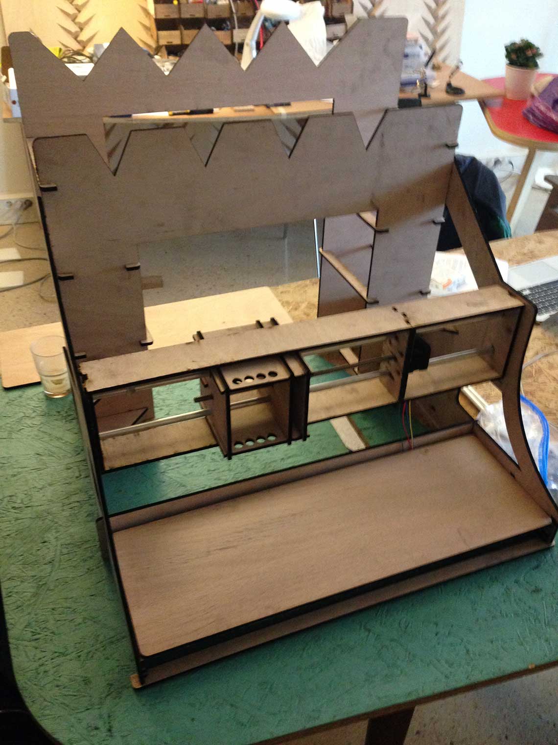
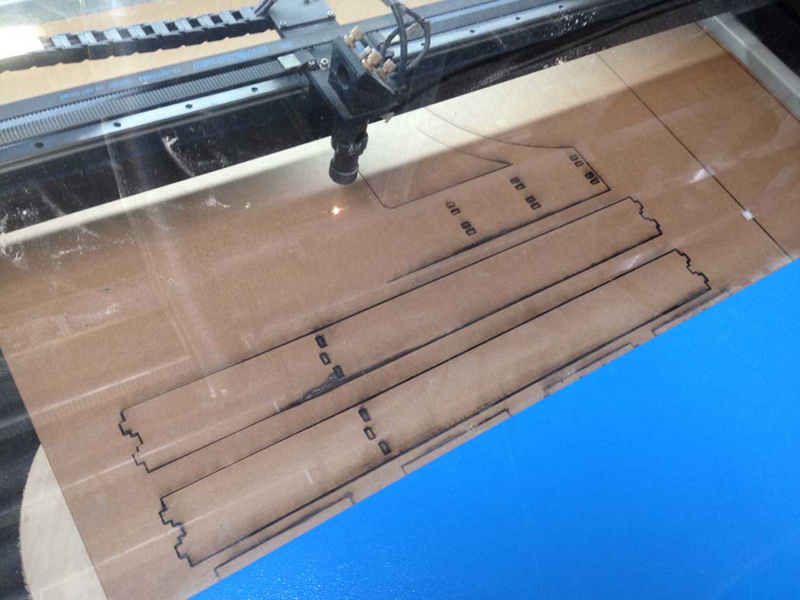 We managed to get all the parts cut anyway but we had to do a lot of hand cut (using a cutting knife). Then we assembled the parts together and voilà ! :
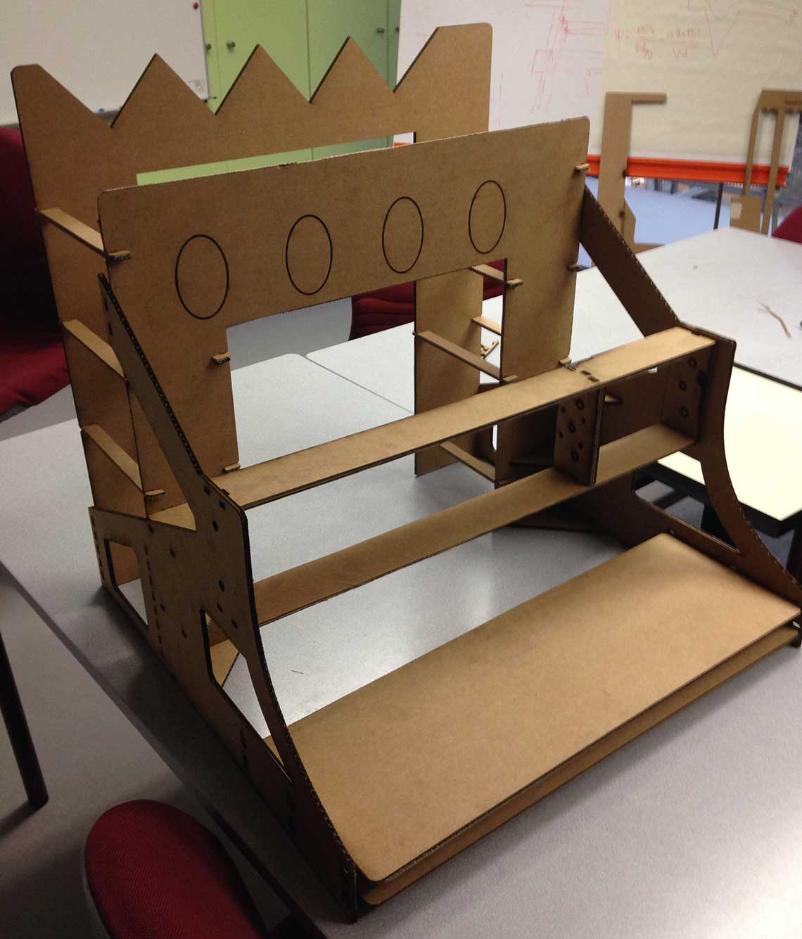 Generally the structure was OK and pretty stable but I decided the next version would have to be made of a stronger material such as plywood. I also noticed a few things that could be improved. Here the connecting teeth were missing in the cut file:
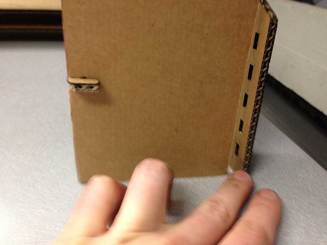 Here I decided to add to "bridges" (in yellow) to reinforce the front of the structure : One bellow the trays, and one behind them.
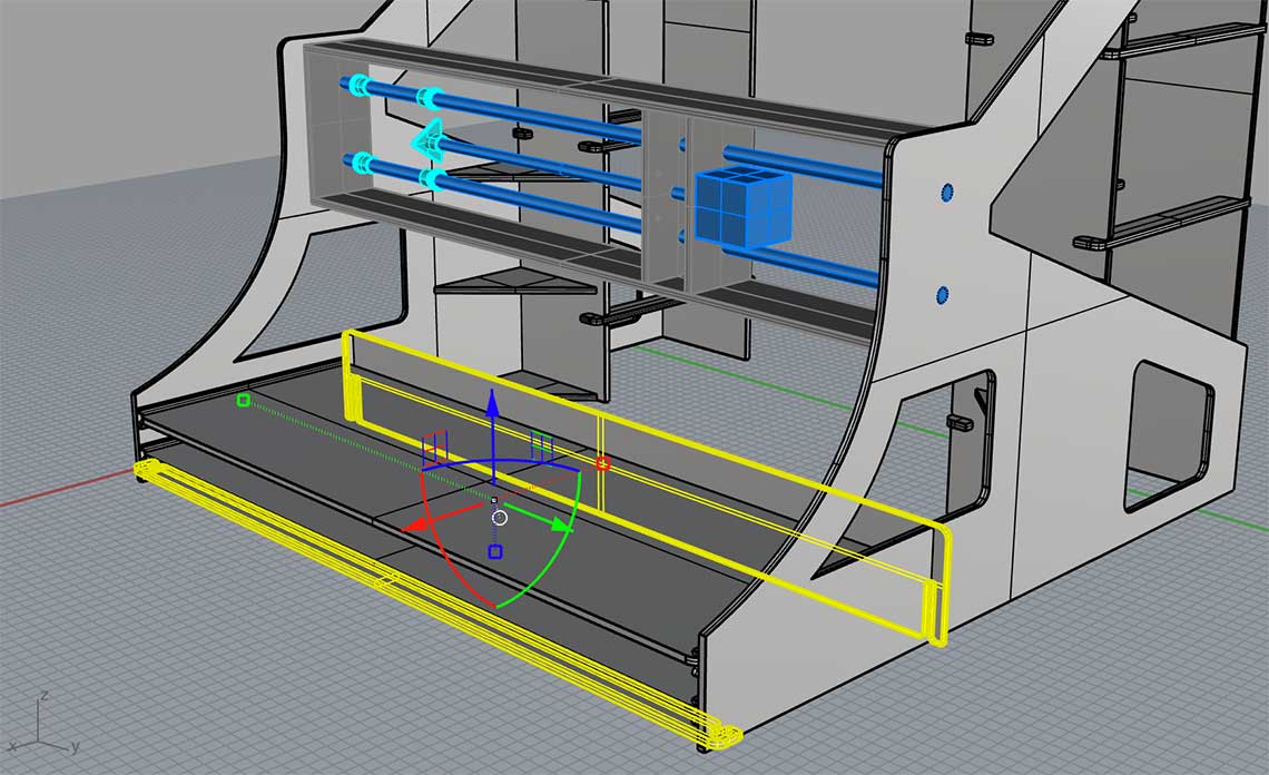 Finally I re-designed the bottle stand because we did a rapid test with a whine bottle and realised the front holes where too large and too low :
 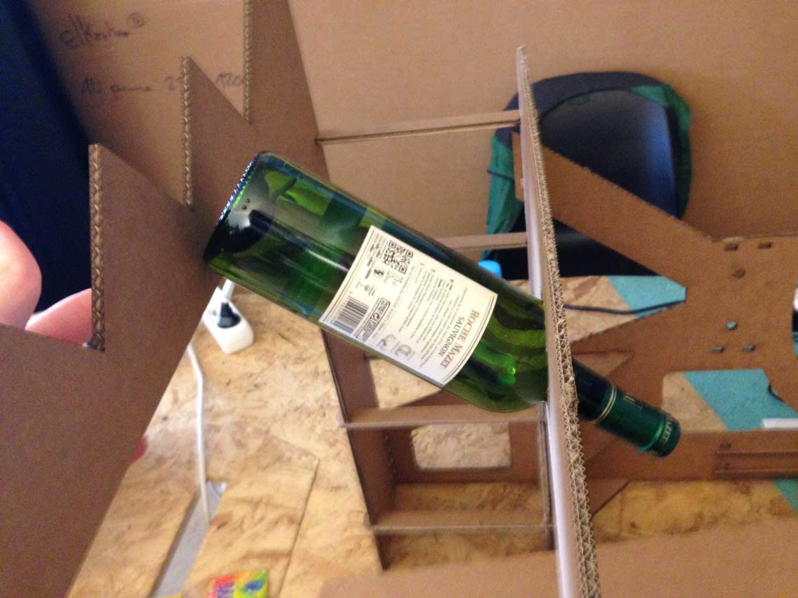 So instead of holes, I reproduced the same triangular shape on the front part of the stand, like this (did it directly on the cut paths) :
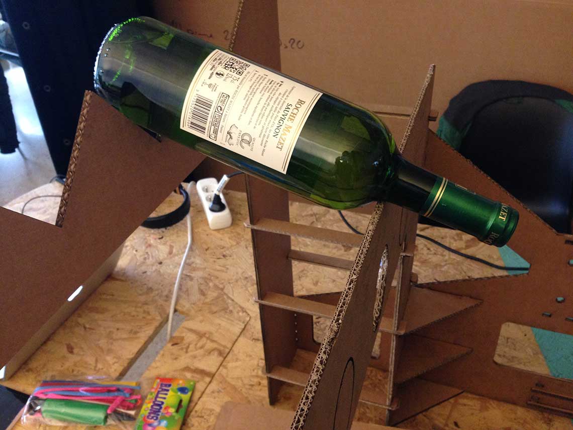
 And here is a little video of the assembly step !
And a video showing how the machine will operate :
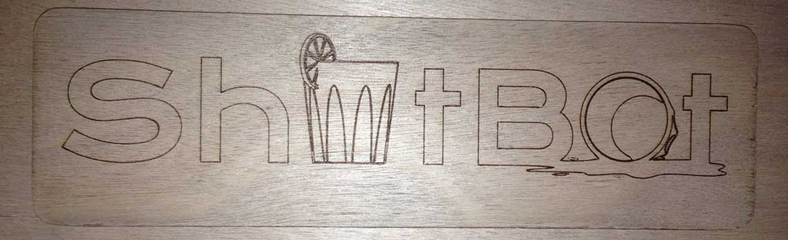
I also worked along with Ludovic on the creation of a logo for our machine that we decided to call the
My work stops there for this week. See Machine Design week or the Group Page for the next steps...