GROUP PROJECT : MAKE A MACHINE
Software and equipment used during this week
- Laser cutter for the structure
- CNC mill for the FabNet
- 3D printer for the tap system
- One Arduino board and One raspberry Pi to control the "l axis"
- Material :
- 5mm cardboard and 5mm plywood
- PLA
- Software :
- Rhino for the design of the machine and the 3D parts
- Cura for the 3D printed parts
- Atom for programming
- Arduino IDE for arduino sketches
- Other equipment :
- Silicon tubes
- Plastic taps (for acquarium aeration systems)
- Plastic connectors (for acquarium aeration systems)
Watch the presentation video
The team
- Frédéric Jaffres- Guillaume Attal
- Ludovic Foreau
- Roman Kutyin
- Thomas Feminier
- Vincent Guimas
Introduction
These two next weeks will be all about teamwork ! The goal is to imagine, design, fabricate and operate a machine, using the kit that will be provided to us. This group project is a perfect occasion to put in common all the techniques and principles we've been learning so for during the Fab Academy. The project will be devided in two parts : the mechanical design (design, structure, mechanism) and the machine design (the program, the interface, etc.).Part 1 : Mechanical design
The assignment
Make a machine, including the end effector,build the passive parts and operate it manually,
document the group project and your individual contribution.
The idea
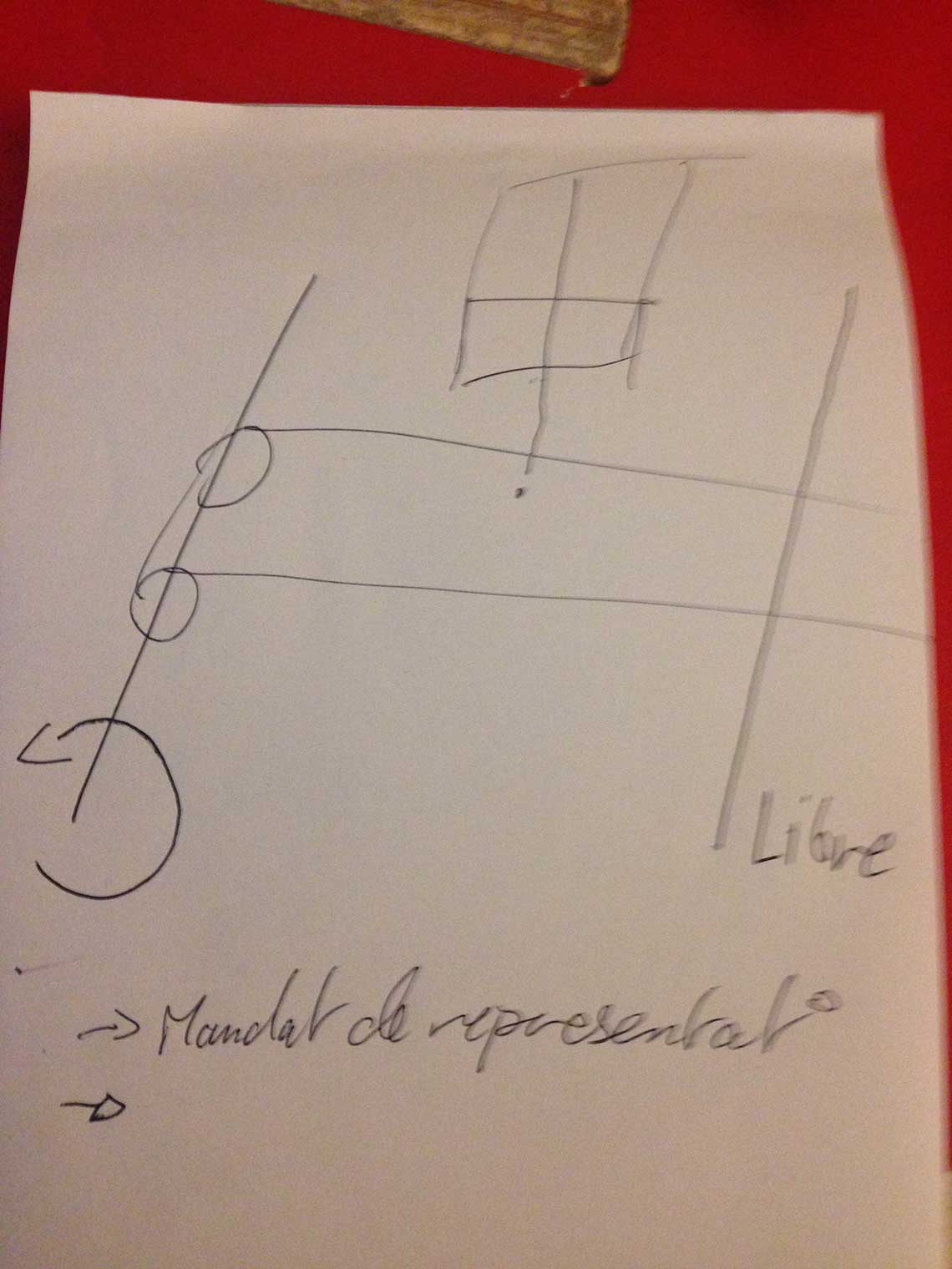
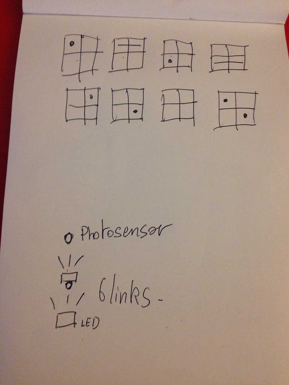
First thing we had to do as a group was of course to all agree on an idea for the machine. We decided to individually think of one idea and then to share them and decide which one would be selected. So here is an overview of the sketches that where proposed by the group :Guillaume's electronic music maker :
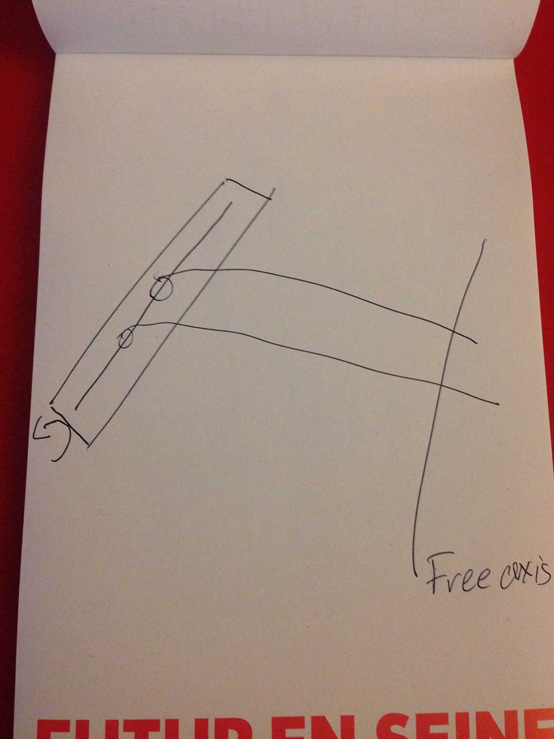
Thomas' drawing machine :
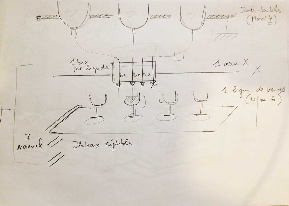
Ludovic's cocktail maker :
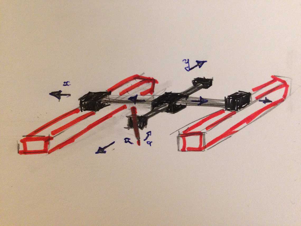
Roman's version of the cocktail maker :
 In Roman's version, the bottles are positionned with the head down and the idea is to use servo-motors to open and close the circulation of the fluids in the hoses.
Frederic's version of the cocktail maker :
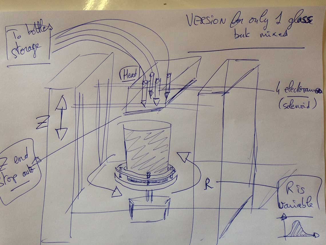 Frederic proposed a version where there would be only on glass placed on a rotative bed. A variable rotation would be applied to act as a shaker.
And so without any surprise and after a very short concertation, the winner is : The Cocktail Maker.
It will be a machine that prepares shooters, just like your favourite barman does !
 We will still have to find a proper name for it, but it will come later.
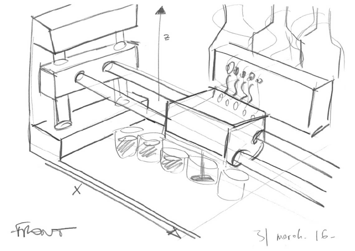
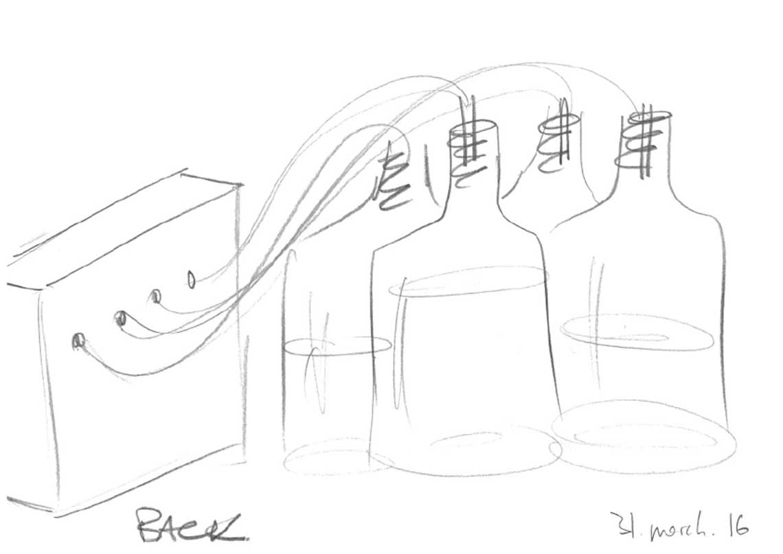
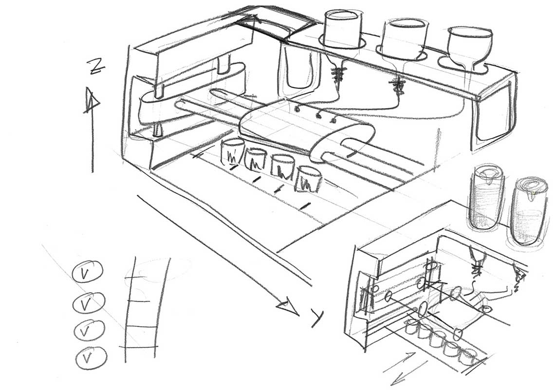
Here is the final sketch that we did together to agree on the general structure and mechanism :
Main notes about the machine :
- The machine serves shooters, mixing different beverages directly into shot glasses
- Each bottle is connected to the head (lets say there are 4 of them) and has its own extruder
- The bottle will be disposed with the head down like in Roman's design and we will use solenoid valves for the distribution of liquids
- For the moment we will only use one axis, X, to move the nozzle horizontaly (and we will add an other one later I we have time)
- The glasses we be disposed in one raw (or several raws if we decide to use a Y axis)
- The glasses will be placed on a removable bed standing on a multi-level rack. This way we will be able to manually modify the Z. Also, the bed can act directly as a tray for serving the shooters.
Work Organization
Now that we agreed on the idea, we had to work on the design of the machine. To do that, it was important to decide what would be the task of each team member for the whole project (not only the 1st part). We noted 6 different tasks to do :1. Make the model of the machine
2. Build the prototype
3. Design the electropnics
4. Write the code
5. Create the interface
6. Document the project for the group
Each of these topics will be subdived in different tasks that we have to determine. For this, we will be setting up a Trello board to organize our work efficiently. According to the skills and expertise of each member of the team, we will then be able to complete this table :
| Student | Task |
|---|---|
| Frédéric | Fluid mechanics, development |
| Guillaume | Prototyping and Development |
| Ludovic | 3D model of the machine |
| Roman | Development, electronics |
| Thomas | Documentation, 3D model of the machine |
| Vincent | Documentation, prototyping |
The design
Structure
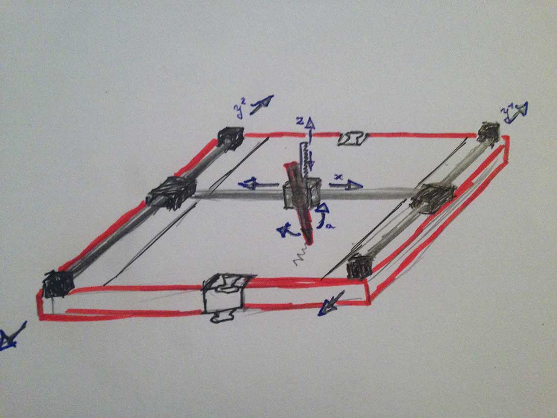
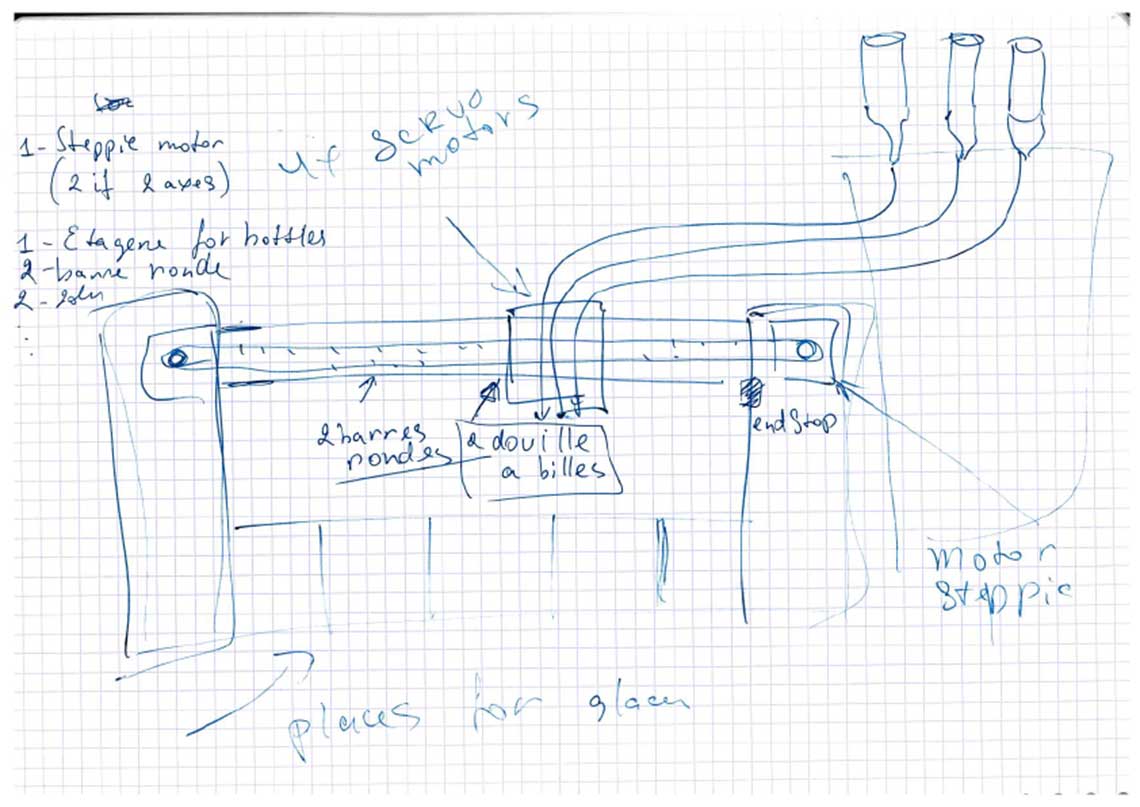
The design and modelling phase being essential, we spent quite some time on it. First, of course we tried to determine as precisely as we could what should be the structure of the machine. So we exchanged a few other sketches :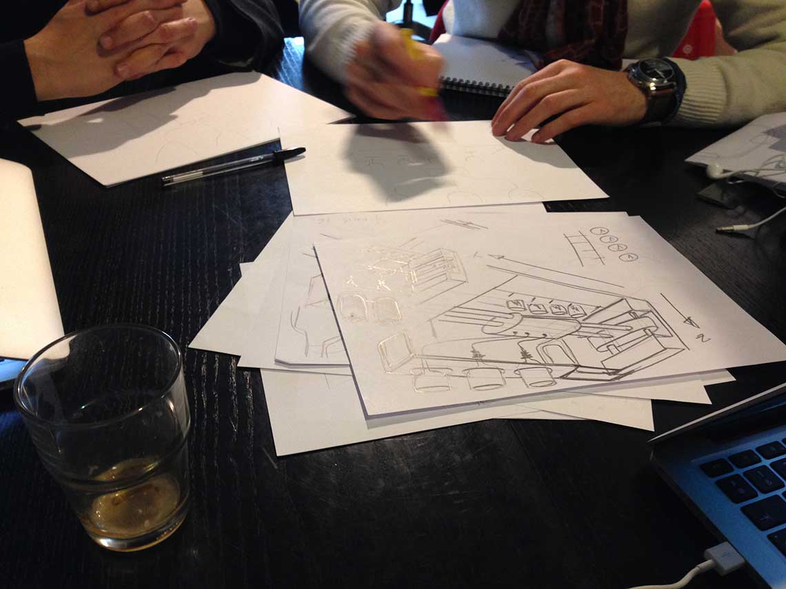
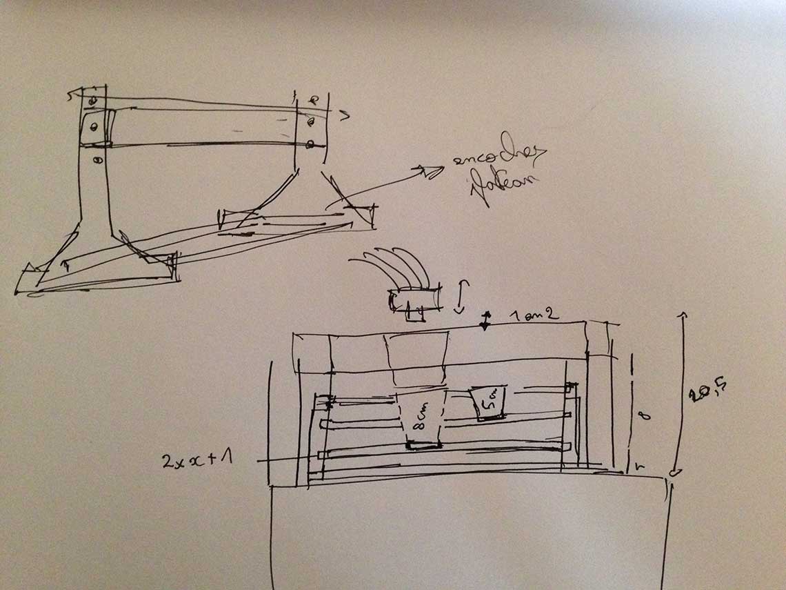 We decided that the best thing to do would be to lay the bottles at 45° on a stand, at the back of the machine. This was the first determinant choice.
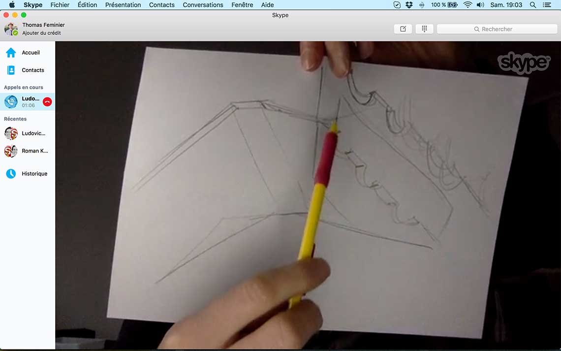 We also took the time to measure each element included in the kit that we have received, which was essentiel to design a suitable structure.
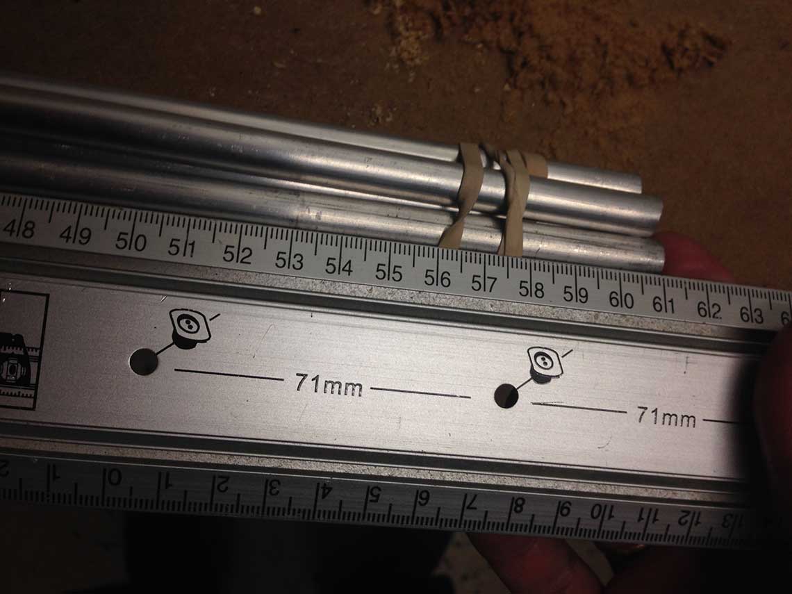 It was especially important because we realized that the shafts were by 10cm larger than they were in the model file provided for the assignement. So we would also have to redising the whole wrapping structure for the motor and the nozzle.
We began with this part because the motor and the shafts were the elements that would determine the dimensions of the whole structure :
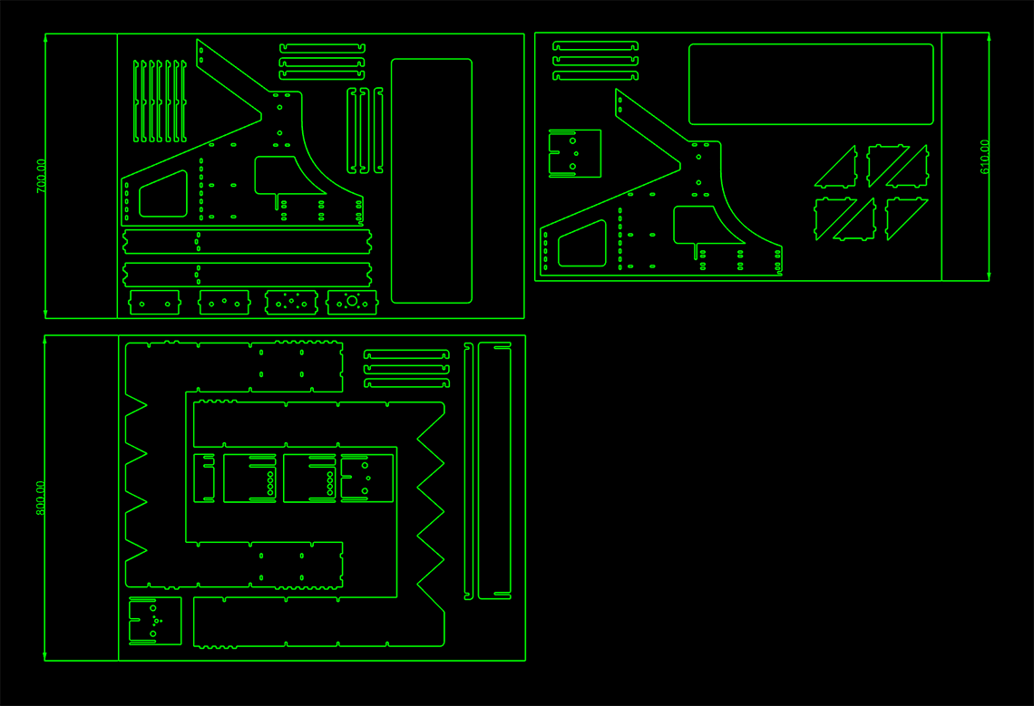
 Then we where able to build the structure, making it as stable as possible. Note that we chose to begin by designing a 3D model first, to have a good overview, and we picked a 5mm thickness because we wanted to work with cardboard, plywood or MDF that we would laser cut, rather than using the CNC mill which not available very often at the lab these days.
Once the main structure was made, we could continue with the bottle stand...
Then we where able to build the structure, making it as stable as possible. Note that we chose to begin by designing a 3D model first, to have a good overview, and we picked a 5mm thickness because we wanted to work with cardboard, plywood or MDF that we would laser cut, rather than using the CNC mill which not available very often at the lab these days.
Once the main structure was made, we could continue with the bottle stand...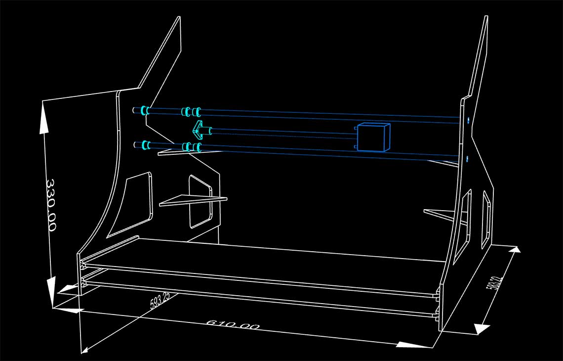 The best way to do it was for us to model the bottles from measures we took on real liquor bottles :
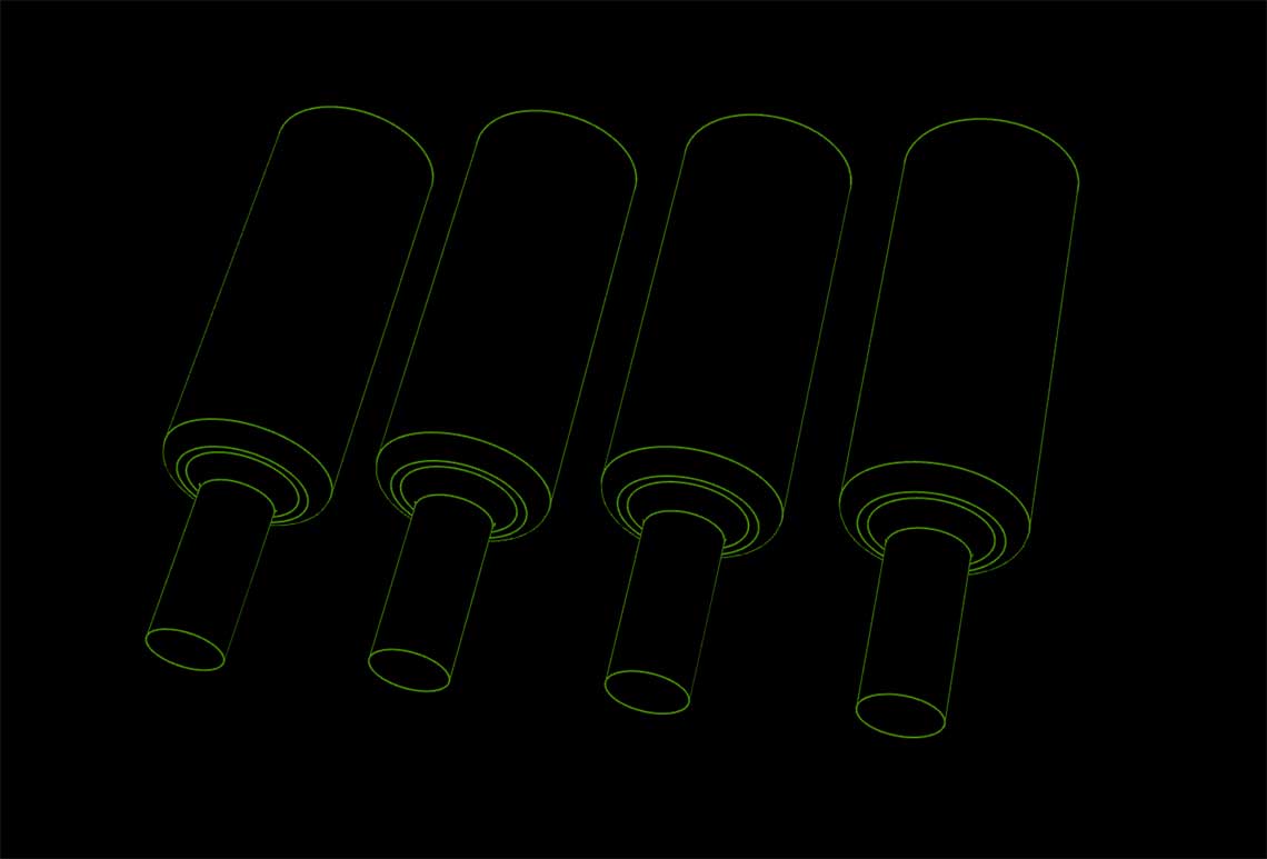 From this it was easy to design a stand for the bottles, attached to the main structure for more stability :
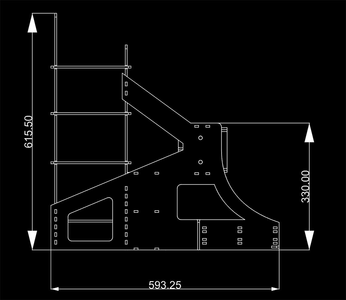
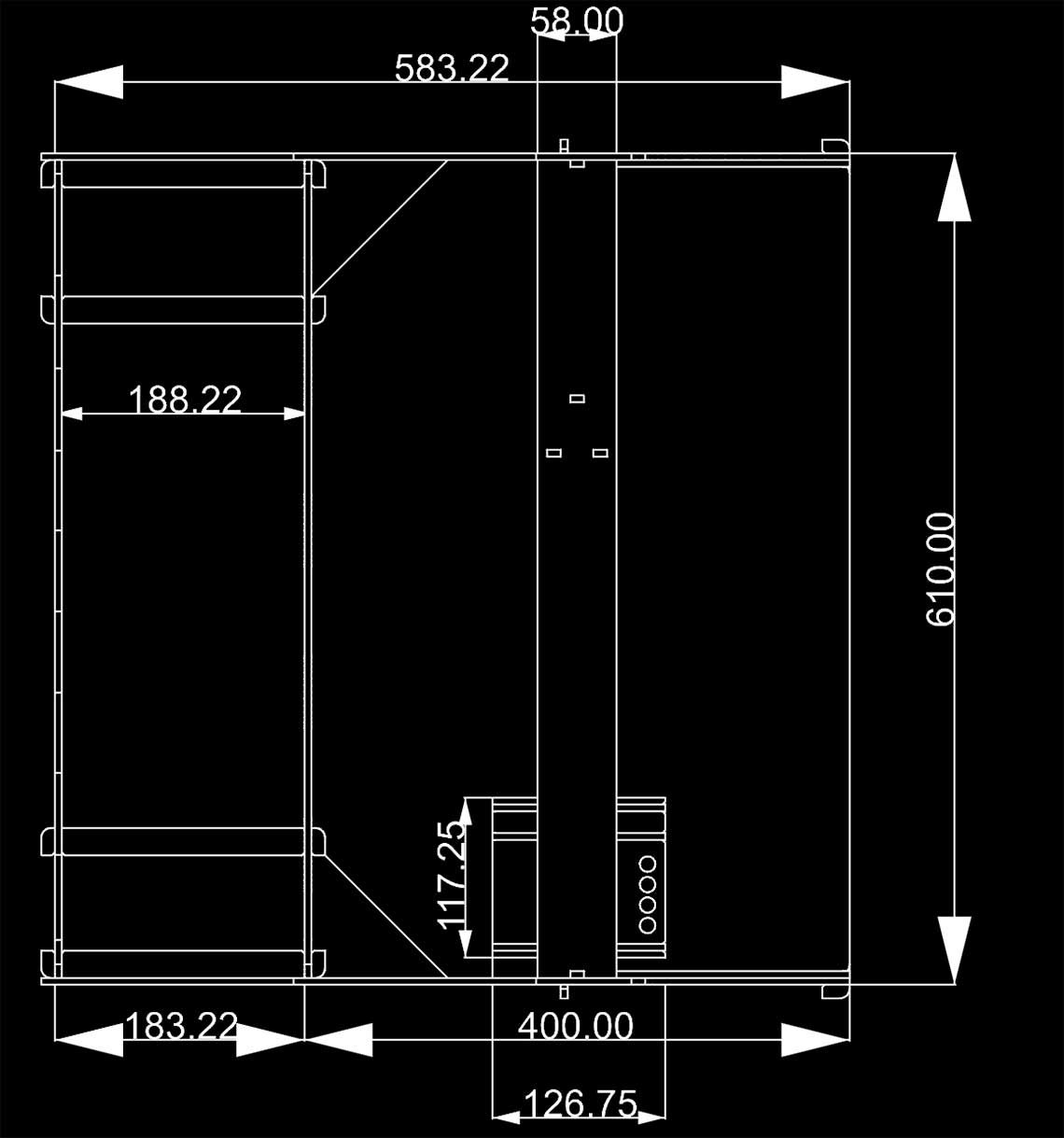
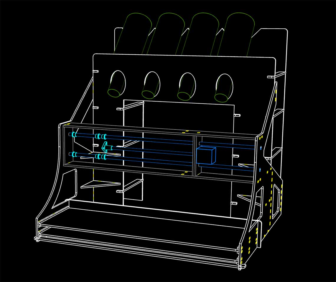 Here are some 2D views with the dimensions :
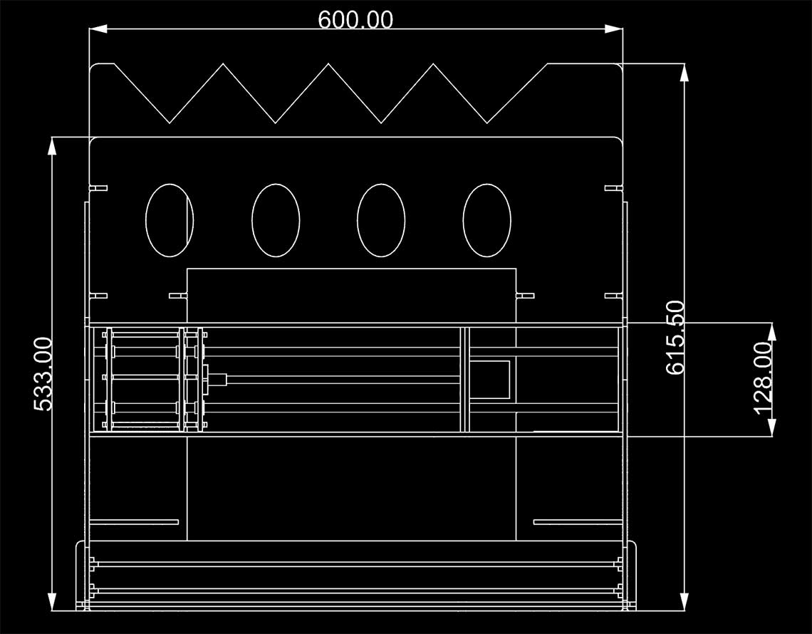
 After the first assembly we noticed we had to make some changes in the design. Here we decided to add to "bridges" (in yellow) to reinforce the front of the structure : On bellow the trays, and one behind them.
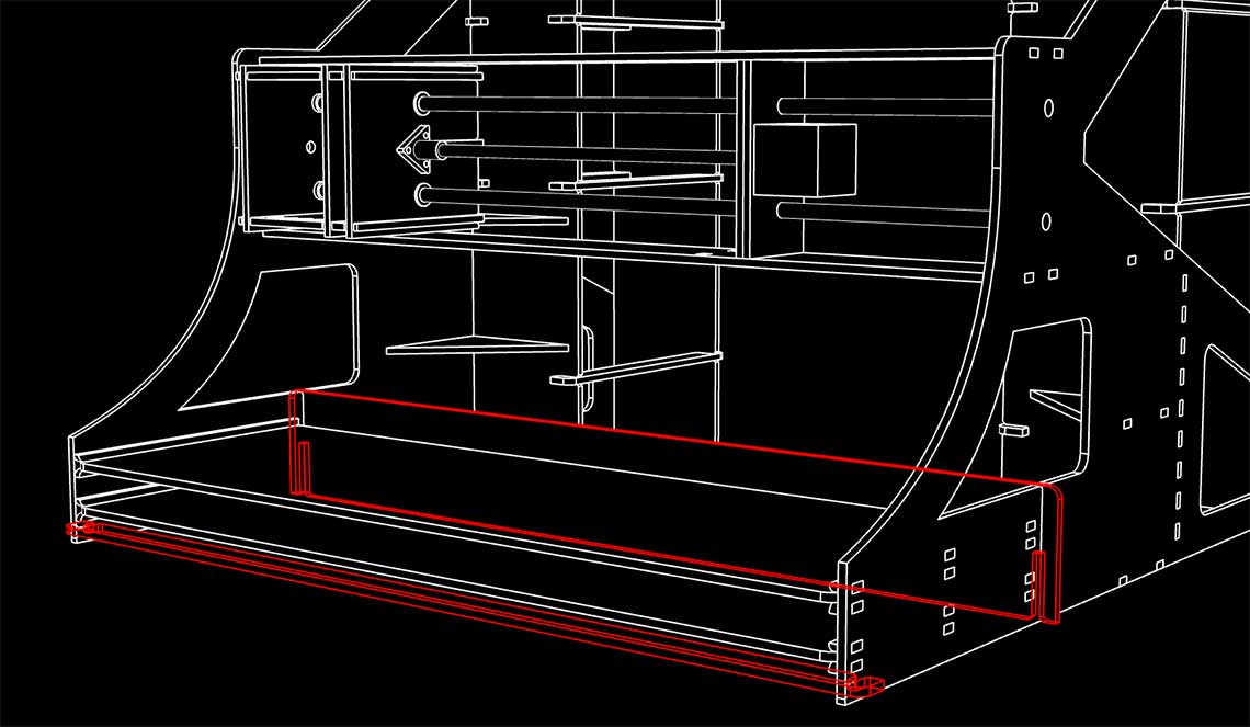 Finally we re-designed the bottle stand because we did a rapid test with a whine bottle and realised the front holes where too large and too low :
 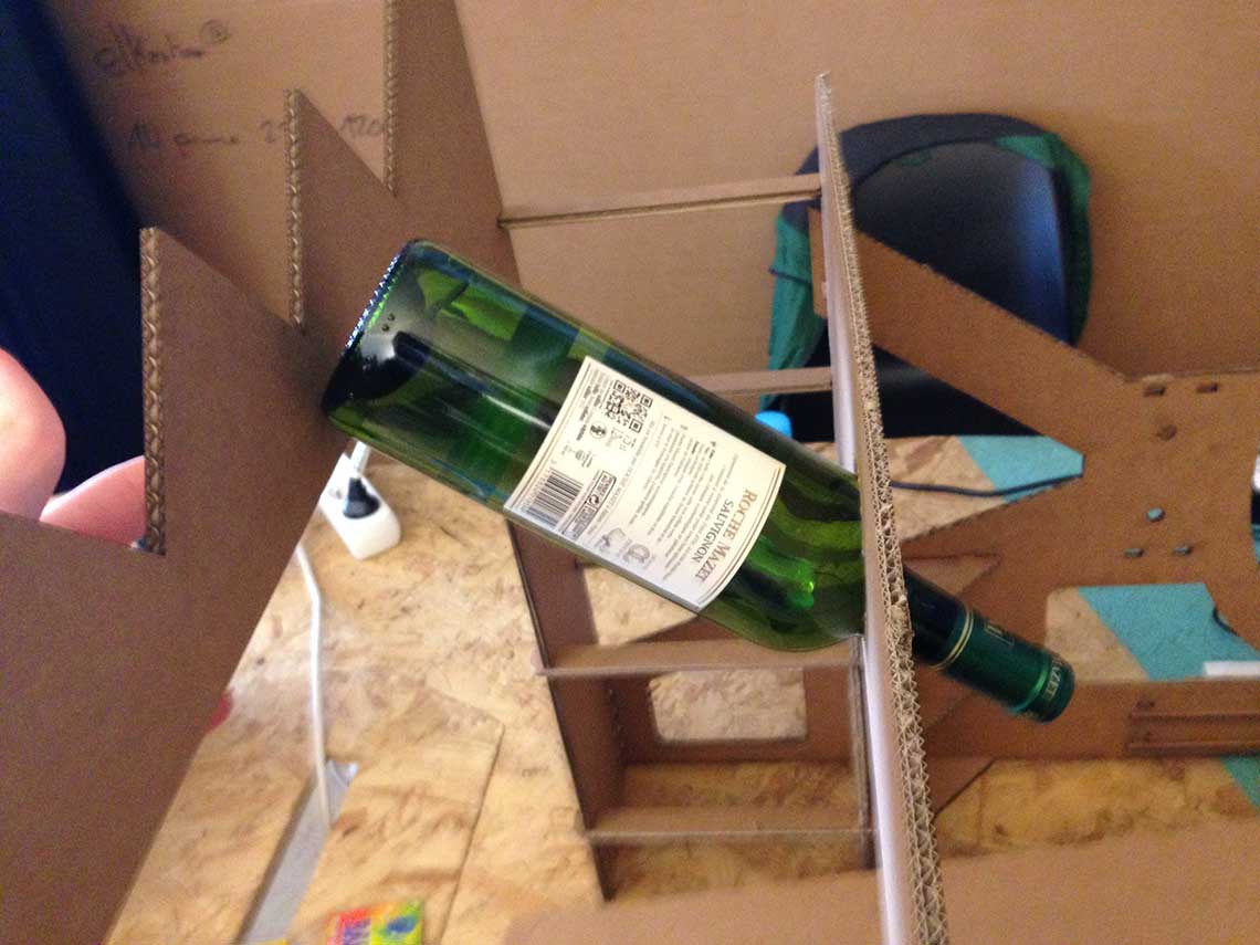 So instead of holes, we reproduced the same triangular shape on the front part of the stand, like this (did it directly on the cut paths) :
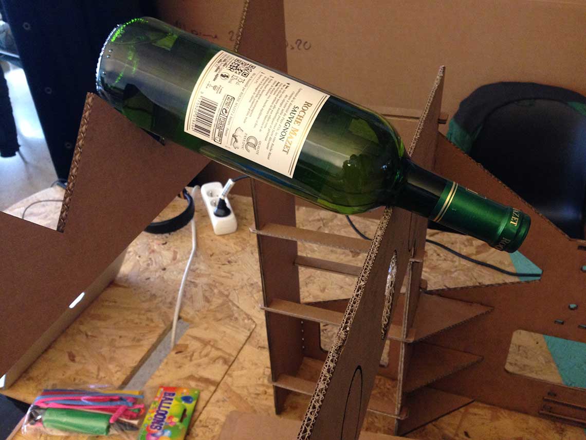
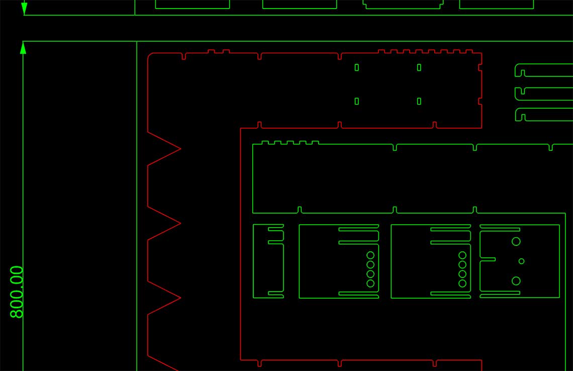
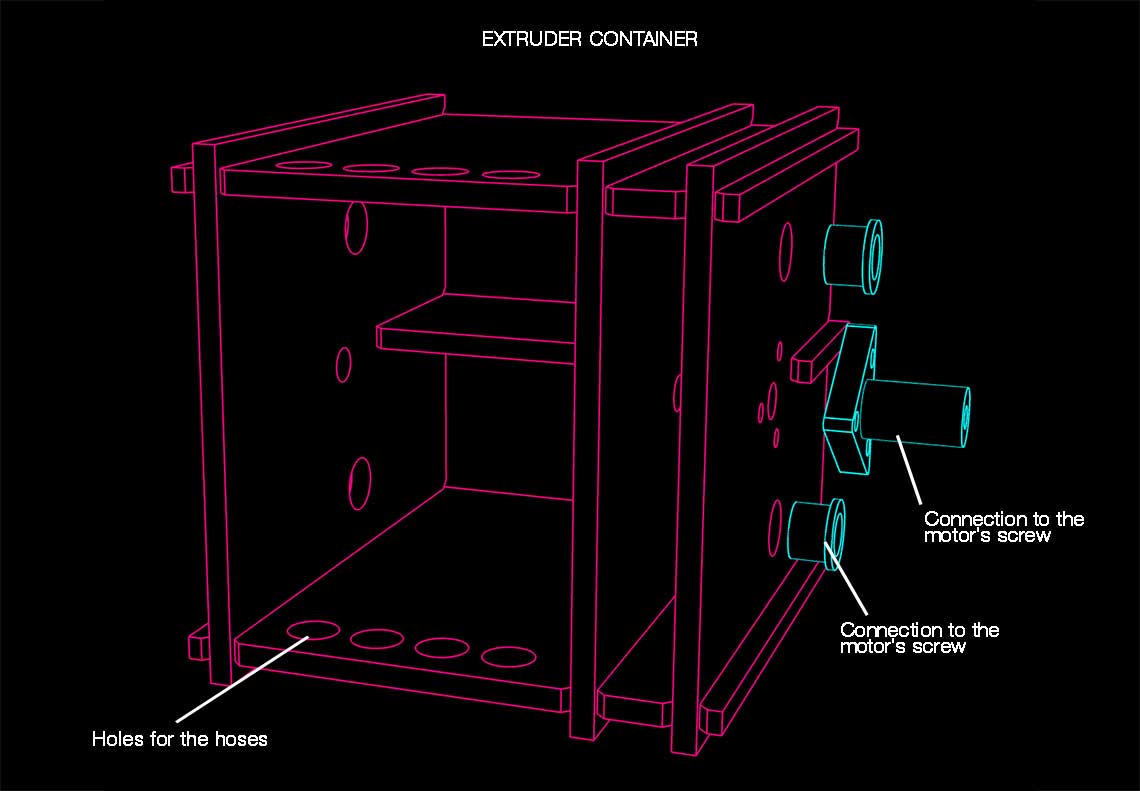 The 4 holes on the top and bottom parts are the holes through which the hoses connected to the bottles will pass.
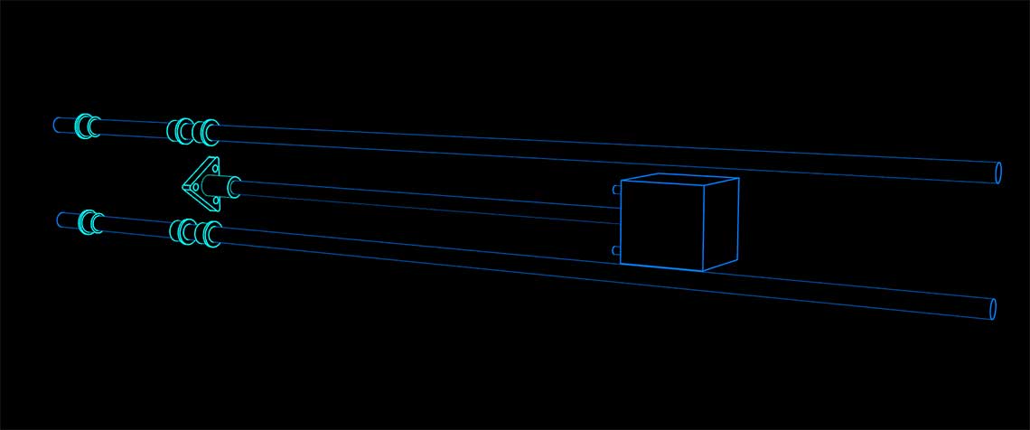
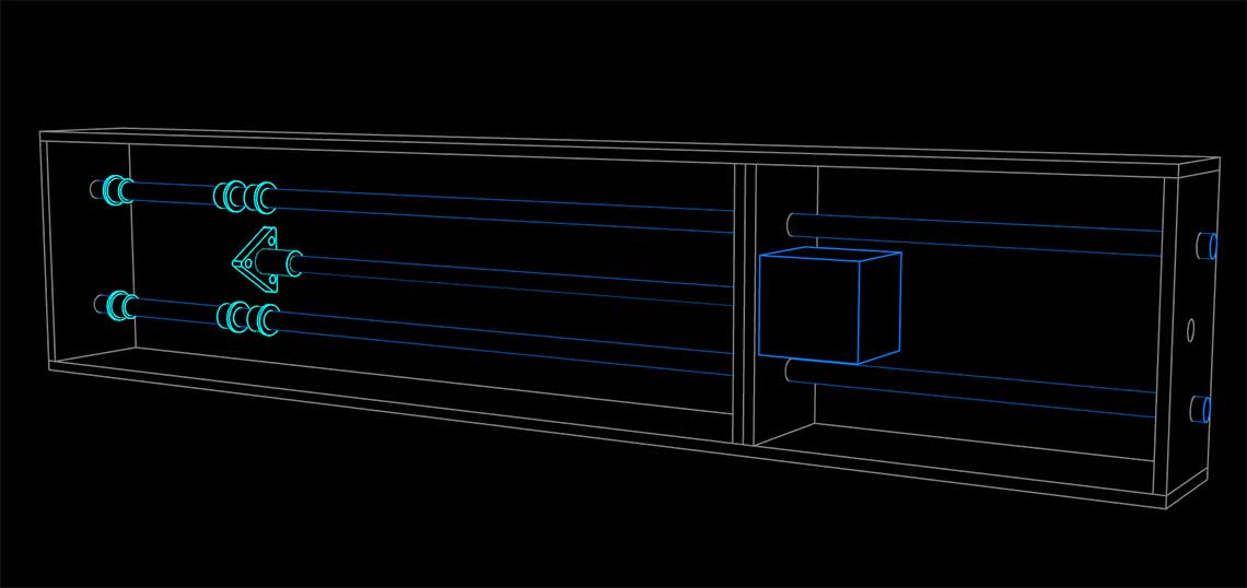
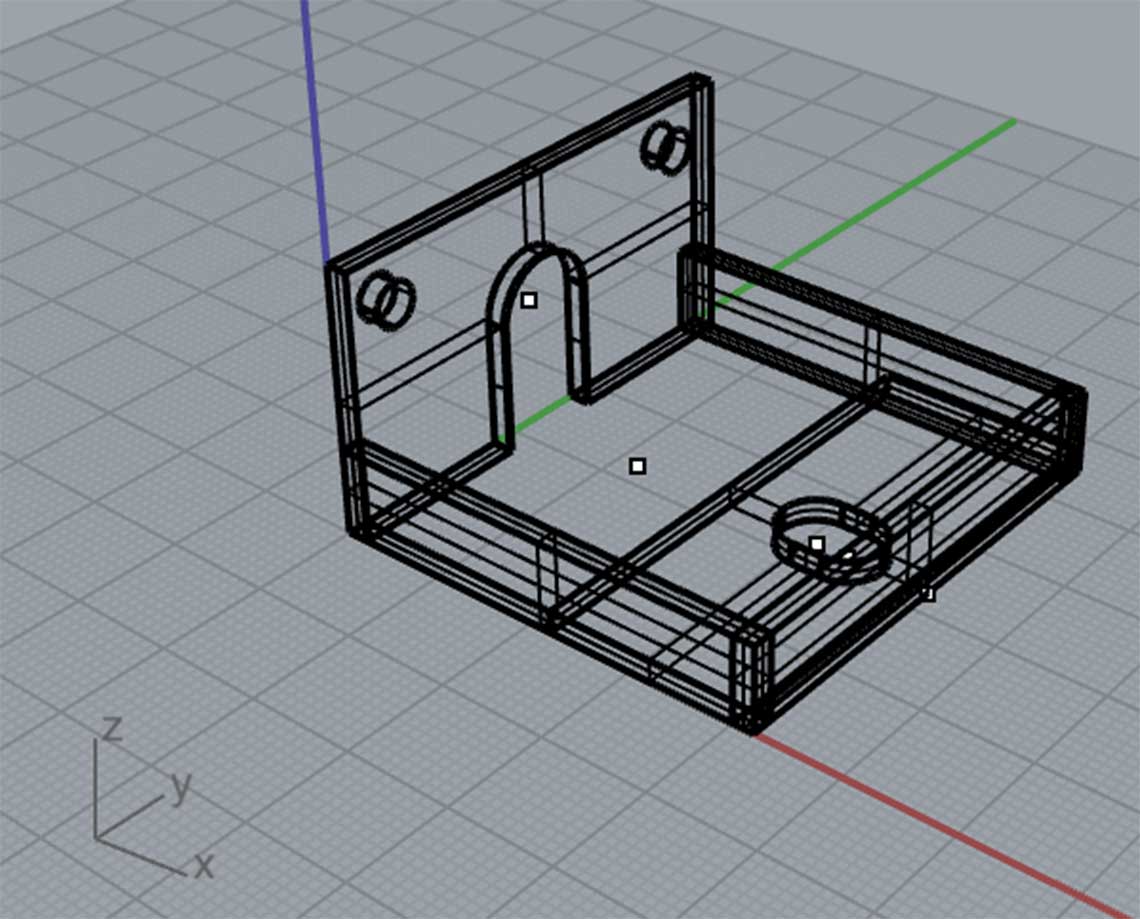
We then designed a part that would be printed in 3D and that would be placed on the bottom of the moving box and will act as a quadruple nozzle :
The 4 holes on the top and bottom parts are the holes through which the hoses connected to the bottles will pass.
We then designed a part that would be printed in 3D and that would be placed on the bottom of the moving box and will act as a quadruple nozzle :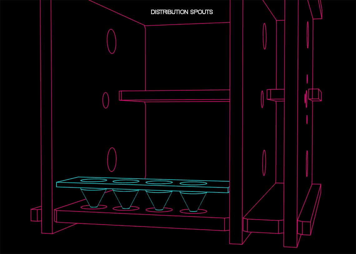 Here is a larger view with this nozzle mounted on the rails and motor :
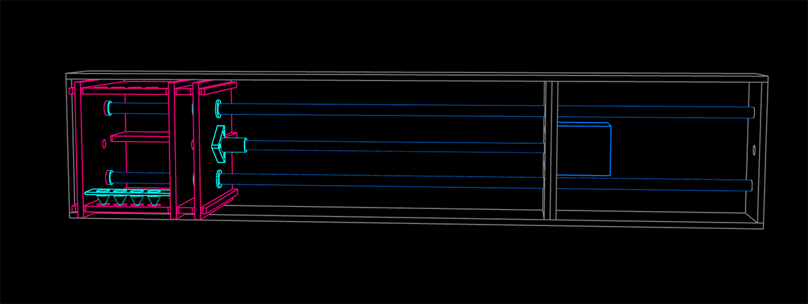
Liquid distribution system
In parallel to the work on the structure's design, we were also working on the system that we would use for the distribution of the beverages. This was the only part that was not yet decided when we began the design... We though of several different solutions. One of them was to use what is called a "peristaltic pump". We found a example of this system, along with ready-to-print 3D models on Thingiverse. This system uses 4 Nema 17 steppers. The advantage is that this way we would not need to put the bottles with the head down because it works as a pump. The problem was that we did not have such motors and that there was a certain cost to acquire them. We also thought that we could design a valve system that could be printed, and used with servo-motors to turn the stream of liquid on or off. Here is the 3D model of the tap :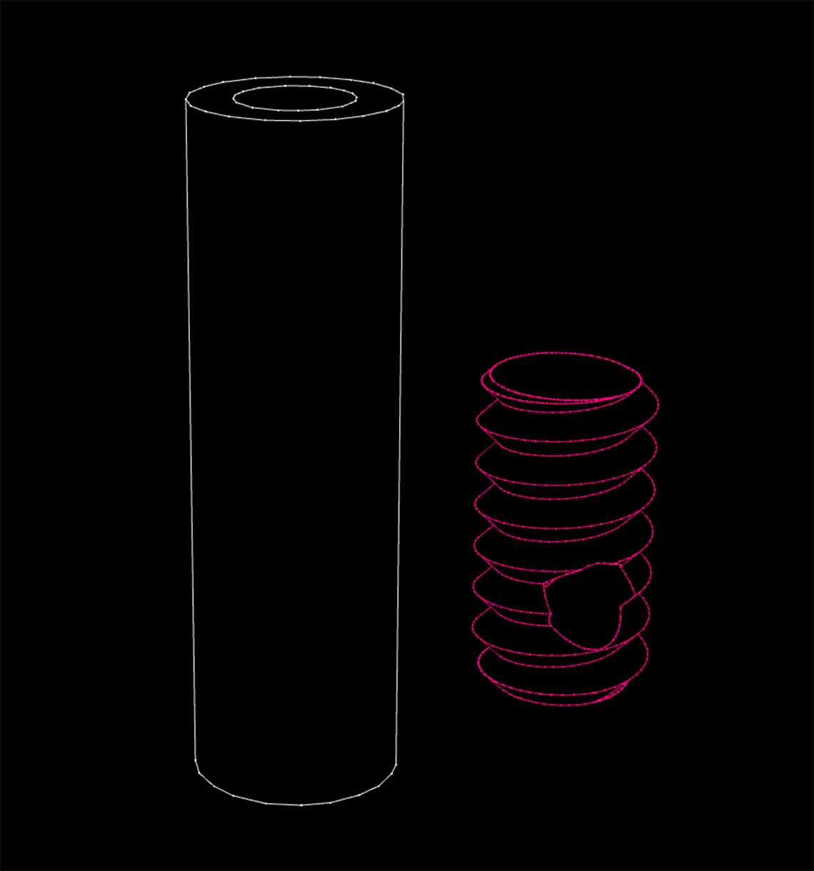 And here is the the whole system, including connections with the servo-motor :
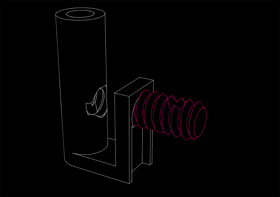 The idea is to connect this tap to a servo-motor directly to the neck of the bottle using a spout like this :
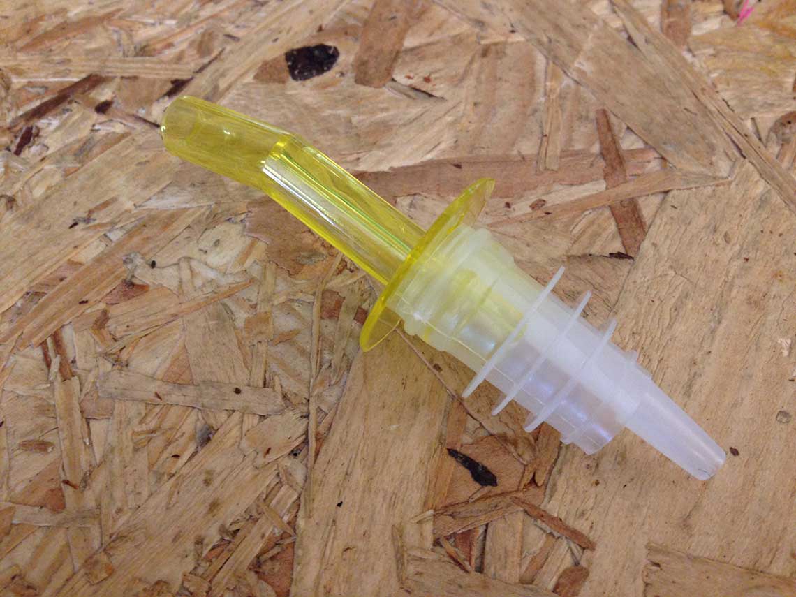
Prototyping
Structure
Then we laser cut the parts. Unfortunately the laser cutter at Woma was not available due to maintenance so we had to go to Vincent's Lab. But it turns out that their laser cutter was acting quite strange so we spent a lot of time trying to get the right configuration and did not really succeed. It turned out that the bad was not completely flat and also that the lens seemed quite unfocused so the cut was not clean and the cardboard was burned in some parts.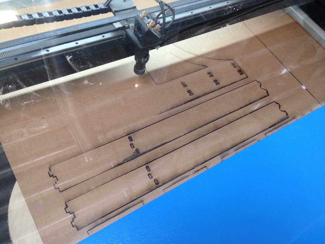 We managed to get all the parts cut anyway but we had to do a lot of hand cut (using a cutting knife). Then we assembled the parts together and voilà ! :
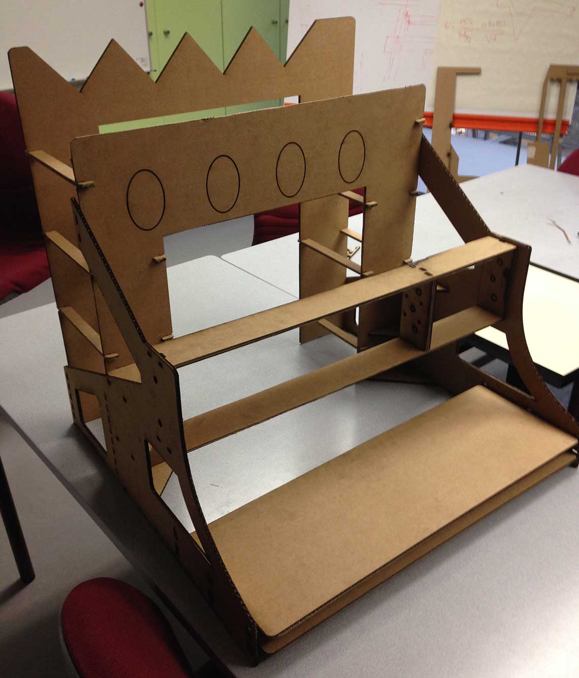 Generally the structure was OK and pretty stable but we decided the next version would have to be made of a stronger material such as plywood. We also noticed a few things that could be improved. Here the connecting teeth were missing in the cut file:
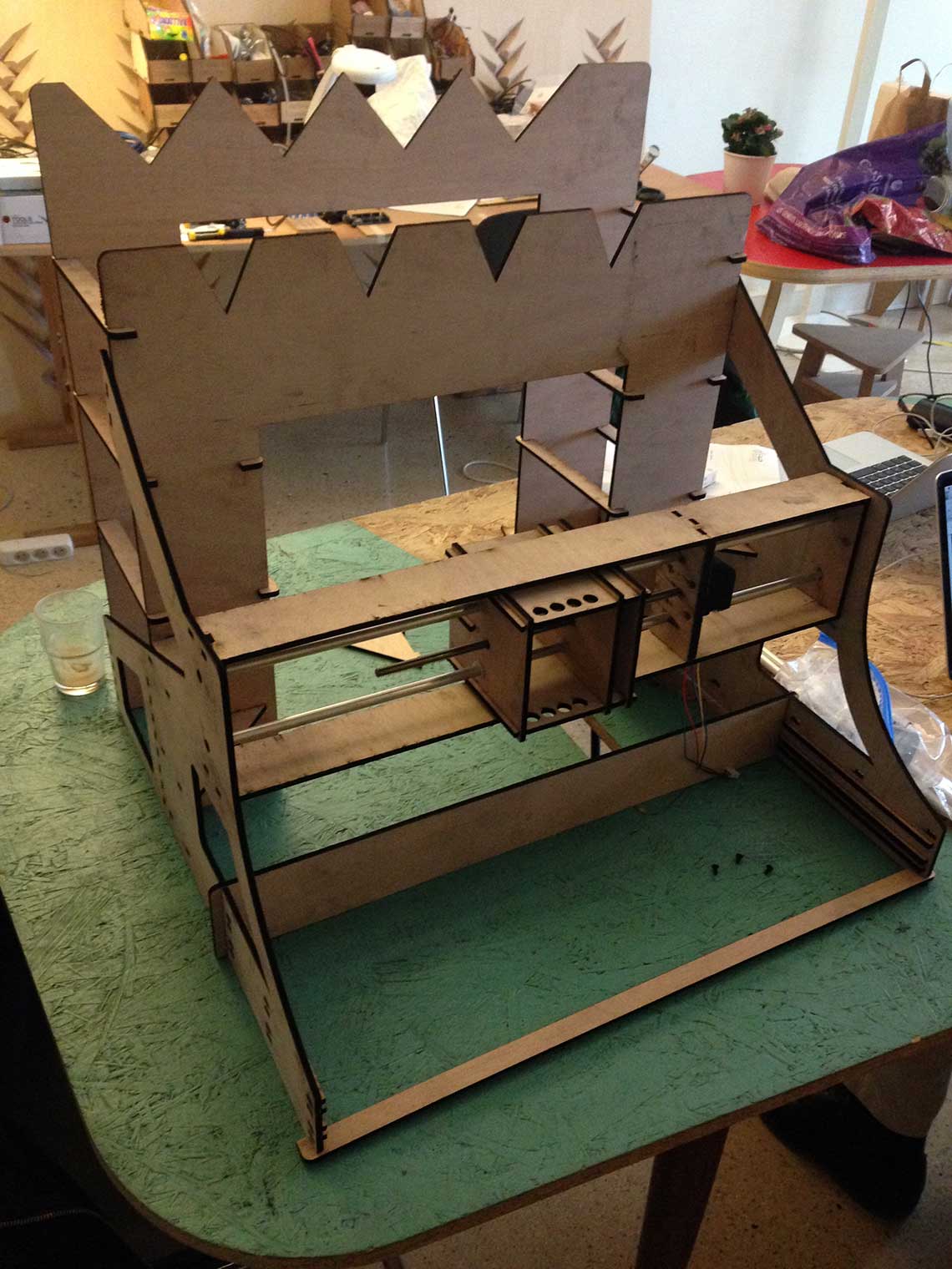
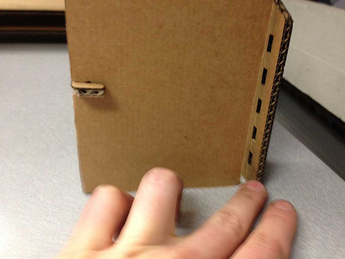 Once the design had been remade, we could cut a new version, this time with plywood. There would be some improvements to be made regarding the settings of the cut because the wood is really burned and leave a lot of stains, but it will do :
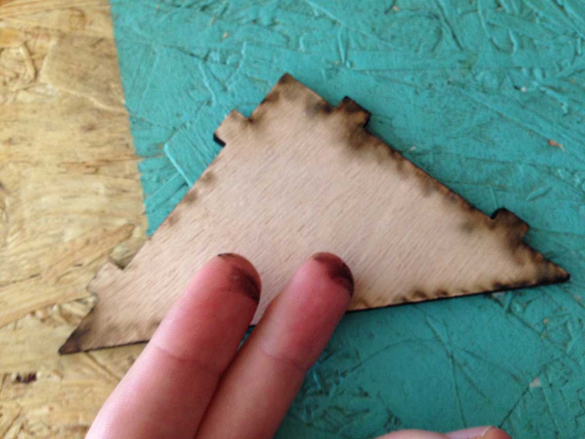 And here is a little video of the assembly step !
And a video showing how the machine will operate :
And a picture for more details :
Liquid distribution system
For the liquid distribution, our fisrt idea is to apply the principle of communicating vessels.Here is a test of a 3D printed tap system (perforated screw + tube). This is actually the 3rd test, the two previous ones were not working because the screw was too large :
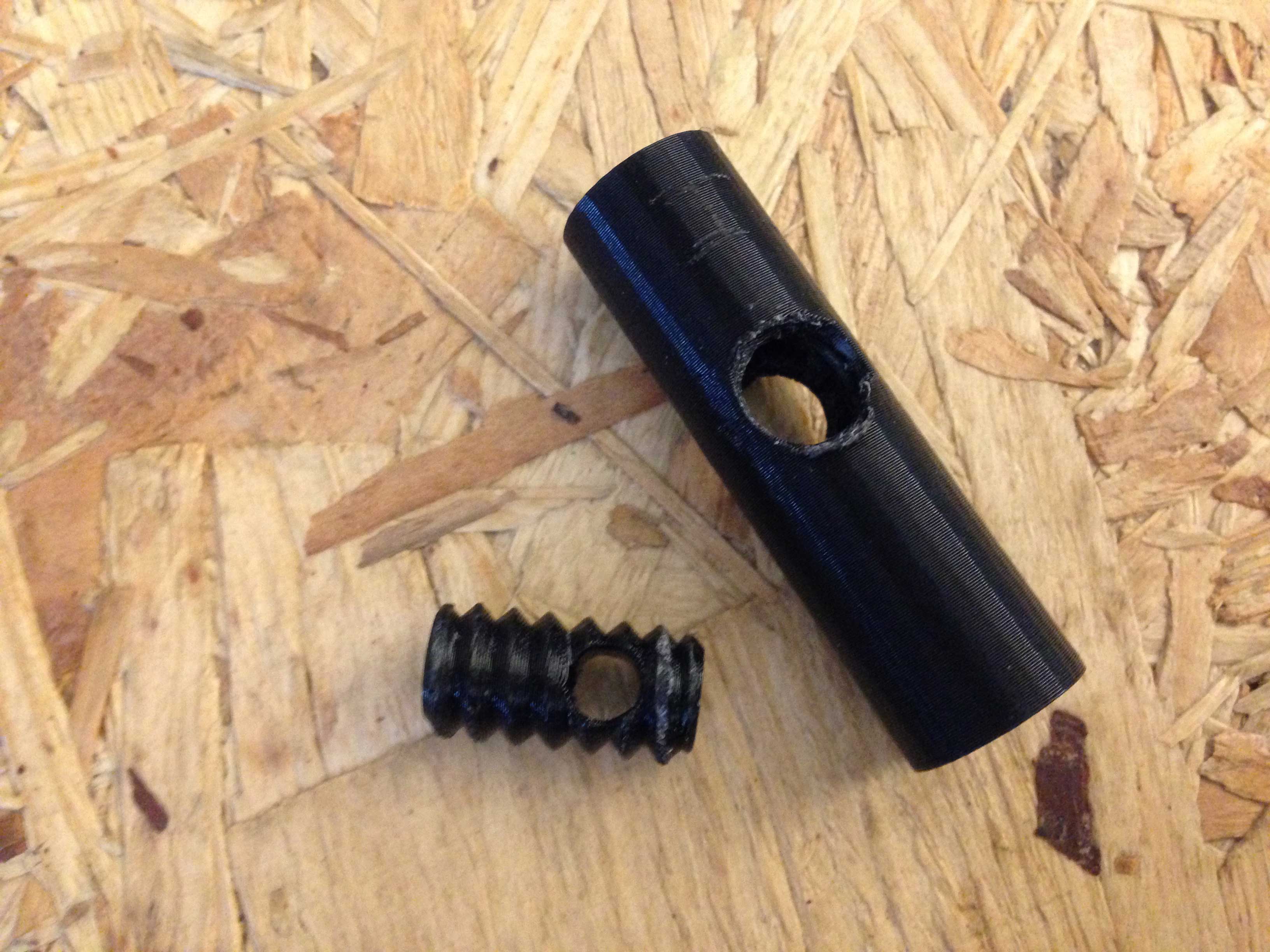 Then we also printed the second version :
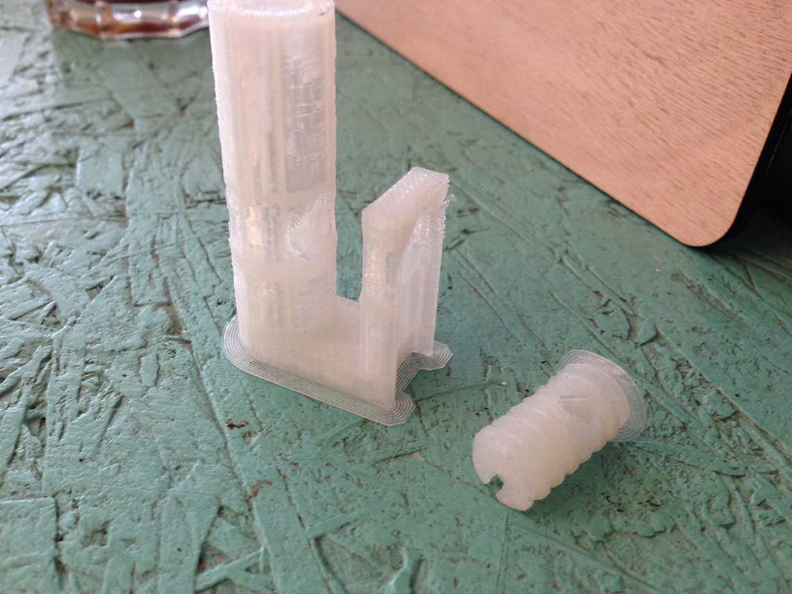 And the quadruple spout :
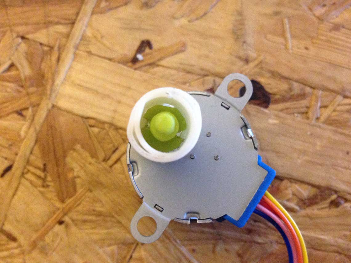
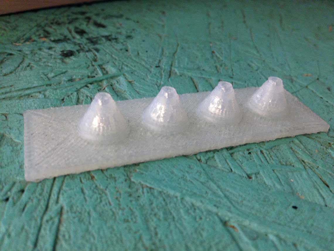 After some more tests, we realised that this solution would be to complicated. So we decided to use existing taps rather than trying to make ones. We found those tiny taps made for aeration in fish tanks, that go along with silicon tubes :
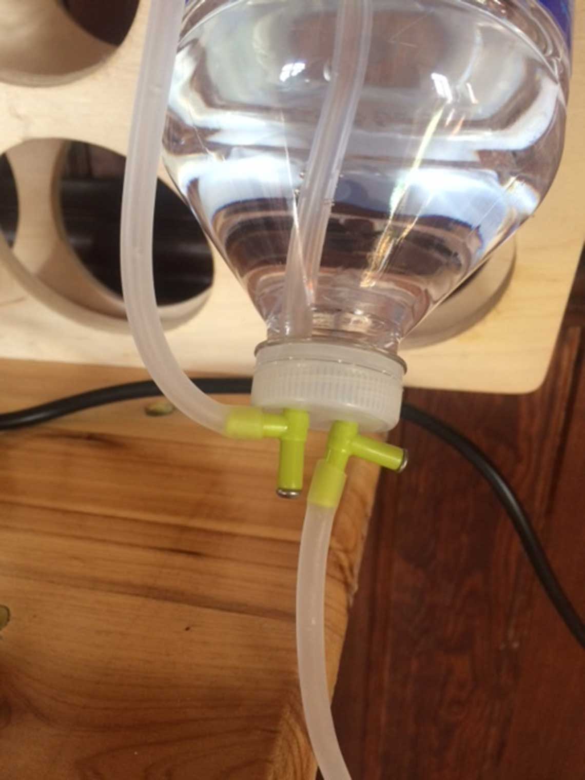
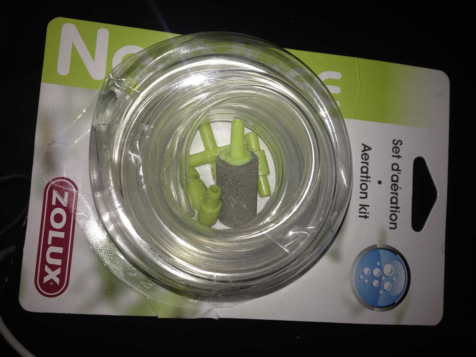 And those are the tap and the connector for the tubes :
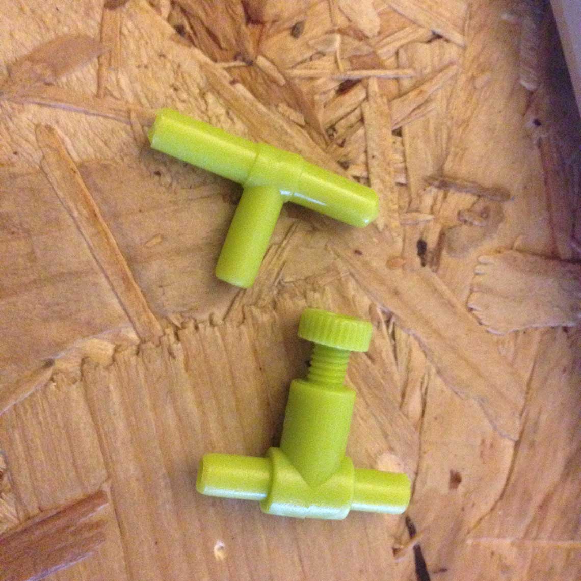 This kit only costs 6 euros so it is a really cheap option !
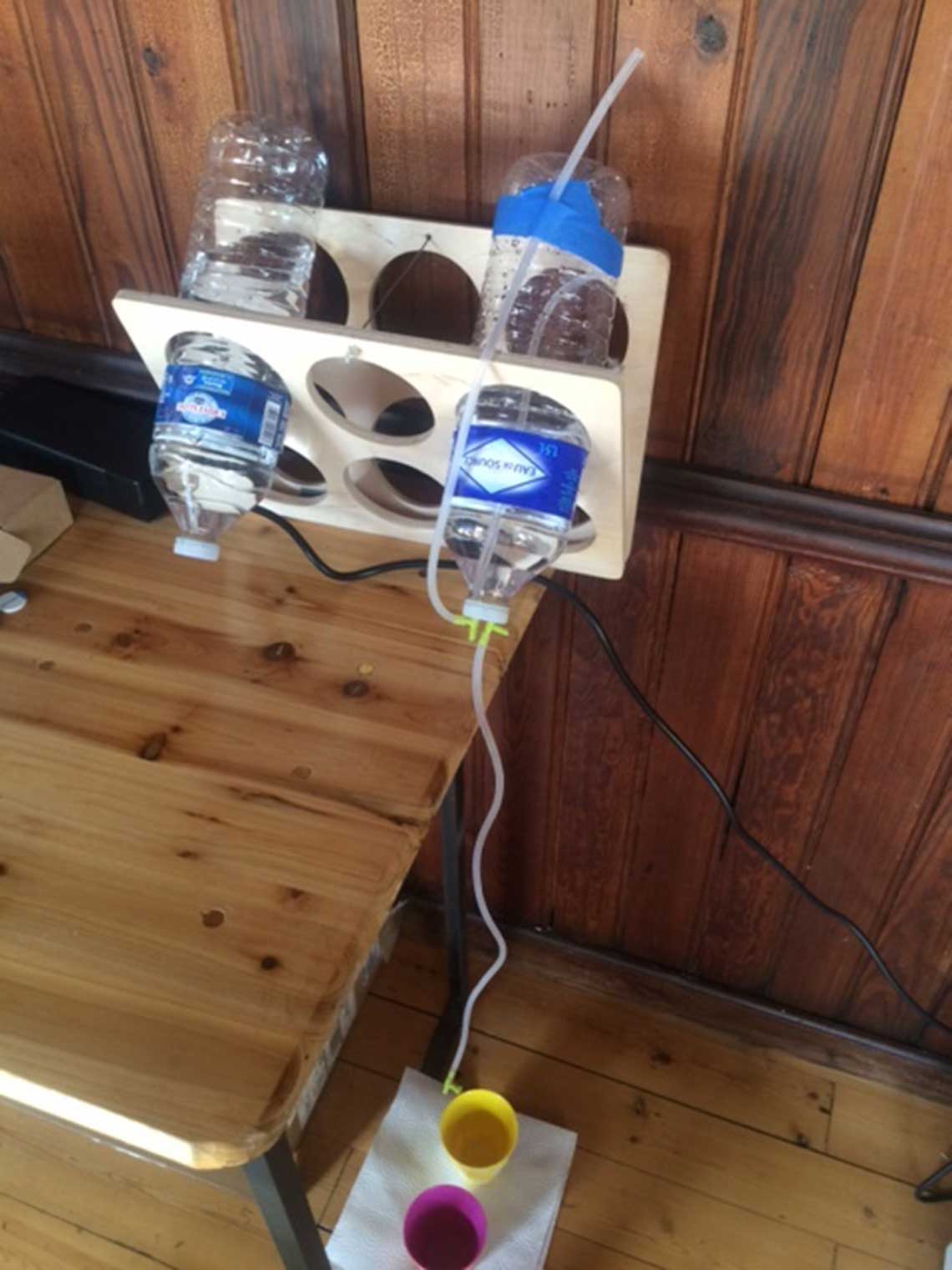
With this system we did a little simulation with a bottle of water. We use a first connector to link the tube that goes out of the bottle and down to the tap, and a second one linked to another tube that goes up to act as an air supply duct :
The idea is to connect directly a servo-motor to screw of the taps to open and close them. For a tap to be open, we must apply a 900° rotation to the screw. So in order to do that we would have to modify the servo-motor to suppress its rotation limit. We found this tutorial on instructables to do this and we wanted to try :
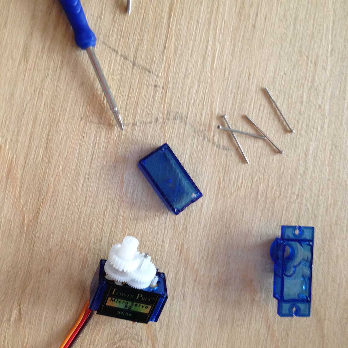
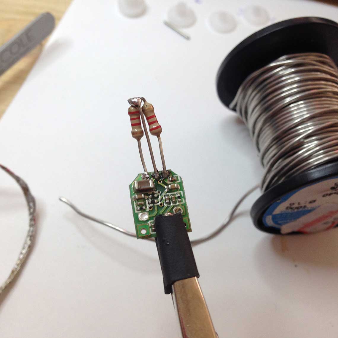
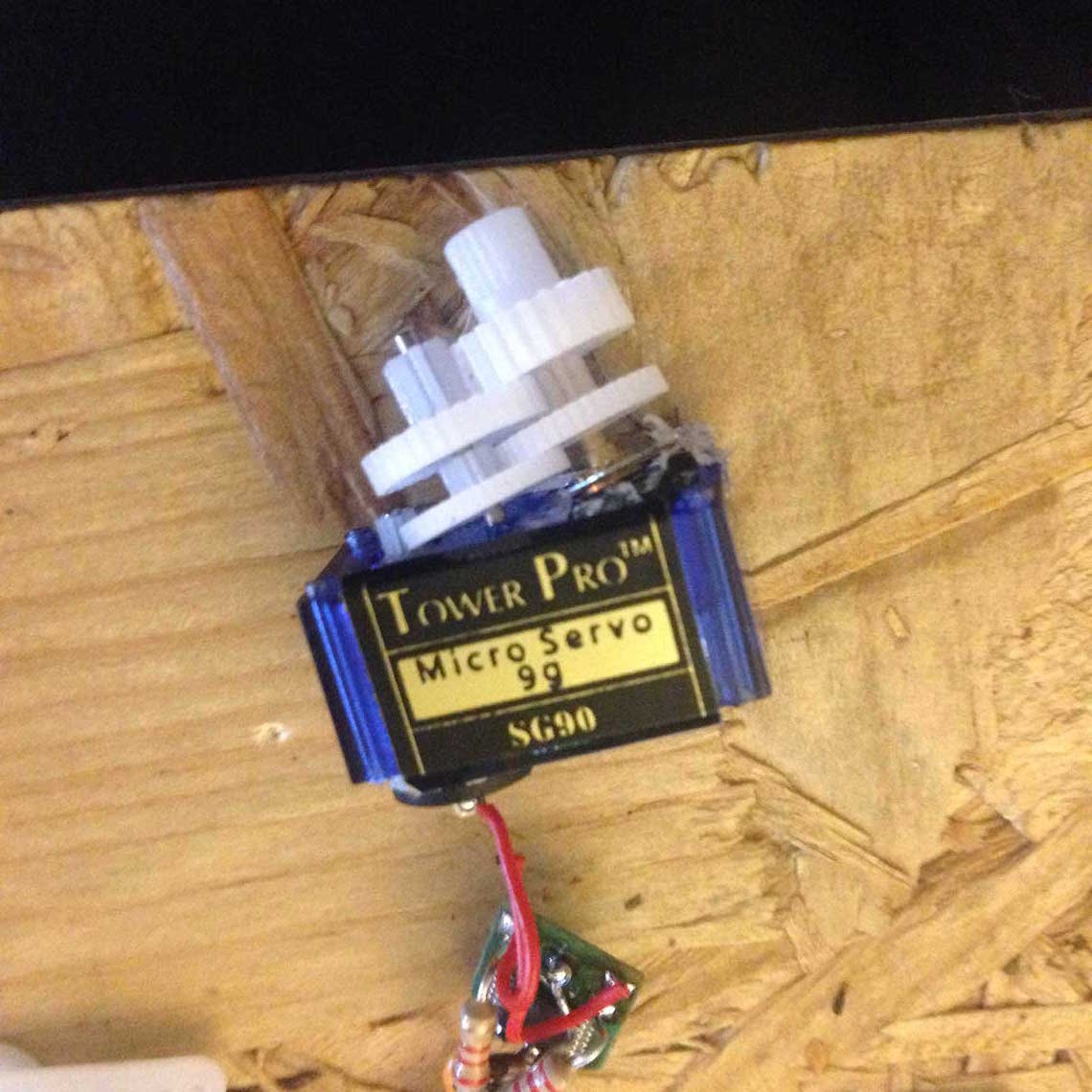
We had no more servo to destroy at the lab, so we decided we would continue with a stepper motor instead.
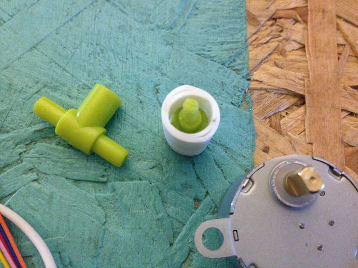
To connect the servo to the tap, we designed this piece which is an adaptator : on one side we connect the servo, and on the other side we connect the head of the tap's screw.
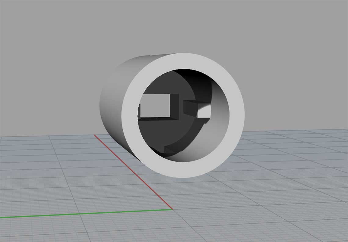 Then we printed the part. It just needed a little incision on both sides of the screw's colar to fit it into the adaptator :
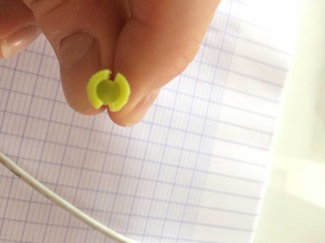
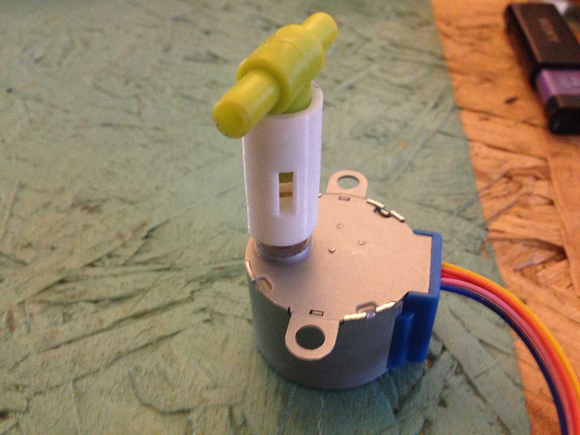
 And this is the printed part :
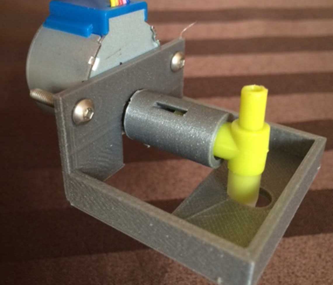 Settings used in Cura for the printed parts :
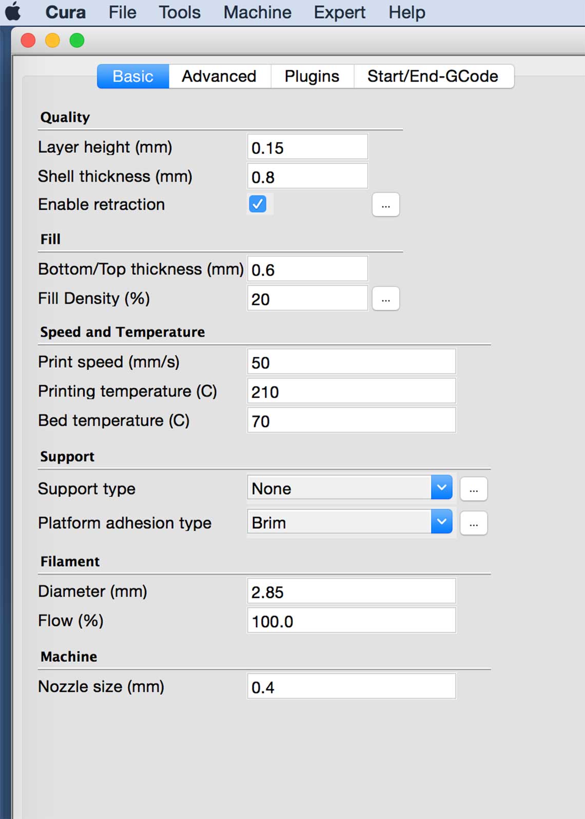 An other solution has been studied to backup if needed the first solution explained here above. This backup solution is based on peristatic pumps.
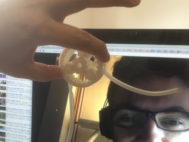
The concept of a peristaltic pump is to pinch a tube containing liquid between an outside wheel and inside wheel. By pinching the tube, the liquid is up with control. The peristaltic pumps are used in the medical industry to manage the flow of blood, ...
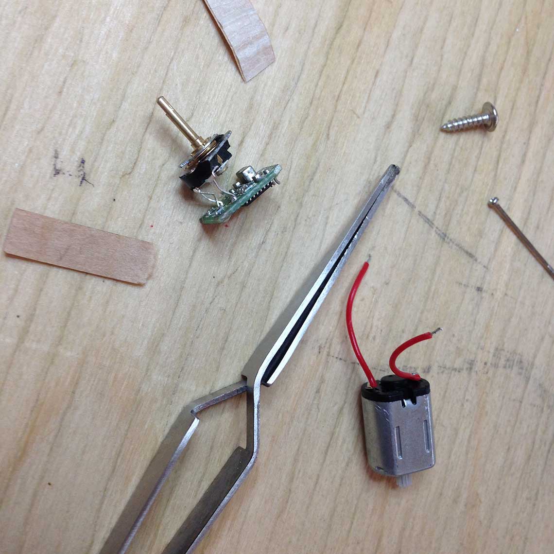
We 3D-printed a pre-made 3D STL file of such a pump. Result is quite good! To complete the system, we bought some plastic tubes and some motors capable to make the pump turn. We began to buy 2 motors for testing.
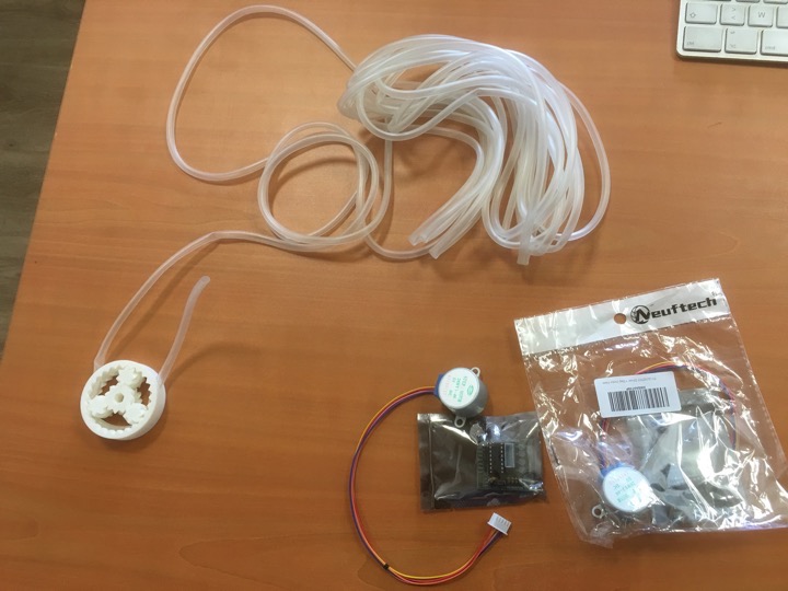 This solution is quite economic as well (aroud $10 per motor, same for tubes) and it solves potential sealing problems... because the liquid is pumped and not always under gravitational force.
Part 2 : Machine design
Electronics
For the electronics, we made a little to-do list :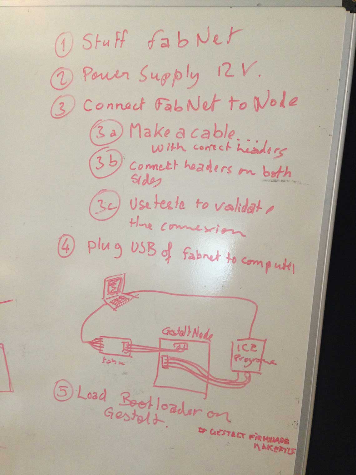 In the kit we received from Fab Foundation, we already have one Gestalt board per motor. We will use only one motor so only one Gestalt node. The only thing we will have to do is to make the "FabNet" board, which will allow us to connect a computer to the node to control it. We found the schematics here.
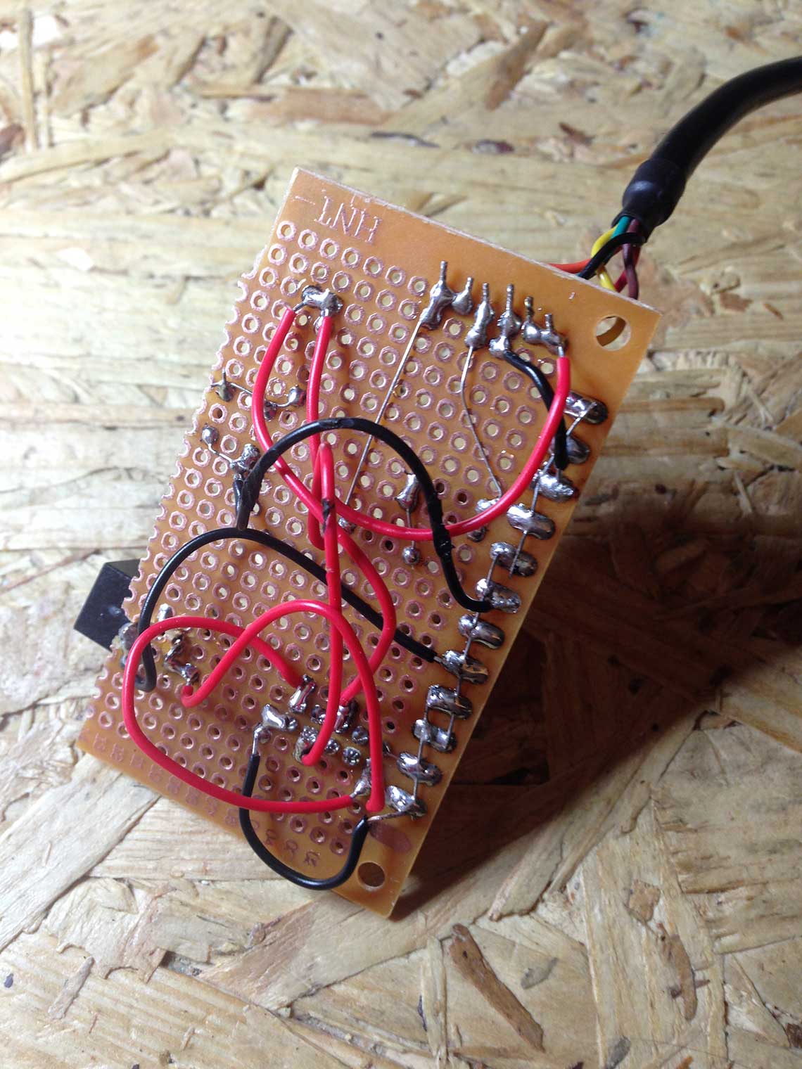
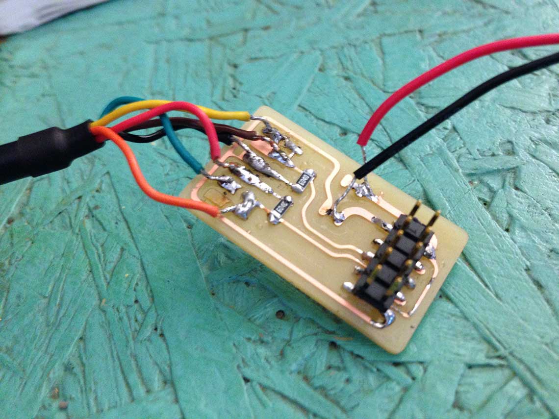
Since none of the milling machines (small one not ready, big one booked all day), we made a THD board so it took quite some time. Here it is :
In the kit we received from Fab Foundation, we already have one Gestalt board per motor. We will use only one motor so only one Gestalt node. The only thing we will have to do is to make the "FabNet" board, which will allow us to connect a computer to the node to control it. We found the schematics here.
Since none of the milling machines (small one not ready, big one booked all day), we made a THD board so it took quite some time. Here it is :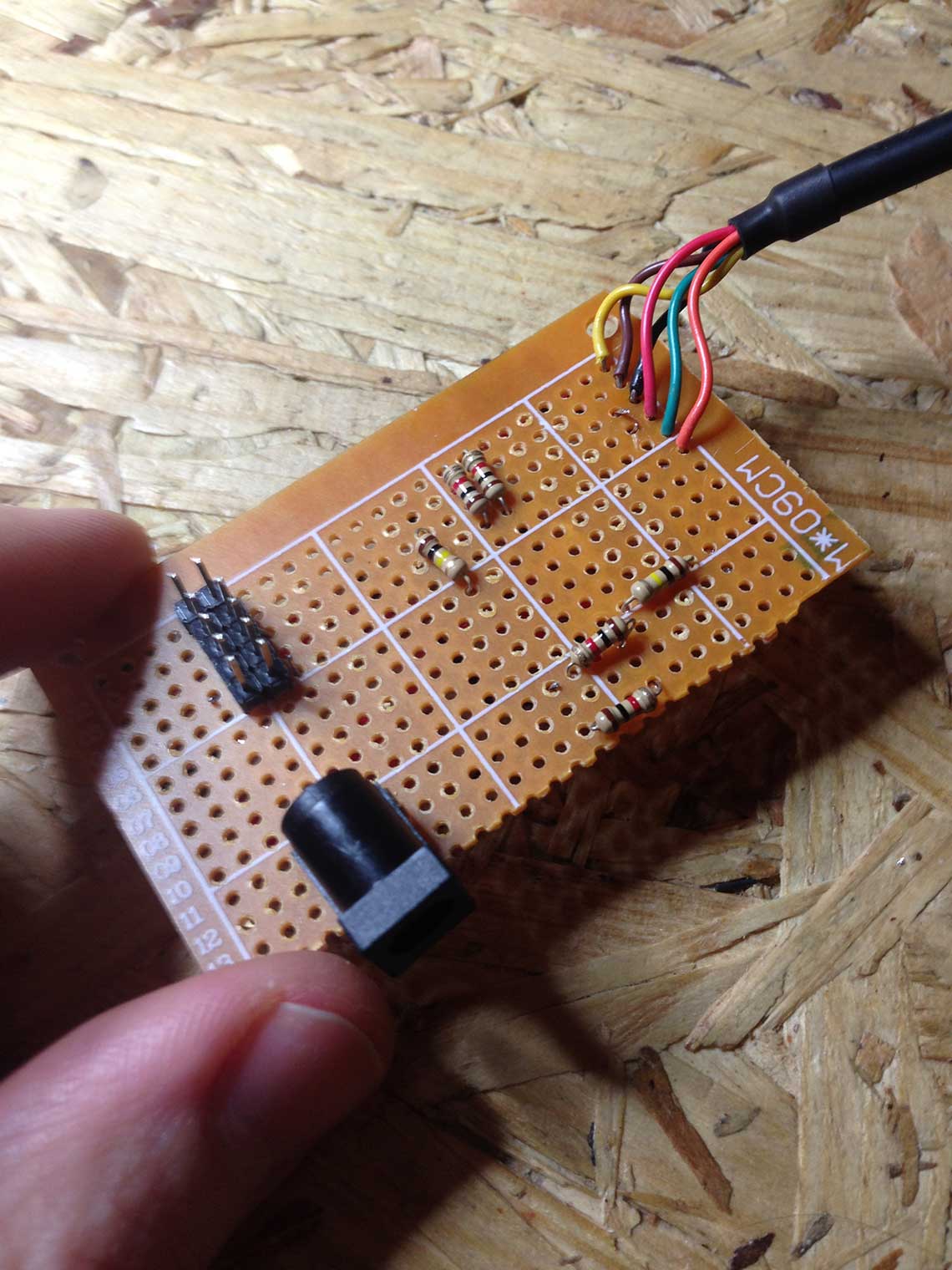
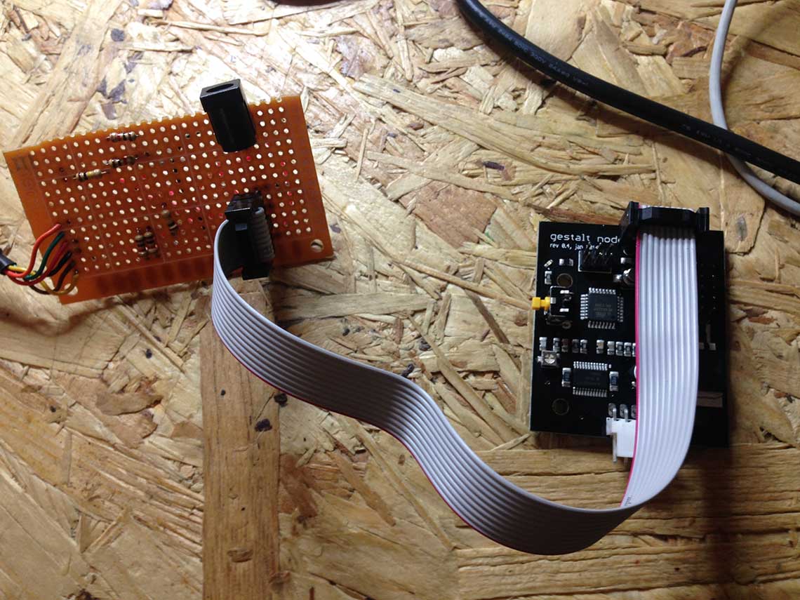 We will be using a Raspberry Pi connected to the Fabnet to be able to pilot the machine remotely by charging the code in it. We will also install a webserver on the Raspberry to be able to is it for the interface of the machine. But as a first step we just tested the connection with a computer.
After this we connected the Fabnet to Gestalt Node and then to USB and power and the boards were overheating, so something must be wrong on the boards. Now the CNC was available we decided to mill a FabNet board. For this we used Bas' version that can be found here. Here is the new version of the board, milled and soldered !
 Next step was to see if we were able to communicate with the Gestalt from a computer and try to operate it. After a few unsuccessful tries we realised the FTDI cable was plugged the wrong way on the Gestalt, so we changed it and then it worked !!
Here is a screenshot of the successful program ran into the Terminal :

Programming
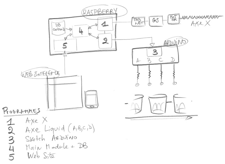
We've done a sketch of all mechanical functions and how they are controlled by electronics and embedded programs.
 Some explanations... :
- As explained above, we chose to use a Raspberry Pi to manage the main functions of the machine : on the one hand, the Raspberry is controling the FabNet / Geshalt / X motor node, and on the other hand, the Raspberry is controlling the Liguid distribution system via an Arduino electronic interface.
- The machine is piloted by web interfaces, thanks to a mini-website and a mini-cocktail-database hosted in the Raspberry
1 - the progam to pilot the X Axis, embedded on the Geshalt via the Fabnet
2 - an interface program between the Raspberry and the Arduino, in order to make the program 3 works.
3 - the 3d program, coded in a Arduino language (Sketch), to pilot the Liquid Distribution System, and to control the End-stop machine.
4 - the 4th program is the core program in the heart of the Raspberry ; it ensures the treatments of the input data and distributes the command lines between programs 1 and 2. And "vice versa", the 4 program takes the information about liquid distribution process and output the results in the web interface - the 5th program.
5 - The Human-machine interface is done by a mini-website and a mini-cocktail database hosted in the Raspberry.
We decided to realize everything in micro-service architecture so each component may be used and developed separately. Each component above (python) are realized as web server responding on kind of REST API interface with few methods.
Here is the short video of communication with brain component that is in center of all micro-service architecture. This brain component call x-axis and l-axis components to ask move to correct position and ask to serve liquid in requested amount. In the video below I execute 2 requests - first is to brain module to ask to serve: small&glasses={"1": {"water": 10, "whiskey": 20}, "3": {"soda": 40}} - that mean I need in small glasses range deliver into first glass - 10 ml of water and 20ml of whiskey, and then in glass #3 - 10ml of soda. And then I check the status of the machine in "realtime". It looks like this:
We send request for shots:
$ curl "http://localhost:5001/mix?type=small&glasses=%7B%221%22%3A+%7B%22water%22%3A+10%2C+%22whiskey%22%3A+20%7D%2C+%223%22%3A+%7B%22soda%22%3A+40%7D%7D"
Let check how it going processing our request:
 $ curl "http://localhost:5001/state"
added 40.0ml of soda to small glass #3
 $ curl "http://localhost:5001/state"
added 40.0ml of soda to small glass #3
 $ curl "http://localhost:5001/state"
added 40.0ml of soda to small glass #3
 $ curl "http://localhost:5001/state"
ready
One of the difficult part was discovery functionality of gestalt python code. So we did it via exploration existing examples delivered with the library. As well one of the point was that initial "gestalt" python library named "gestalt" and it overridden by standard python library on MacOS X :-). So usage library internally iside project is the solution or switching to new version of library that has corrected name "pygestalt" :-).
    MBP-de-Thomas:htmaa thomasfeminier$ python single_node.py
    single_node.py: Warning: setting persistence without providing a name to the virtual machine can result in a conflict in multi-machine persistence files.
    FABNET: port /dev/tty.usbserial-FTZ56QNH connected succesfully.
    X Axis: http://www.fabunit.com/vn/086-005a.py
    X Axis: RUNNING IN APPLICATION MODE
    X Axis: loaded node from:  086-005a.py
    CONTINUITY CHECK PASSED
    X Axis: ERROR IN BOOTLOADER: CANNOT RESET NODE
    X Axis: Motor current set to: 1.04A
    26
    {'writePosition': 1, 'stepsRemaining': 0, 'readPosition': 0, 'currentKey': 0, 'statusCode': 1}
    {'writePosition': 2, 'stepsRemaining': 216, 'readPosition': 1, 'currentKey': 0, 'statusCode': 1}
    {'writePosition': 3, 'stepsRemaining': 196, 'readPosition': 1, 'currentKey': 0, 'statusCode': 1}
    {"writePosition": 3, "stepsRemaining": 159, "readPosition": 1, "currentKey": 0, "statusCode": 1}
    {"writePosition": 3, "stepsRemaining": 117, "readPosition": 1, "currentKey": 0, "statusCode": 1}
    {"writePosition": 3, "stepsRemaining": 95, "readPosition": 1, "currentKey": 0, "statusCode": 1}
    {"writePosition": 3, "stepsRemaining": 54, "readPosition": 1, "currentKey": 0, "statusCode": 1}
    {"writePosition": 3, "stepsRemaining": 34, "readPosition": 1, "currentKey": 0, "statusCode": 1}
    {"writePosition": 3, "stepsRemaining": 214, "readPosition": 2, "currentKey": 1, "statusCode": 1}
    {"writePosition": 3, "stepsRemaining": 174, "readPosition": 2, "currentKey": 1, "statusCode": 1}
    {"writePosition": 3, "stepsRemaining": 149, "readPosition": 2, "currentKey": 1, "statusCode": 1}
    {"writePosition": 3, "stepsRemaining": 106, "readPosition": 2, "currentKey": 1, "statusCode": 1}
    {"writePosition": 3, "stepsRemaining": 86, "readPosition": 2, "currentKey": 1, "statusCode": 1}
    {"writePosition": 3, "stepsRemaining": 48, "readPosition": 2, "currentKey": 1, "statusCode": 1}
    {"writePosition": 3, "stepsRemaining": 27, "readPosition": 2, "currentKey": 1, "statusCode": 1}
    {"writePosition": 3, "stepsRemaining": 207, "readPosition": 3, "currentKey": 2, "statusCode": 1}
    {"writePosition": 3, "stepsRemaining": 169, "readPosition": 3, "currentKey": 2, "statusCode": 1}
    {"writePosition": 3, "stepsRemaining": 149, "readPosition": 3, "currentKey": 2, "statusCode": 1}
    {"writePosition": 3, "stepsRemaining": 110, "readPosition": 3, "currentKey": 2, "statusCode": 1}
    {"writePosition": 3, "stepsRemaining": 68, "readPosition": 3, "currentKey": 2, "statusCode": 1}
    {"writePosition": 3, "stepsRemaining": 46, "readPosition": 3, "currentKey": 2, "statusCode": 1}
    {"writePosition": 3, "stepsRemaining": 5, "readPosition": 3, "currentKey": 2, "statusCode": 1}
    MBP-de-Thomas:htmaa thomasfeminier$
    MBP-de-Thomas:htmaa thomasfeminier$
For debug purpose we defined a special module debug.py (accessible in git). It permit to execute some commands from python command line.
$ python
Python 2.7.10 (default, Nov 11 2015, 16:14:53)
[GCC 4.2.1 Compatible Apple LLVM 7.0.0 (clang-700.1.76)] on darwin
Type "help", "copyright", "credits" or "license" for more information.
>>> import debug
>>> x=debug.xNodeController()
debug.py: Warning: setting persistence without providing a name to the virtual machine can result in a conflict in multi-machine persistence files.
FABNET: port /dev/tty.usbserial-FTZ56QNH connected succesfully.
X Axis: http://www.fabunit.com/vn/086-005a.py
X Axis: RUNNING IN APPLICATION MODE
X Axis: loaded node from:  086-005a.py
CONTINUITY CHECK PASSED
X Axis: ERROR IN BOOTLOADER: CANNOT RESET NODE
X Axis: Motor current set to: 1.04A
>>> x.stage.move([10], 1000)
......
To drive the machine we installed RaspberryPI model 2 near by the machine. On the raspberry we have all required components and running nodejs provided Web interface. This model contain enough USB ports to manage machine drive (gestalt FabNet) and arduino to manage Liquid-axis.
Here is the Arduino sketch that we used to pilot the stepper motors that control the taps :
    #include
    #define HALFSTEP 8

    // Motor pin definitions
    #define motor1Pin1  8      // IN1 on the ULN2003 driver 1
    #define motor1Pin2  9      // IN2 on the ULN2003 driver 1
    #define motor1Pin3  10     // IN3 on the ULN2003 driver 1
    #define motor1Pin4  11     // IN4 on the ULN2003 driver 1

    #define motor2Pin1  4      // IN1 on the ULN2003 driver 2
    #define motor2Pin2  5      // IN2 on the ULN2003 driver 2
    #define motor2Pin3  6      // IN3 on the ULN2003 driver 2
    #define motor2Pin4  7      // IN4 on the ULN2003 driver 2

    String inString = "";    // string to hold input

    boolean connectedMotors = true;  // To be changed on true when motors are connected and on false when used just for debug
    boolean debug = true;     // Some debug output can be activated here

    int open_dist = 1500;
    int measurement[16]={0,2000,2500,3000,4000,5500,7000,8500,10000,11500,13000,14500,16000,17500,19000,20500}; // Array to match duration (in ms) with quantity (in cl) - quantity as index of the array

    // Initialize with pin sequence IN1-IN3-IN2-IN4 for using the AccelStepper with 28BYJ-48
    AccelStepper stepper1(HALFSTEP, motor1Pin1, motor1Pin3, motor1Pin2, motor1Pin4);
    AccelStepper stepper2(HALFSTEP, motor2Pin1, motor2Pin3, motor2Pin2, motor2Pin4);

    void setup() {
      stepper1.setMaxSpeed(1500.0);
      stepper1.setAcceleration(200.0);
      stepper1.setSpeed(200);

      stepper2.setMaxSpeed(1500.0);
      stepper2.setAcceleration(200.0);
      stepper2.setSpeed(200);

      Serial.begin(9600);
      while (!Serial) {
        ; // wait for serial port to connect. Needed for native USB port only
      }
      ready();

    }//--(end setup )---

    void loop() {
       while(Serial.available() > 0) {
        char c=Serial.read(); // Read next char
        inString += (char)c;

        if (c==';') break; // End of command?
        if (Serial.available()==0) delay(5);
       }

      if(inString.length()>2 && !isDigit(inString.charAt(0)) && isDigit(inString.charAt(1)) && isDigit(inString.charAt(2))) { // End of line? Anything received?
          inString.trim();
          if (debug){
            Serial.println("Arduino program output:");
            Serial.print(" On serial string received: ");
            Serial.print(inString);
            Serial.print(" Tap: ");
            Serial.println(inString.charAt(0));
            Serial.print(" Value: ");
            Serial.print(inString.substring(1, 3).toInt());
            Serial.println("cl");
          }
        commandAnalyze();  // Analyze
        ready(); // Ready for next command
      }

      else if(inString.length()>2){
        // No ; or newline?
         Serial.println("Please format string correctly");
         ready();
      } else {
        Serial.print(inString);
      }

    }

    void commandAnalyze() {
      // Command need to be send in following way. <id of tap A, B, C, D.. etc.<>qantity of liquid in centiliters in 1 decimal byte>. Example: A1, A5, B10

      int qnt = inString.substring(1, 3).toInt();
      if (qnt > 15){
        inString="";
        Serial.println("ERROR: We can not serve more then 15 centiliters");
        sendERROR();
        return;
      }

      if (qnt < 1){
        inString="";
        Serial.println("ERROR: We can not serve less then 1 centiliter");
        sendERROR();
        return;
      }
       if(inString.substring(0,1) == "A"){
        if (debug){
          Serial.println(" Open/Close tap A");
          Serial.print(" For duration: ");
          Serial.print(measurement[qnt]);
          Serial.println("ms");
        }
        tap_A_open(measurement[qnt]);
        sendOK();
       } else  if(inString.substring(0,1) == "B"){
        if (debug){
          Serial.println(" Open/Close tap B");
          Serial.print(" For duration: ");
          Serial.print(measurement[qnt]);
          Serial.println("ms");
        }
        tap_B_open(measurement[qnt]);
        sendOK();
       } else {
          Serial.println("Only taps A and B are supported");
          sendERROR();
       }
       inString="";
    }

    void sendOK() {
      Serial.println(F("<ok>"));
    }

    void sendERROR() {
      Serial.println(F("<error>"));
    }

    void ready() {
      inString="";
      Serial.print(F(">>>\n"));  // ready to receive input
    }

    void tap_A_open(int duration) {
      if (connectedMotors){
        stepper1.moveTo(open_dist);
        while(stepper1.distanceToGo() != 0) {
          stepper1.run();
        }
      }
      delay(duration);
      if (connectedMotors){
        stepper1.moveTo(0);
        while(stepper1.distanceToGo() != 0) {
          stepper1.run();
        }
      }
    }

    void tap_B_open(int duration) {
      if (connectedMotors){
        stepper2.moveTo(open_dist);
        while(stepper2.distanceToGo() != 0) {
          stepper2.run();
        }
      }
      delay(duration);
      if (connectedMotors){
        stepper2.moveTo(0);
        while(stepper2.distanceToGo() != 0) {
          stepper2.run();
        }
      }
    }
This program drives the stepper motor, 1000 steps in a direction, then 1000 steps in the other direction. We used it to test the join/box mount as you can see in the video below :We use the serial monitor to pilot the distribution of liquid. Here is a test video where you can see the process :
And once the motor mounted on the machine and connected to the machine, it looks like this !:
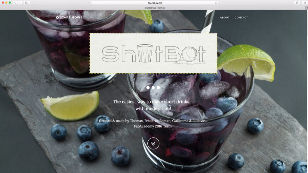
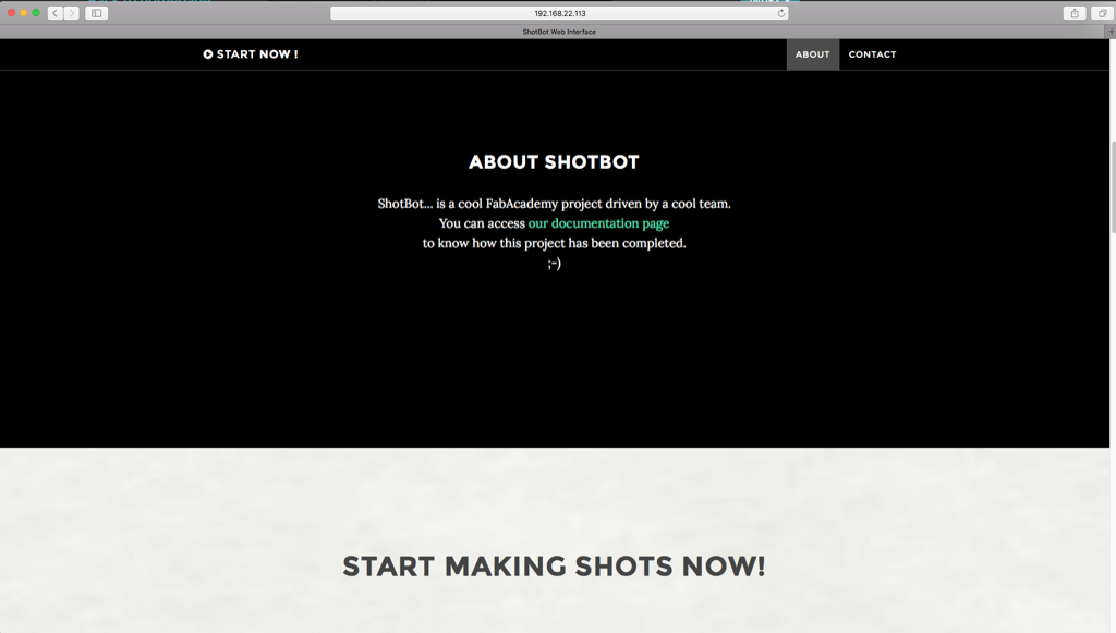
The Human-machine Interface
Website to make an interface between human and the machine we developed in nodejs express using the bootstrap theme. This interface will permit in few steps order the shots using the simple and visual process of selection.
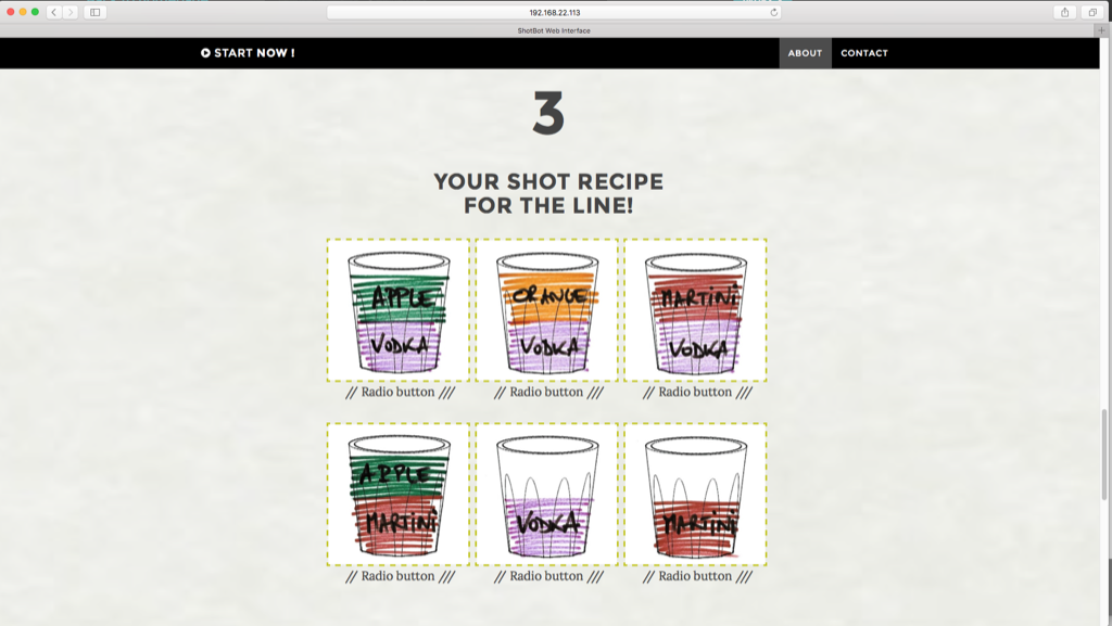
Main features :
- Number of glasses on the plate
- Small (10cl) or big glasses (25cl)?
- Number of glasses on the plate (5 max fpr small glasses, 4 mx for big glasses)
- Kind of shot: choose among the 4 liquids (to get a sigle alcoholc liquid shot) or choose between a combination of available liquids (for multi-layers alcoholic liquid shot) ?
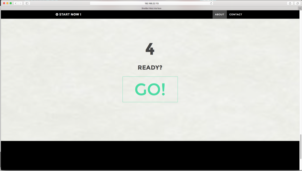
- "GO" button, "In progress" progression bar, and "shots ready" alert on the screen
Technical aspects :
- A HTML responsive website for a multi-screen usage
This part is not completely finished yet but will be soon.