Mechanical design
Week 10's assignment
Specific material and softwares used during this assignment
- Machines and electronics :
- Laser cutter for the structure
- CNC mill for the FabNet
- 3D printer for the tap system
- One Arduino board and One raspberry Pi to control the "l axis"
- Material :
- 5mm cardboard and 5mm plywood
- PLA
- Software :
- Rhino for the design of the machine and the 3D parts
- Cura for the 3D printed parts
- Atom for programming
- Arduino IDE for arduino sketches
- Other equipment :
- Silicon tubes
- Plastic taps (for acquarium aeration systems)
- Plastic connectors (for acquarium aeration systems)
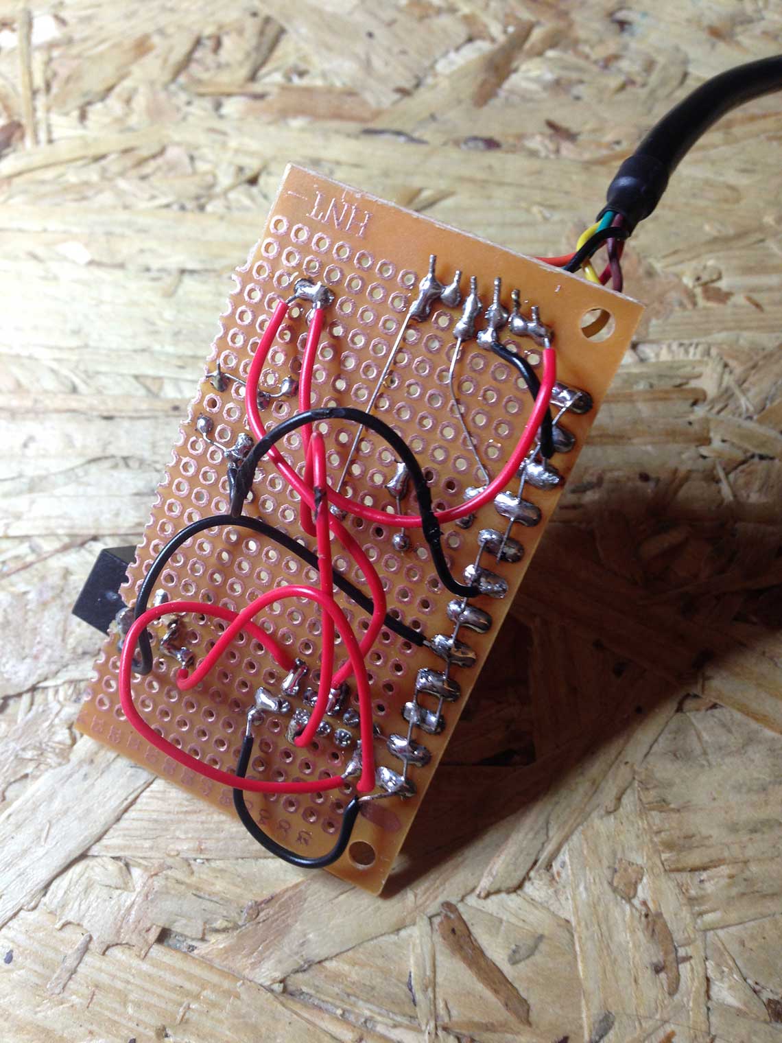
I also worked on the fabrication of the FabNet board. Since none of the milling machines (small one not ready, big one booked all day), we made a THD board so it took quite some time. I soldered all the components, made the alimentation cable that works with a rack of 8 batteries of 1.5V. Here it is :

 After this we connected the Fabnet to Gestalt Node and then to USB and power and the boards were overheating, so something must be wrong on the boards. Now the CNC was available we decided to mill a FabNet board. For this we used Bas' version that can be found here.
Here is the new version of the board, milled and soldered !
After this we connected the Fabnet to Gestalt Node and then to USB and power and the boards were overheating, so something must be wrong on the boards. Now the CNC was available we decided to mill a FabNet board. For this we used Bas' version that can be found here.
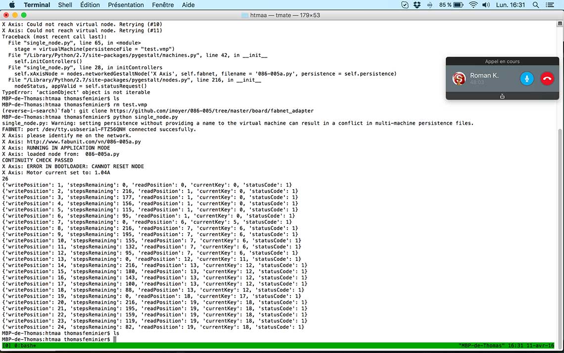
Here is the new version of the board, milled and soldered !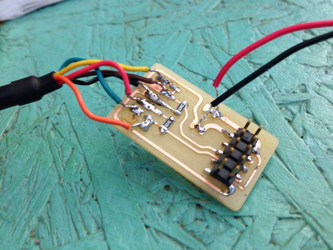 Next step was to see if we were able to communicate with the Gestalt from a computer and try to operate it. After a few unsuccessful tries we realised the FTDI cable was plugged the wrong way on the Gestalt, so we changed it and then it worked !!
Here is a screenshot of the successful program ran into the Terminal :
Then I did some other tests to determine the total distance we had for the movements of the head. The easier way to do it was to mark down the coordinates used in gestalt on a piece of tape like this :
 We know that when we change the coordinates of 10 points, it actually represents 1.3cm. This will be important to know for the rest.
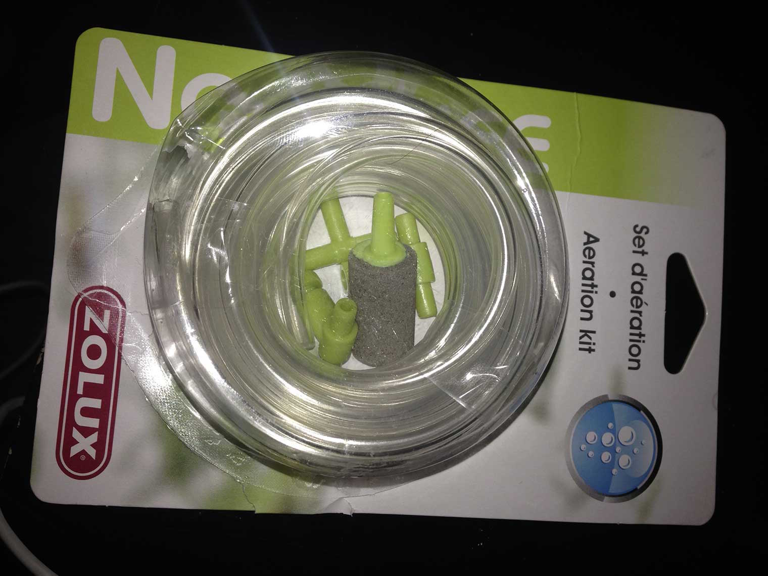
For the Liquid Distribution system, I also participated to the research on the mechanical part : the aim was to find the best way to deliver the liquid and we finally came up with the idea of using a tiny tap bought at a pet shop and initialy made for air distribution in fish tanks. This is the kit that we bought :
 And those are the tap and the connector for the tubes :
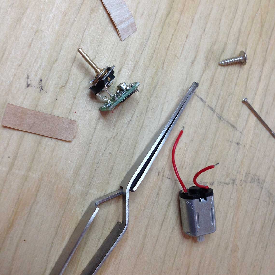
 So the idea is to connect directly a servo-motor to the taps to open and close them. For a tap to be open, we must apply a 900° rotation to the screw. So in order to do that we would have to modify the servo-motor to suppress its rotation limit. We found this tutorial on instructables to do this and I wanted to try :
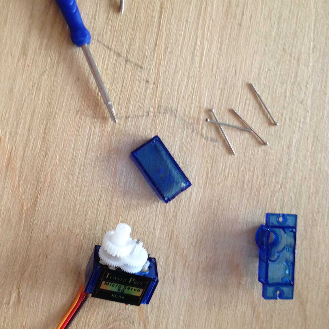

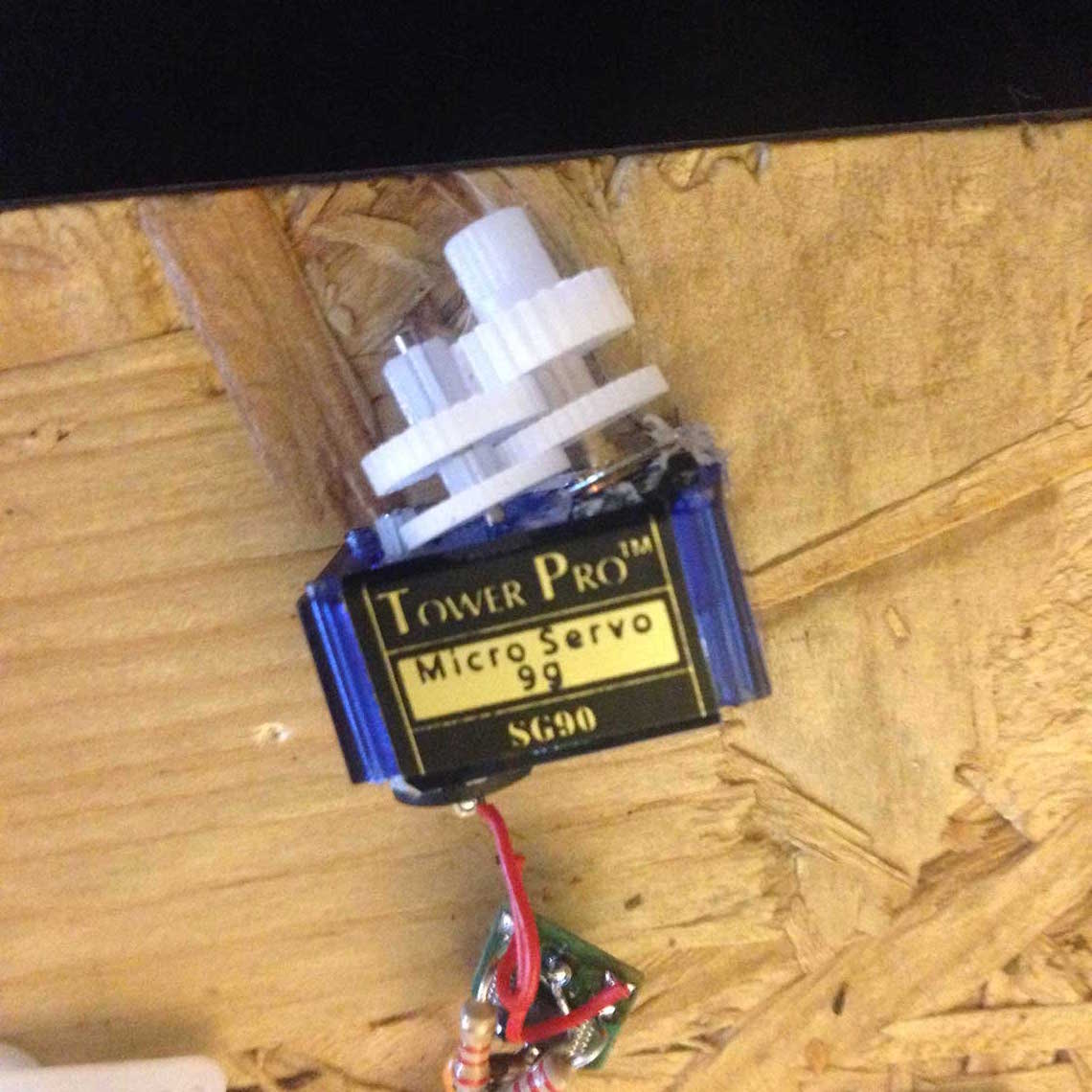
We had no more servo to destroy at the lab, so we decided we would continue with a stepper motor instead.
See the Group Page for the next steps of the programming and human/machine interface.