Week Four: Electronic Production
My goal this week is to design my own curcuit board, have it connected to a laptop, and run a program to test whether this work. Everything has a first step, and this first step is to use Roland Milling Machine to cut a board, I choose the project of Valentine. I download the three files from the website of FabAcademy. I use the online version of FabModule to sketch the lines that I need to cut. The traces for cutting can be devided into two types. One is to make the shapes that are needed for soldering. The other is to cut off unnecessary parts of the PCB board. Regarding the parameters on FabModule, I largely leave the numbers to the default, and I set the parameters of xyz axis to 0.
-
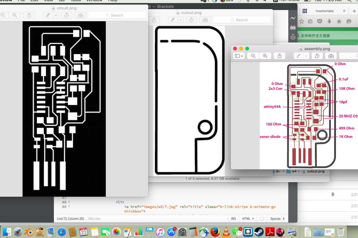
Step1: Download the files that I need
-
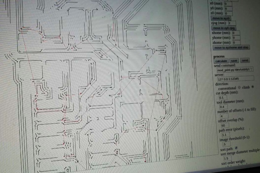
Step 2: Use fabmodule to run the milling machine
-
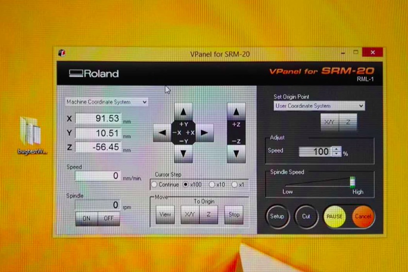
Step 3: Use Vpanel to execute the mission for milling machine
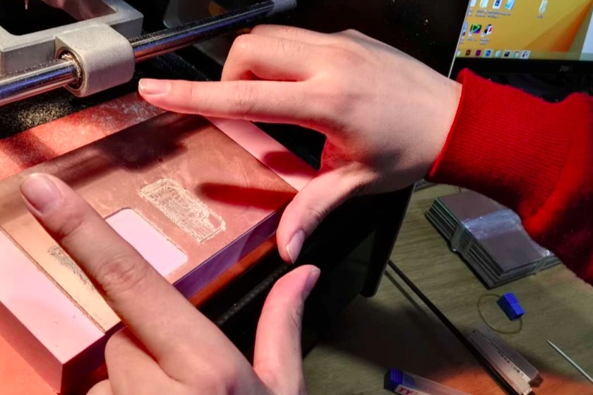
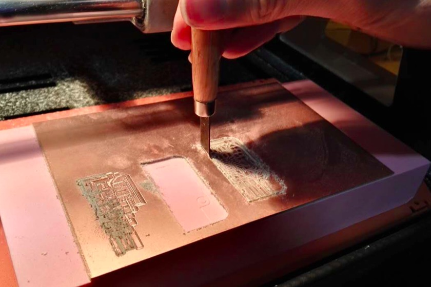
One can see from the image how the milling machine works. Before running the machine, I need to switch the end to the right size: 1/64 for milling the board, and 1/32 for cutting the board. I need to use a small gear to loosen the end for the endmill. the whole process has to be done with care in order not to break the endmill, which is very fragile. After having the board cut, I use a small knife to get the part out of the whole trunk.
-
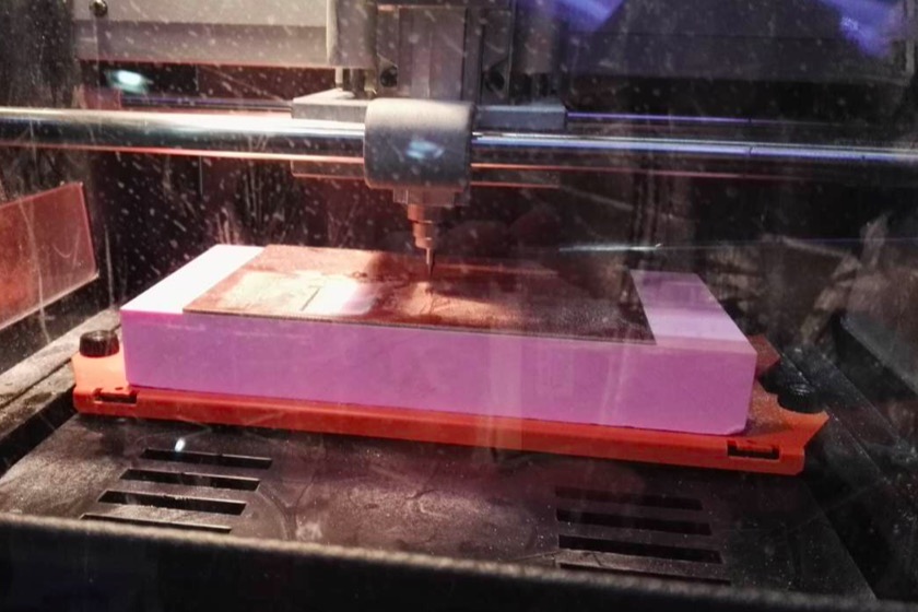
Step 4: How does the milling machine function
-
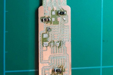
Step 5: The outcome
-
Step 6: Use a knife to cut out the board
For the success of making a good circuit board, I decide to do some practice to get familiar with the tool. There are several tools to be introduced: soldering tools, a nip, manifier lens and many other things. There are several tips that can improve the successfulness of getting a component soldered: I. when I start, I first put my solder on a spot before actually anchoring a component on that spot; II. I have to make my component at the right position in order to have it well-soldered; III. when two solders get sticked together, a situation that is not supposed to be, I use my soldering pen to do an upward move in order to split the connection. You can see in the step 9, the final outcome of my practice, which is not too bad for a beginner, I assume.
-
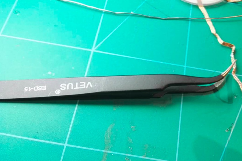
Step 7: Here is a nip
-
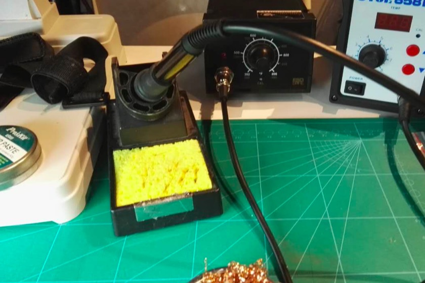
Step 8: Here is a soldering pen
-
Step 9: The practice
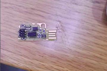
The soldering of the actual project is of the same procedures with a little bit more difficulty. One additional preparation under the guidance of Anders is to have my components listed and taped on a paper before I start my actual work. Then I do it one by one just as how I appraoch my practice.
-
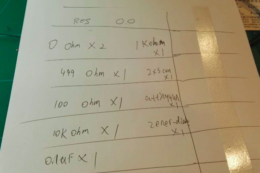
Step 10: The preparation of a component sheet
-
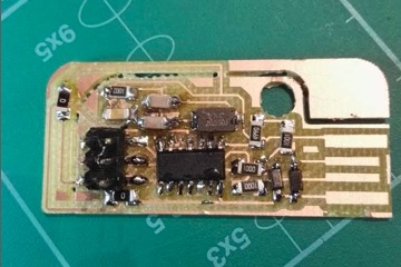
Step 11: The outcome of my valentine board
-
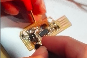
Step 12: The demonstration of my final integrated piece
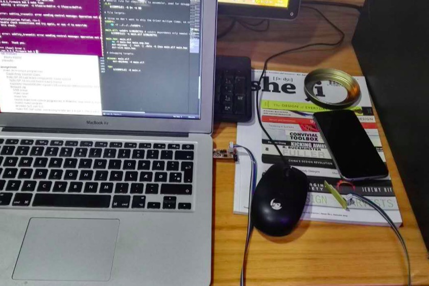
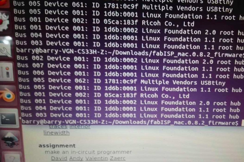
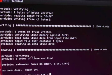
There are several things to do before I actually test my valentine board. I use a traditional tool in Chinese labor classroom to help me make my wire. I split six tiny wires from the combo, and make two ends on both sides. After that, I break apart the unnecessary part of my valentine board, and test it on a linux. I type the "lsusb" in the terminal of linux, and see a positive result of my board. In fact, there was some tiny issue with my board, and I managed to have all of them solved through using the multimeter to tell whether there is a shortcut in places that are not supposed to be.
-
Step 13: Test the valentine board
-
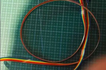
Step 14: Make the wire
-
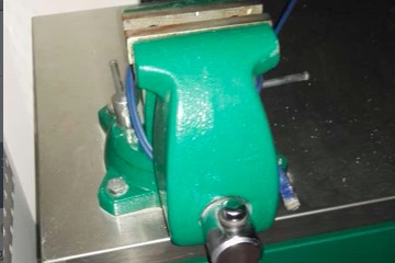
Step 15: I anchor the end of the wire through this tool
-
Step 16: Outcome
-
Step 17: The test result on Ander's laptop
-
Step 18: The test result on my laptop