Study archive - Week 8
Embedded programming
The lecture 8 on Wednesday 16.3 was about programming a microcontroller. I learned about AVR processors and AVR programming languages and environments. The task of the week is to program the board and for this it is important to start with reading the microcontroller datasheet to know what the microcontroller can do and how.
Planning the task
1. The board to program: echo hello-world
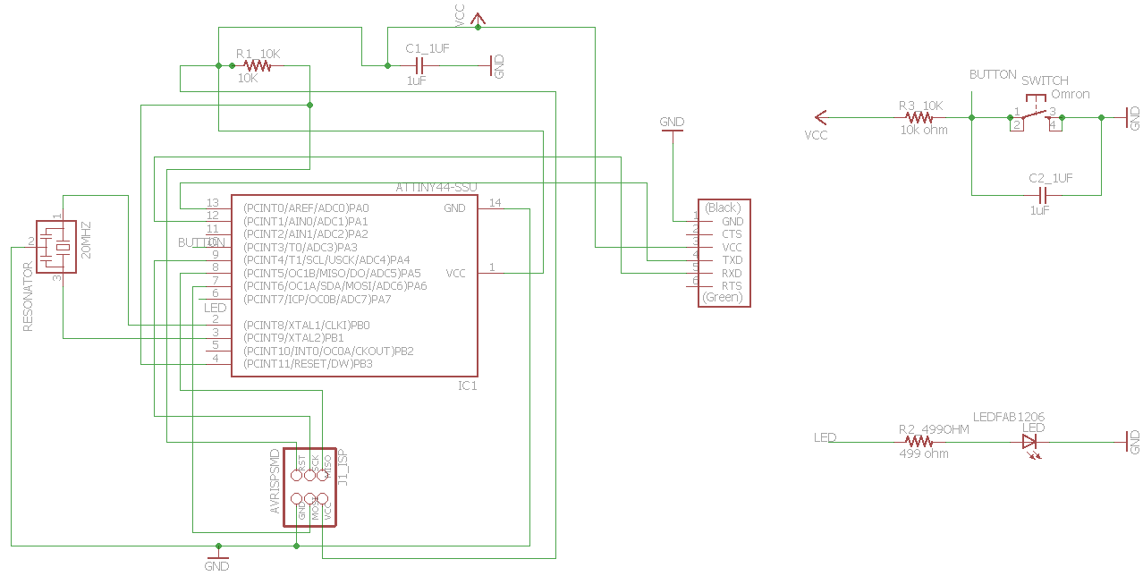
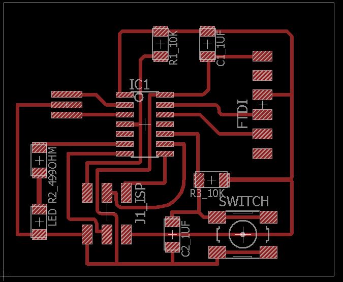
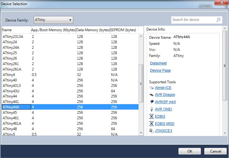
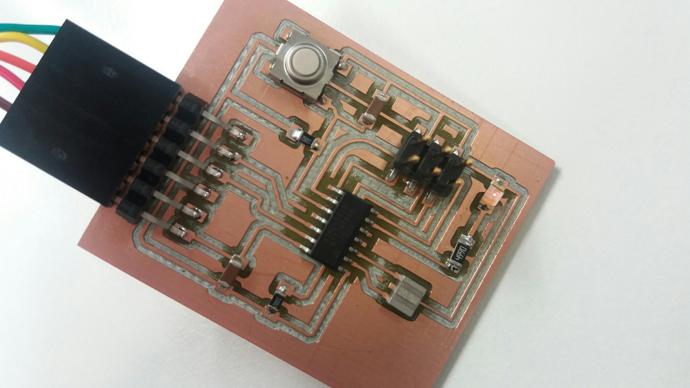
The echo hello-world board I have created in Week 6 consists of a microcontroller ATtiny44A, a crystal resonator (20 Mhz), three resistors (2 x 10k ohm and 1 x 499 ohm), two capacitors (1uF), an USB serial port (FTDI for communication with computer), and an ISP connector (for programming the board), a switch and a led. The schematic and board show how the led and button are connected to the microcontroller, power supply and ground. Thus, the ATtiny 44A PA7 pin is connected to the led, and PA3 to the button. The button is connected to ground when pressed (this means that PINA for PA3 is 0 when button is pressed; viceversa, when button is not pressed PINA PA3 is 1).
2. The hardware resources needed
For programming the echo hello-world board I need the following hardware:
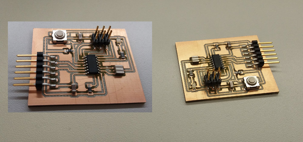
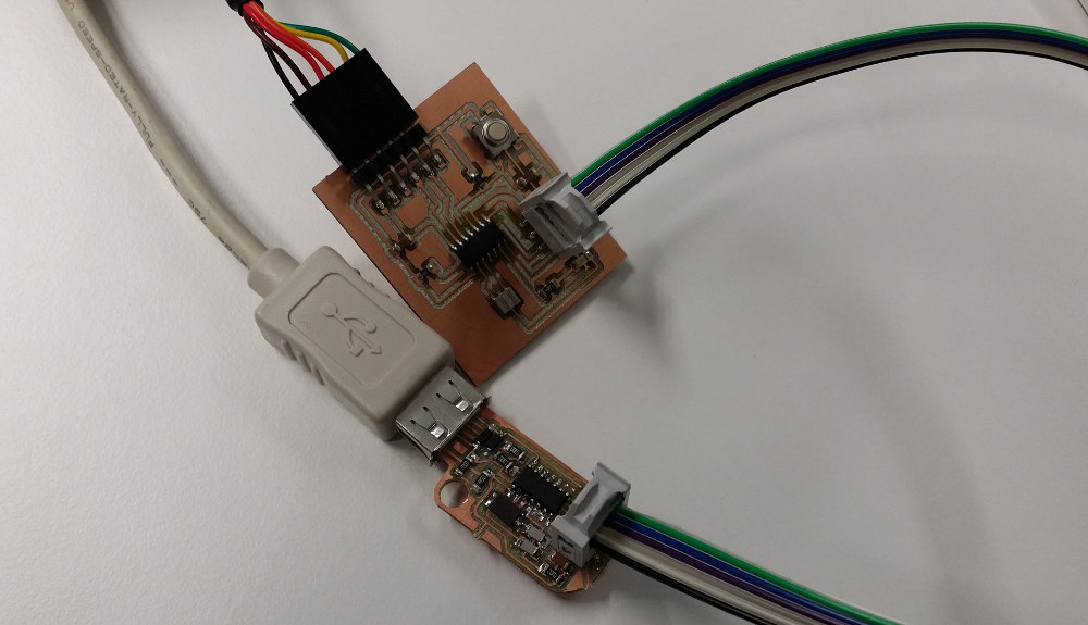
- An ISP programmmer board (this is the board created in Week 4 in Electronics production study week; see picture below). This type of board is called Tiny AVR Programmer or USBtiny and it is a kind of ISP USB board that is used to program chips on other boards using the ISP connection (for reference see this tutorial). There are different ways to create this kind of USBtiny boards (for example, at Fab Academy, we had 4 alternatives to choose from: Valentin, David, Andy, and Zaer - see week 4 lecture); In addition, some types of Arduino boards or other commercial boards can be used for the same purpose as USBtiny.
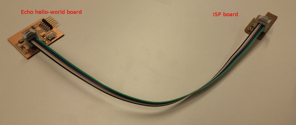
- A 6-wire cable for connecting the USBtiny and the echo hello-world board (I have created this in Week 6 - Electronics design; see picture below).
- Optionally it is recommeded to have a USB connector cable instead of inserting the USBtiny board directly in the computer's USB port.
- An FTDI connector cable for connecting the computer with the echo hello-world board to provide power to it. I got this from the FabLab Oulu; the name of the cable is USB to TTL serial cable (5 V) - 1.8 m.
The main steps
- Installing the drivers for the hardware.
- Reading the datasheet for microcontroller ATtiny44A.
- Programming the echo board with the USBtiny programmer using the code provided in the lecture 8 (i.e, hello.ftdi.44.echo.c).
- Programming the button and led on the echo hello-world board.
1. Installing the drivers
USBtiny board
The drivers for this board can be downloaded from SparkFun page (see Step 3 and click on the link Tiny AVR Programmer drivers). The same files are also in the SparkFun Github repository.
FTDI USB to TTL serial cable
The FTDI driver installs itselfs automatically when the cable is plugged in the computer (thanks to Windows ;).
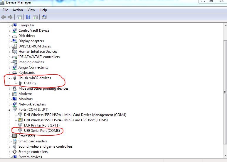
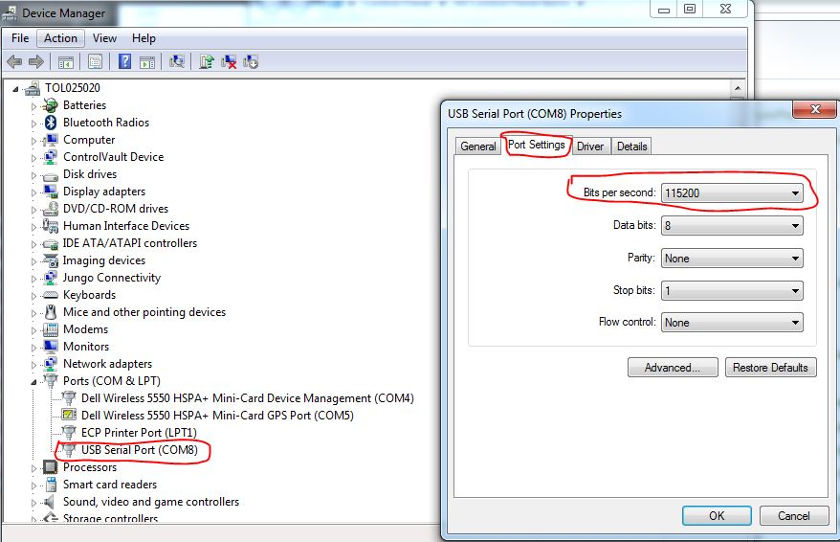
When the drivers are successfully installed, the Device Manager will show two new components in the device list.
2. Reading the datasheet for microcontroller ATtiny44A
I started with reading the datasheet for the FTDI TTL to USB Serial Converter cable from here. The information was useful and interesting; I learned about the wires colors and that this cable is a smart cable that has a memory and processor. The purpose of the cable is to convert TTL signals to USB and the other way around, making possible the commnication and conversion of i/o signals. Also the page on Sparkfun is useful to learn about FTDI cable (see here).
From the ATtiny44A datasheet I learned many things, such as that the Flash memory that stores the program has capacity of 4K and can be written/erased up to 10 000 times. ATtiny 44A are microcontrollers using AVR core RISC architecture ("by executing powerful instructions in a single clock cycle ATtiny44A achieves throughputs up to 1 MIPS per MHz allowing the system designer to optimize power consumption vs processing speed." Coding the ATtiny means accessing and writing the 32 general purpose working registers and the 64 i/o registers in the data memory SRAM; two working registers can be accessed in a single instruction which is executed in one clock cycle. The document gives also examples of coding in C and Assembly, and describes all the registers. It is a useful document for reference when programming the microcontroller. In particular, chapter 10 (I/O ports) is useful for understanding the following registers used in this week programming tasks: Data Register PORTx, Data Direction Register DDRx, and the Port Input Pins register PINx.
3. Programming the echo board using hello.ftdi.44.echo.c
Programming has two steps: 1) writing the code, compile it, and building the executable file that can be read by the chip (.hex file); and 2) copying the .hex code into the AVR chip memory. This step is done using the command line AVRDUDE program.
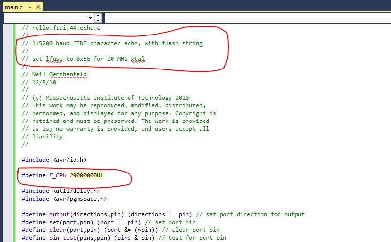
For writing/compiling the code, I have used Atmel Studio 7.0 - an integrated development environment that is used for writing and debugging AVR applications in C/C++ and Assembly. I have used the code provided in the Fab Academy lecture 8 (hello.ftdi.44.echo.c). This program receives input from keyboard and transmits the output (the entered text) on the screen. This communication can be observed in a terminal emulator such as Tera Term or PuTTy. Arduino IDE has its own terminal window for this purpose.
The steps in Atmel Studio are:
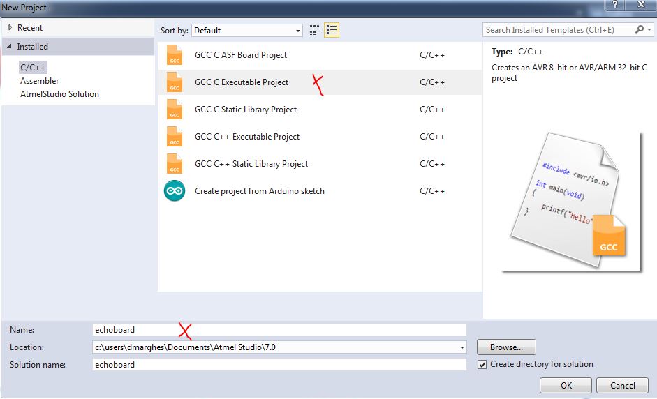
1) Create a project of type "GCC C executable project" and name it e.g., "echoboard".
2) Write the code and save it in the file "main.c".
3) Compile the code (Build > Compile) - the result of this step is the "makefile" and some other files.
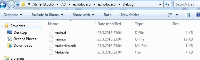
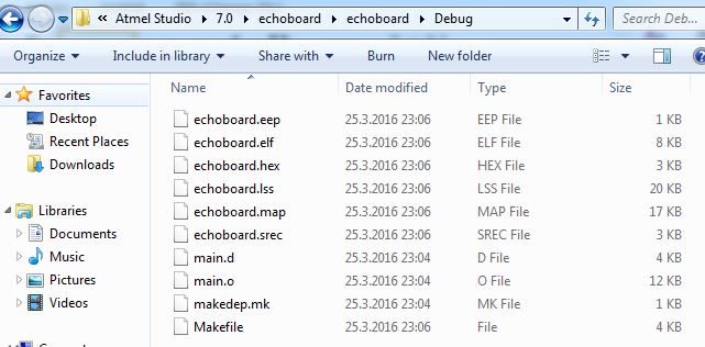
4) Build solution (Build > Build solution) - to obtain the .elf and .hex files. The .hex file will be used to program the board microcontroller.
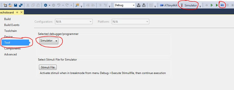
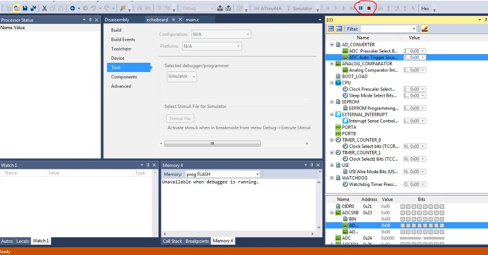
5) Oftentime a Debug step is necessary to fix the eventual logical errors in the built solution. In the solution window, Tool > Simulator. Then Debug > Continue or press the arrow and pause . I have not used this step for the echoboard program.
All the steps above can be done offline, i.e., without plugging in the usbtiny board and the echo board.
The steps in avrdude program
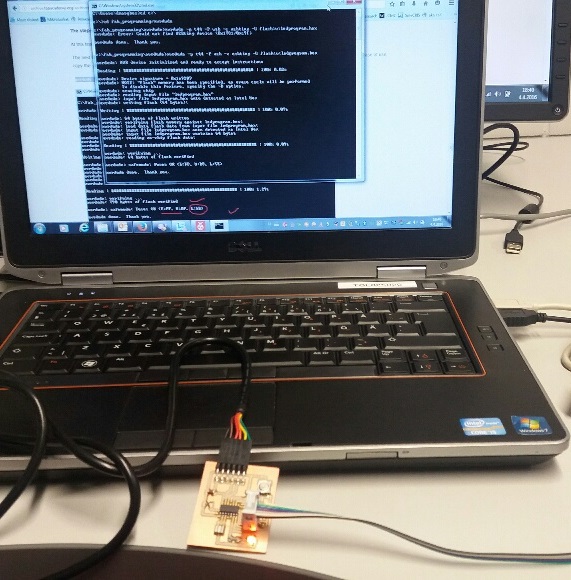
At this time, we have to plug in both the usbtiny board (the AVR programmer) and the echo board (the AVR board to be programmed).
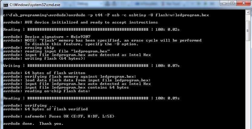
The next command writes .hex file on the ATtiny44A flash memory. This should be done in Windows in the command line editor (cmd.exe). For ease of use, copy the .hex file in the same folder where avrdude.exe file is located.
avrdude -p t44 -P usb -c usbtiny -U flash:w:echoboard.hex
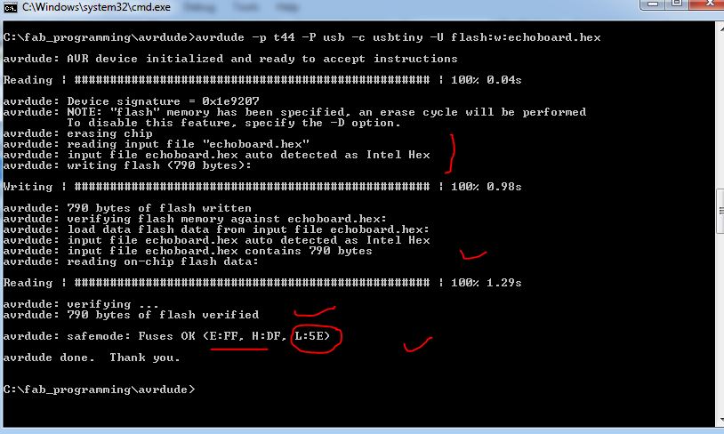
The output of this step shows also the fuses' settings. As shown in Neil's code, the correct low fuse for the 20 MHz should be 0x5E. If the fuses are not the correct ones, programming the fuses is done as follows (e.g., lfuse):
avrdude -p t44 -P usb -c usbtiny -U lfuse:w:0x5E:m
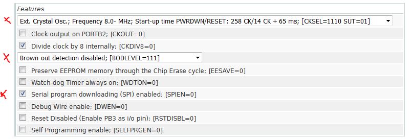
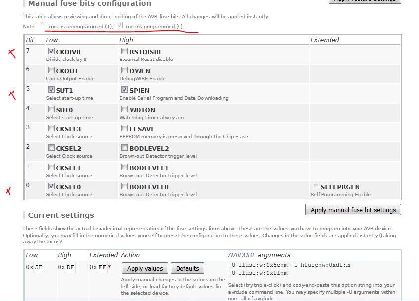
For checking default settings for ATtiny44A fuses and for reviewing other settings see here the fuse calculator on the engbedded.com. For the current settings the selected values are as follows:
After programming fuses and writing the .hex code in the flash memory, the board is programmed. Whenever we power it up (i.e., plug it in the computer using the FTDI cable), it is functional.
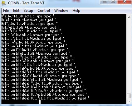
Running the program
Open a terminal emulator (e.g., TeraTerm) and type something to demonstrate what echo board can do.
4. Programming the button and led on the echo hello-world board
Three programs in C are presented below: 1) programming the led to light when the board is plugged in; 2) programming the led to flash at certain time intervals (blinking); and 3) programming the led to light when the button is pressed.
As shown in the schematic, PA7 pin in the microcontroler is connected to the led, and PA3 to the button. The button is connected to ground when pressed (this means that when button is pressed the PA3 will be 0; the current will go VCC - Button - GND and PA3 will have 0 power).
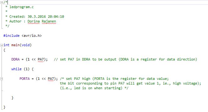
4.1 Light the led when the board is plugged in
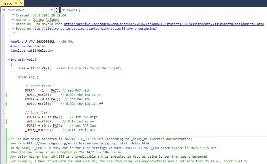
4.2 Flash the led at certain time intervals
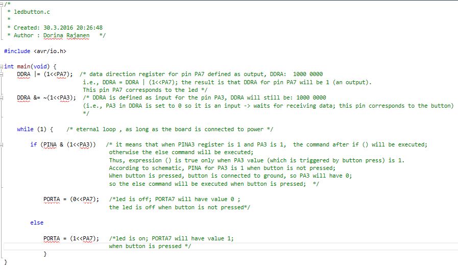
4.3 Light the led when the button is pressed
Some things to remember
- In the programs I have used the command
PORTA = (1<<PA7)which assigns to PORTA the value 1000 0000. In more general cases, when only the bit 7 (corresponding to PA7) has to be changed it is better to use the commandPORTA |= (1<<PA7)which assigns to PORTA the value 1xxx xxxx (where x can be 0 or 1 depending on the previous settings of PORTA). Similarly forPORTA = (0<<PA7)which will results in PORTA = 0000 0000, the more general code will bePORTA &= ~(1<<PA7)which will result in 0xxx xxxx. - The way the cables are connected to the boards: in my case, I follow the rule: "the ISP green wire is always right" (see pic below).
- The baud rate has to be set to 115200 in both Tera Term: Setup > Serial port > Baud rate, and in the Device Manager > Ports > USB Serial Port > Properties (see picture below).
- The Tera Term settings can be saved using Setup > Save setup.
- At first, I had soldered on the PCB a 499K Ohm resistor (by mistake I selected a too powerful resistor), and thus the led did not light properly - the light was hardly visibile. Always check the components before and after soldering (only when Jani checked the PCB, the mistake was found out).
- Another issue was when I set high voltage for PA6 instead of PA7; then the led was lit, but hardly visible (so when a neighboring pin on the microcontroller is set to 1, then there is some effect on other pins: PA6 was leaking electricity to PA7. See picture below.
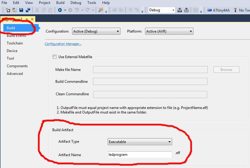
- To open a project in Atmel Studio and to edit there the main.c file; Open existing project in the welcome window, and open the solution file .atsln. Then in Atmel Studio editing environment , File > Open > select the main.c file to open. Then you edit the file, compile and build solution to create the .hex file. You can also rename the .hex file by setting the parameters in Build window (see figure below).
Summary of the week
It was the first time using C language; I have experience with other programming languages, but not C. I learned that C can be used to write code for low-level programming that is used in embedded programming; thanks to the GCC compiler (GNU Compiler Collection) which creates the machine readable files formats such as .hex file.
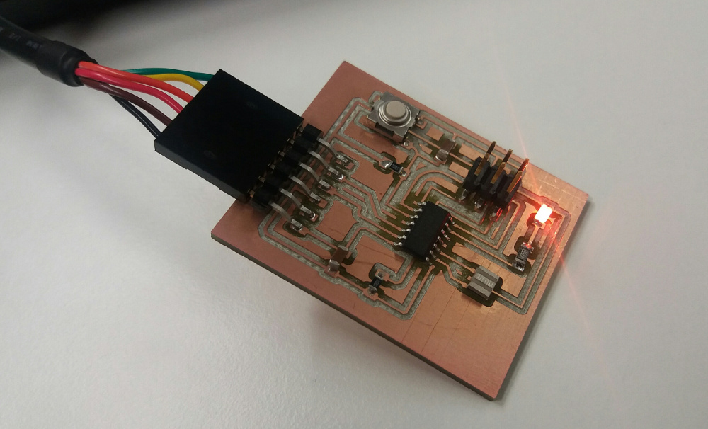
The result is nice! The led turns on when programmed.
Learning resources
- AVRDUDE manual - includes command options descriptions
- SparkFun tutorials - everything you want to learn about electronics, AVR, usbtiny, avrdude...
- An elecrom.com tutorial about i/o pins
- A led-button program explained
- Util/delay.h and _delay_ms documentation
Summary of Tools used
Software
Atmel Studio - for writing/compiling/debugging C code
AVRDUDE - for writing the AVR microcontroller
Tera Term - terminal emulator - for displaying i/o serial communication


