Study archive - Week 3
Computer-controlled cutting
The topics in lecture 3 on Wednesday 10.2 were vinyl and laser cutting controlled by computer.
The tasks of this week are:
- design, make, and document a parametric press-fit construction kit (a set of parts)
- use the vinyl cutter
For the task 1, the idea is to create a 3D object out of multiple 2D parts drawn using a computer-aided design tool; the parts are cutted using a laser cutter and then the parts are joined together to create the desired 3D object. I choose to use Inkscape for designing the 2D parts.
We had nice training and practice sessions in Fablab Oulu of Inkscape, and vinyl and laser cutters. My colleagues at Fablab Oulu, Antti and Juha had nice ideas and built interesting prototypes (click on their names to see their work).
Laser cutting
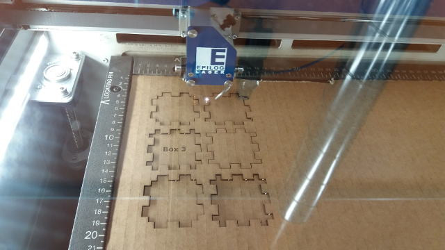
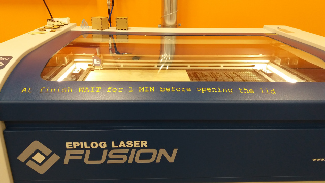
For this task I use Inkscape to model the 2D parts of a cardboard box and a laser cutter machine EPILOG Laser Fusion to make the cuts in the cardboard. I found useful a wiki page that documents the rules of using a laser cutter.
In Inkscape, the models must have the following settings for laser cutting (vector) and engraving (raster):
Settings for laser cutting (vector):
- No Fill
- Stroke paint = black or RGB [0 0 0]
- Stroke style = 0.02 mm and continuous line
Settings for laser engraving (raster):
- Fill = black
- Stroke paint = No stroke (otherwise will also cut the shapes)
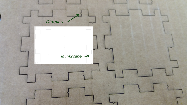
For Inkscape, there is a plug-in Lasercut-box that automates the design of the 2D parts based on given parameters such as size and material thickness. The steps of installing and using the Lasercut-box extension are as follows:
- Download the extension files "Lasercut-box.py" and "Lasercut-box.inx" from https://github.com/Neon22/inkscape-LasercutBox
- Copy the files in the local folder C:/Program Files/Inkscape/share/extentions/
- In Inkscape, open or create a new file. To draw the box, menu Extensions > Render > Lasercut Box...
- In the Lasercut Box dialog window, enter the desired parameters.
- The box parts are now drawn, but if you do not see them, Zoom in to enlarge the image.
The steps for laser cutting/engraving:
- In Inkscape, Save the file with as .pdf and .svg
- Open the .pdf file in Adobe Reader or similar program
- File > Print > Select printer: "Epilog Engraver WinX64 Fusion"; Printing Preferences:
- Select the type of job: Vector / Raster/ Combined
- Enter vector cutting parameters suitable for the material; speed/power/frequency
- Enter Raster engraving parameters suitable for the material; speed/power/frequency
- For predefined parameters click on Load and select from the list
The operation of the laser cutter is 1) power on, air filter system on. 2) set the origin by selecting Jog with up/down arrows. Move the lense head with the joystick to the desired place and press the joystick to set the origin (the upper left corner of the document). 3) set Focus; use the triangle tool and move the laser bed up or down with the joystick until the focusing tool is touching the surface of the material. Press the joystick. 4) if the printing job was sent to the laser cutter, press the Go to proceed laser cutting.
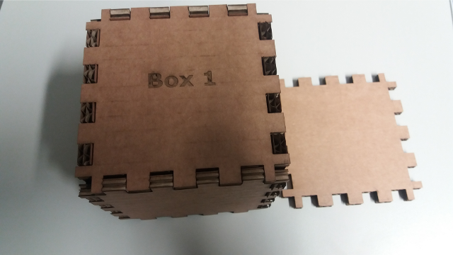
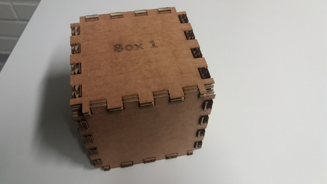
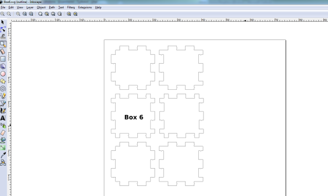
Below I document the settings for the first box, Box 1. The lasercut-box parameters: Size 100x100x100 mm. Material thickness 7,83 mm. The tab counts for width, height and depth: 4x4x4 mm. The laser kerf: 0.1 mm. No dimples.
Laser cutting/engraving parameters:Two steps because it did not cut the cardboard from the first time (First step is with engraving text and the second without engraving)
- Raster engraving: Speed 15/ power 10/ frequency 50; Vector cutting: Speed 25/ power 45/frequency 50;
- No Raster engraving: I deleted the text in the original .svg file in Inkscape, and saved a new .pdf; Vector cutting: speed 20/ power 20/ frequency 50
These settings produced too loose joints. One reason can be that the material thickness in the lasercut-box was 7.83 mm, which did not correspond to reality (cca 6 mm). Another reason can be the setting of the kerf to 0.1 mm. The kerf represents the lost material when laser cutting (due to burning). A zero value produces a loose fit of the parts that would require glue to hold the parts well. A higher value than 0 can produce precise fit or press fit. For press fit, you have to add also Dimples if the material is flexible (e.g, cardboard).
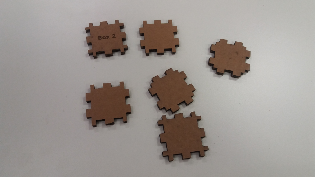
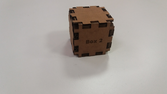
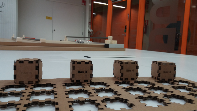
For Box 2, I used some instructions for Press-fit kit settings from here. I calculated the kerf to 0.16 mm, thus I used kerf = 0.2 in the second box and also Dimples. Material thickness = 5.6 mm. I changed also the size of the box to 50x50x50 mm, with 2x2x2 tabs (notches). The settings for vector/raster cutting were: step 1) raster: 15/10/50 and vector: 25/40/50; step 2) vector: 20/30/50. Box 2 was slightly better than Box 1, but still the joints were too loose.
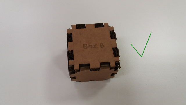
For Box 3, I increased the kerf to 0.4 mm. The result was again not satisfactory; still too loose joints. A Box 4 was created with material thickness 6 mm and kerf 0.6 mm. The result was a bit better, but still could be improved. For Box 5, with thickness 5.6 mm and kerf 0.6 mm, I changed the cutting settings in both steps to 20/30/50. The result was again disapointing. Finally, the best result was Box 6 with thickness 5 mm and kerf = 0.6. In both steps, the cutting parameters were for vector 25/30/50 and for raster 15/5/50.
The summary of laser cutting:
- The material thickness is important for obtaining tight joints. It is better to set a thickness lower than the real value (instead of higher than the real value).
- The laser kerf is better to be higher. If there are many steps of cutting (e.g., the material is thick), then a higher value is better. For the task, 0.6 mm was ok, and I think it can be even higher.
- Dimples can be useful.
- The raster parameters are better to be set low, e.g., for cardboard 15/5/50 were ok, especially because the process was repeated two times for Box 6. The lower the power, the less visible the engraving.
Vinyl cutting
Vinyl cutter is used for producing labels, logos, and other shapes that can be used in advertisments, signs and banners. The vinyl cutter operates like a printer, but instead of a pen there is a blade that cuts the material (vinyl or thin cardboard) in the desired shape. The shape is created using a modeling tool like Inkscape. Vinyl cutter is a computer-controlled machine: the computer controls the movement of the blade. The material can be self-adhesive and thus it is very easy to apply the obtained shapes on other objects.
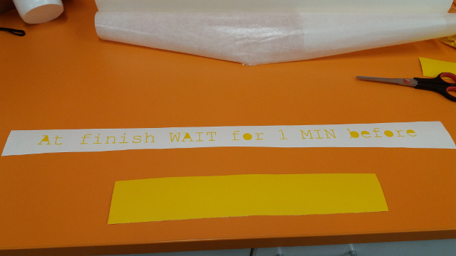
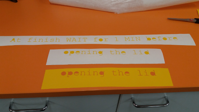
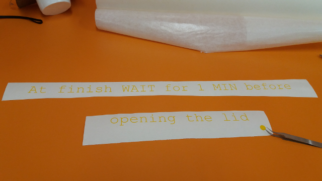
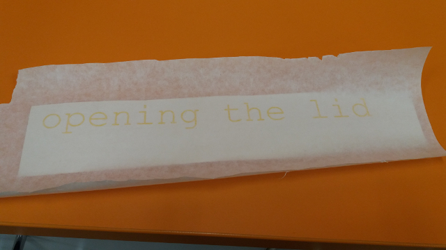
For the assignment, I've created a caution message to be placed on the laser cutting machine to instruct users to wait for 1 min before opening the lid after the job is finished. The image below shows the outcome of this assignment. Though, after observing people using the laser cutter, I can say that the caution message is not very effective: people are in a hurry to open the lid as soon as the machine's job ends. Probably a warning sign would add value to the text message or, even better, an audio message. Or perhaps the best solution would be locking the lid for 1 min.
The steps I took to create this label were:
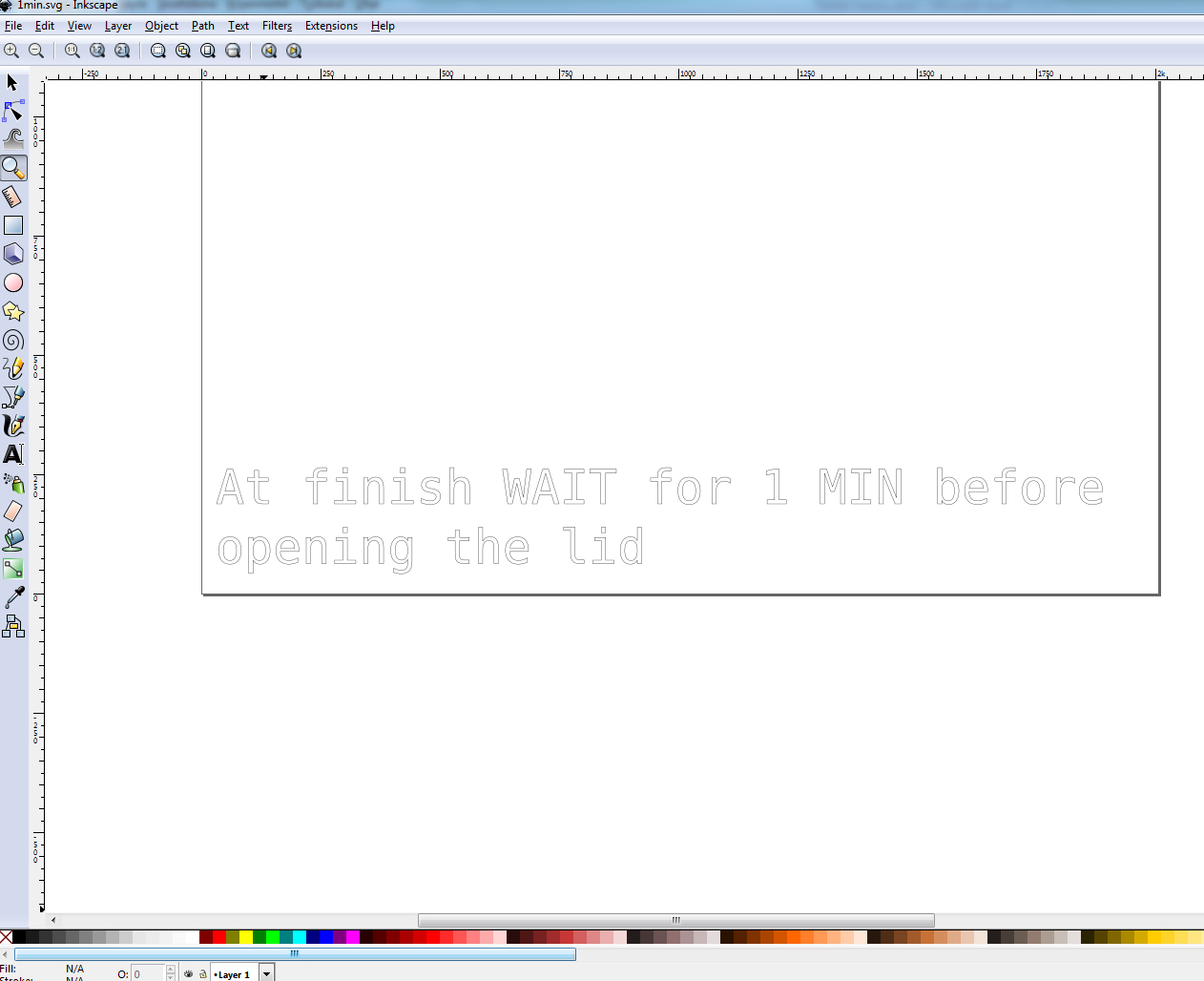
- Create in Inkscape the model to be vinyl cut (Create and edit text objects, Menu Text > Text and font... > Font: Monospace; Size 80)
- For optimal use of vinyl material when printing, the model should be placed in the lower-left corner of the page. See picture below. Otherwise, the settings of the vinyl cutter should be adjusted accordingly. To adjust the settings of the vinyl cutter, press Origin, move the down arrow until Edge is selected, then press ENTER. Then hold on Origin button until you see Origin set.
- The model (i.e., the text) should have the following Fill and stroke properties: No fill; Stroke paint: any color (e.g., black [0 0 0 255]); Stroke style: Dashes: continuous, Width: 0.500 pt
- Set the document dimensions (Menu File > Document Properties > Width 566 mm; Height: 1600 mm). These dimensions were adjusted after checking the printing properties for cutting area.
- Save the document as .svg file
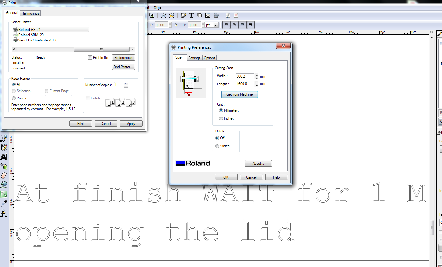
- Print the document (File > Print...):
- Use the vinyl cutter as printer (Select printer: "Roland GS-24")
- Set the preferences for the cutting area (Preferences > Size - Cutting Area > Get from Machine --> Size: Width 566,2 mm; Length 1600 mm)
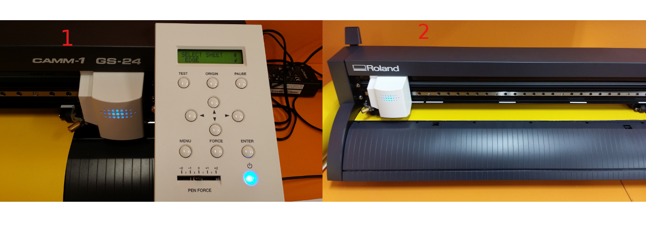
The operation of the vinyl cutter: 1) insert the vinyl sheet and align it to the edge when lever is down; put the lever up when the vinyl is alinged. 2) On the console use up and down arrows to select EDGE and press Enter button. 3) Set origin (use arrows to adjust cut origin; press origin until Origin Set)
See below some intermediate steps in the vinyl cutting assignment.
As a sumary of my work in GIMP, the following tools and commands were very useful to edit the images for this webpage:
- Image > Crop to selection (it crops the unselected areas)
- File > Create > From Clipboard (it creates a new file wiht contents from Clipboad, e.g., after PrintScreen command)
- File > Export as ... > write File name and type > Set Quality to 100 (to achive very high quality of the image)
- Layer > Scale layer (to adjust the size of a layer)
- Edit > Paste as > New layer
In Inkscape, View > Display mode > Outline is useful for displaying thin lines.
Summary of Tools used
Software
Inkscape - to create the models for vinyl and laser cutting
Inkscape laserbox - a plug-in for Inkscape to design boxes to be laser cut (press-fit kit)
GIMP - to edit images for documenting the process
Hardware
Laser cutting machine Epilog Laser Fusion - for cutting 2D parts and engraving
Vinyl cutting machine Roland GS-24 - for cutting vinyl and making labels
Source files for download
Lasercut-box extension files
Inkscape files for Box6 laser cutting and vinyl


