Study archive - Week 7
Computer-controlled machining
The lecture 7 on Wednesday 9.3 was about computer-controlled machining, also called CNC machining (which stands for Computer Numerical Control). With CNC machining, a computer program converts the design produced by Computer Aided Design software (CAD), into numbers. The generated numbers represent the coordinates of a graph structured in the so-called G-code that the machine can understand. The g-code is read by a computer which controls the movement of the machine (e.g., milling machine, cutter, router) along the x, y, and z coordinates resulting in cutting and shaping of the material. (see also this introduction to CNC)
The process/program that converts the design into g-code is called CAM (computer-aided manufacuring).
Besides coordinates, the g-code also program the feed rates and speeds. Different materials can be used such as wood, metal, and plastic.
The task of the week is to make something BIG. The idea is to use materials of size or form for which laser cutting is not suitable/efficient. I decided to make a wood carrier to be used in Fablab Oulu for recycling the plywood used with the laser cutter (the most popular machine in our lab).
Set up
In our lab, we have an in-house made CNC machine that uses Mach3 SW.
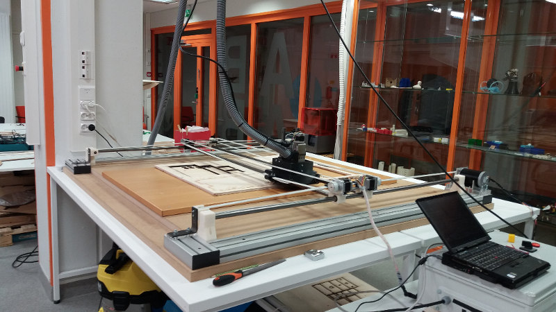
The machine is not very fast, but works fine with moderate speed and feed rate. The bit for this task is of type flat with 6 mm diameter.
The material is plywood of 9 mm and 6 mm.
CAD model
I have used Autodesk Inventor Professional for the design because it provides free student license and it has CAM extension SW (HSM Express).
I have looked for different examples of boxes and wood carriers and I selected a couple based on which I made my design.
One model is referenced as Plywood CNC Box by phidauex and shared under Creative Commons 2.0 license. Taken this as a basis, I have adapted it using other models that have one handle on top of the box.
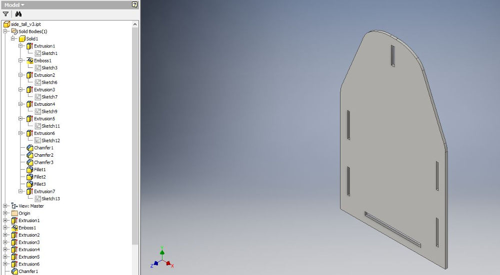
When I knew how the final object will look like, I have created 4 parts in Autodesk Inventor Professional: 1) bottom and 2) handle (the thickness of these was set to 9 mm), 3) short side and 4) tall side (with thickness 6 mm).
The basic process for creating these parts consists of sketch and extrusion. At some parts I have also used fillet, emboss, and chamfer (see the pictures below).
Bottom part (478 x 328 x 9 mm)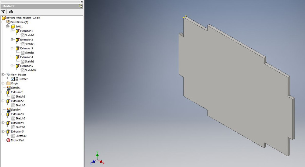
After this part was milled and assembled in the final product, I realized that two of the extrusions (on the long sides) were not needed. Thus for a future replication the width could be scalled down to 288 mm. This could have been forseen if I would have assembled the parts in Autodesk Inventor.
Handle part (450 x 100 x 9 mm)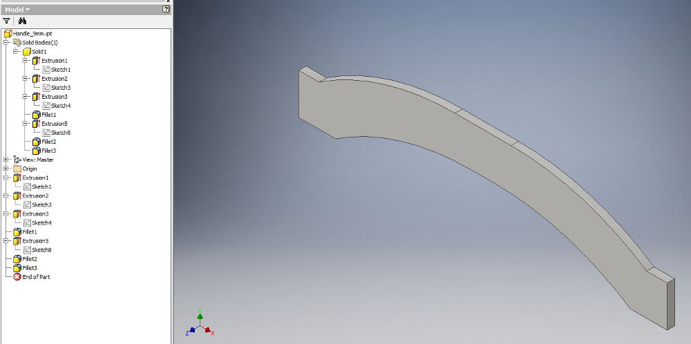
This part was desgined a bit short; however it holds quite well in the assembly (if replicated, the length should be 478 mm).
Short-side part (478 x 235 x 6 mm)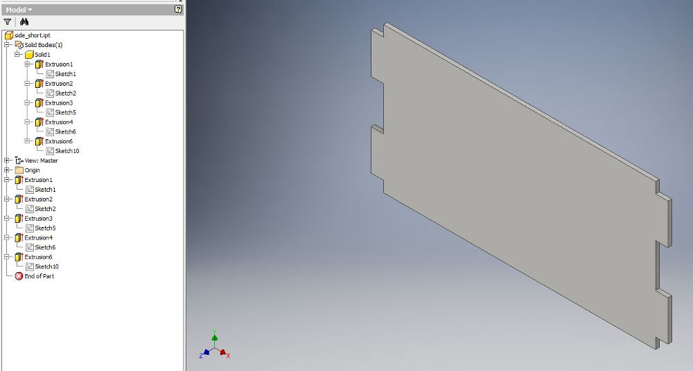 Tall-side part (500 x 300 x 6 mm)
CAM
The conversion of the design parts in g-code was done with the CAM utility in Autodesk Inventor Professional. This was installed by installing the free HSM Express software for Autodesk Inventor. The download starts with registering here.
The steps are: 1) setup the parameters for coordinates, origin, stock (Job > Setup); 2) setup the parameters for milling, e.g., 2D contour, Slot, etc. (2D Milling > 2D Contour; Slot), and 3) simulate the milling process and save generate the g-code (Toolpath > Simulate; Post Process)
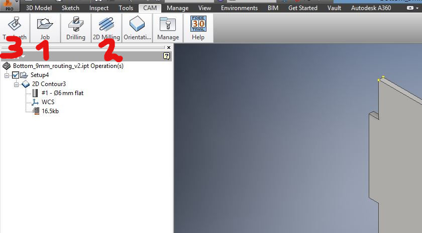
Below I illustrate the CAM process for the tallside part; the same approach was used for the other parts except that it was used only one step, 2D Contour.
Job setupFirst, I have setup the coordinates, the origin, and the model.
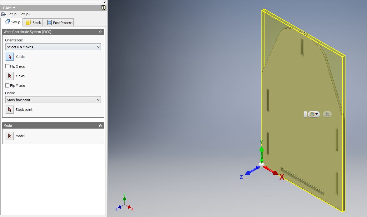
The coordinates are selected by pressing the buttons in the left-panel and then clicking on the model in the main window (x is the horizontal axis and y is the vertical axis; z should have the arrow pointed upwards). The origin has to be set on the upper part of the model.
Second, I have set up the dimensions of the stock.
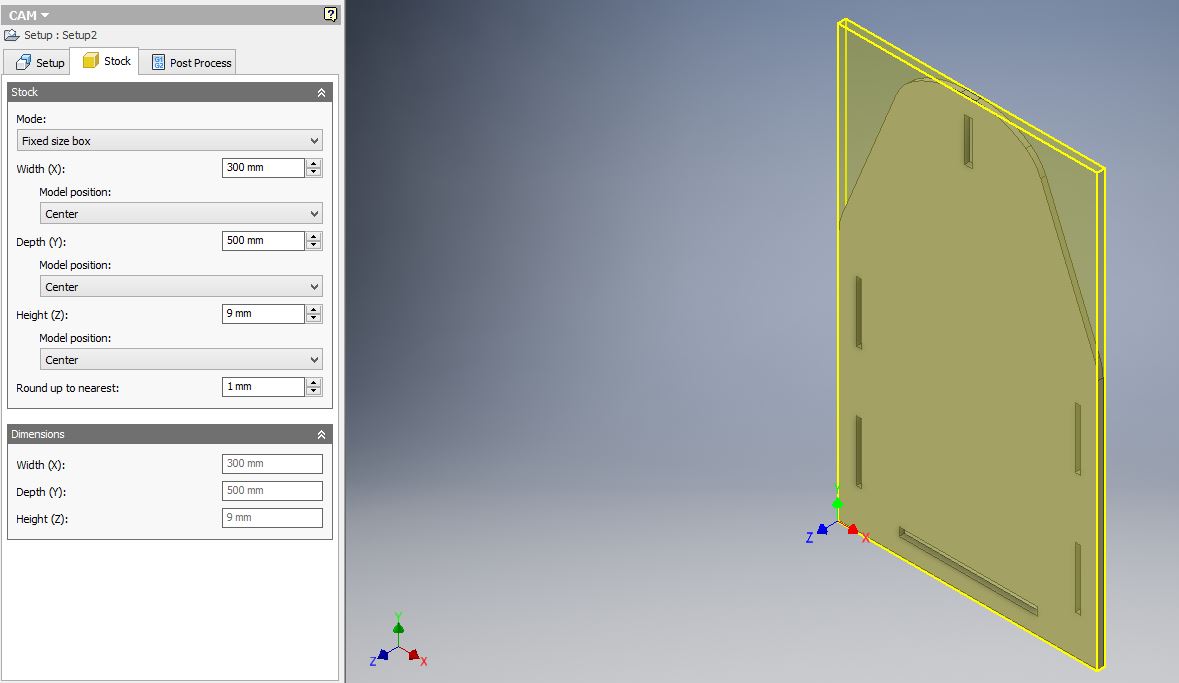
During the actual machining, the height (z) created some problems because the surface on which the stock was placed was not flat or the machine itself has the axes not perfectly straight - sagging slightly in the middle (thus the 9 mm height was not uniform and some parts were not milled through). This problem was solved during milling by manually adding into the g-code lines to redo some extra milling at specified z positions.
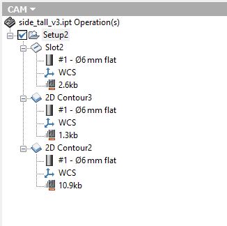
2D Milling setupThree milling steps are defined: slots for the lateral and upper slots; 2D contour for the lower slot; another 2D contour for the outer contour.
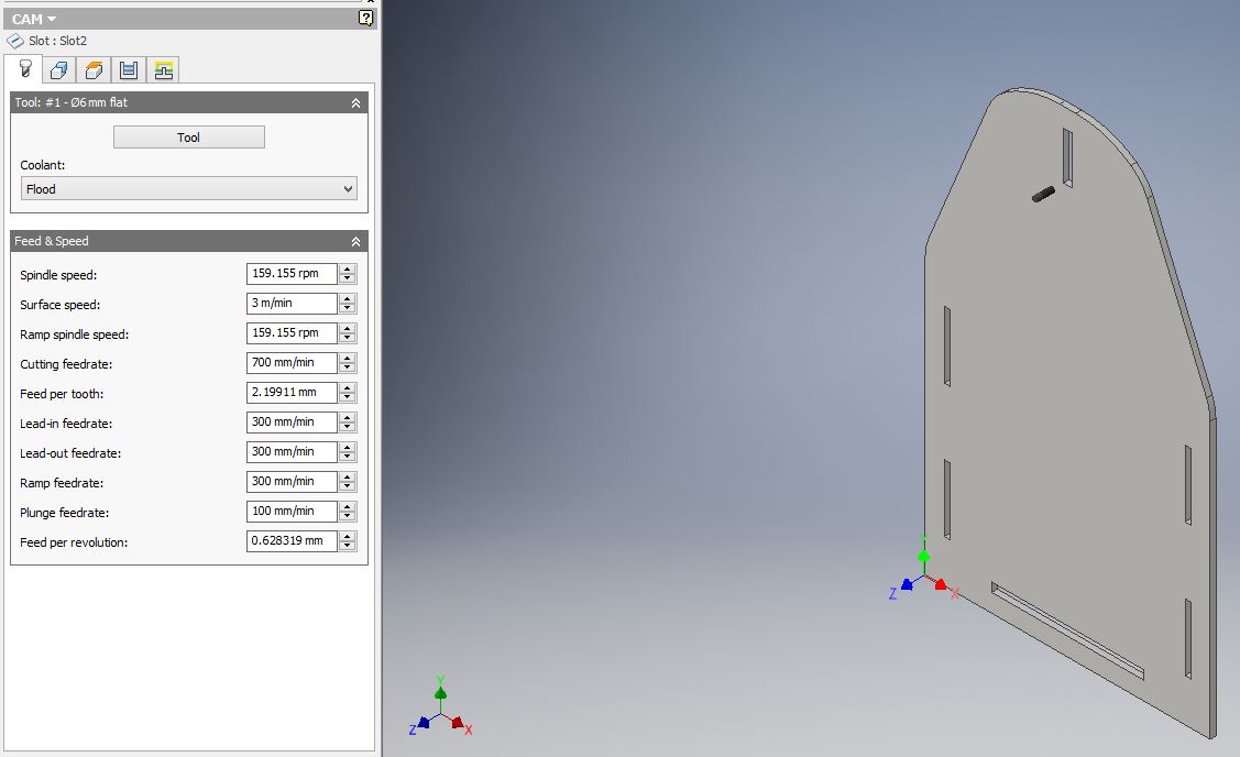
For each of the steps, I have selected the tool and defined the feed and speed rates. These are the same for all tasks:
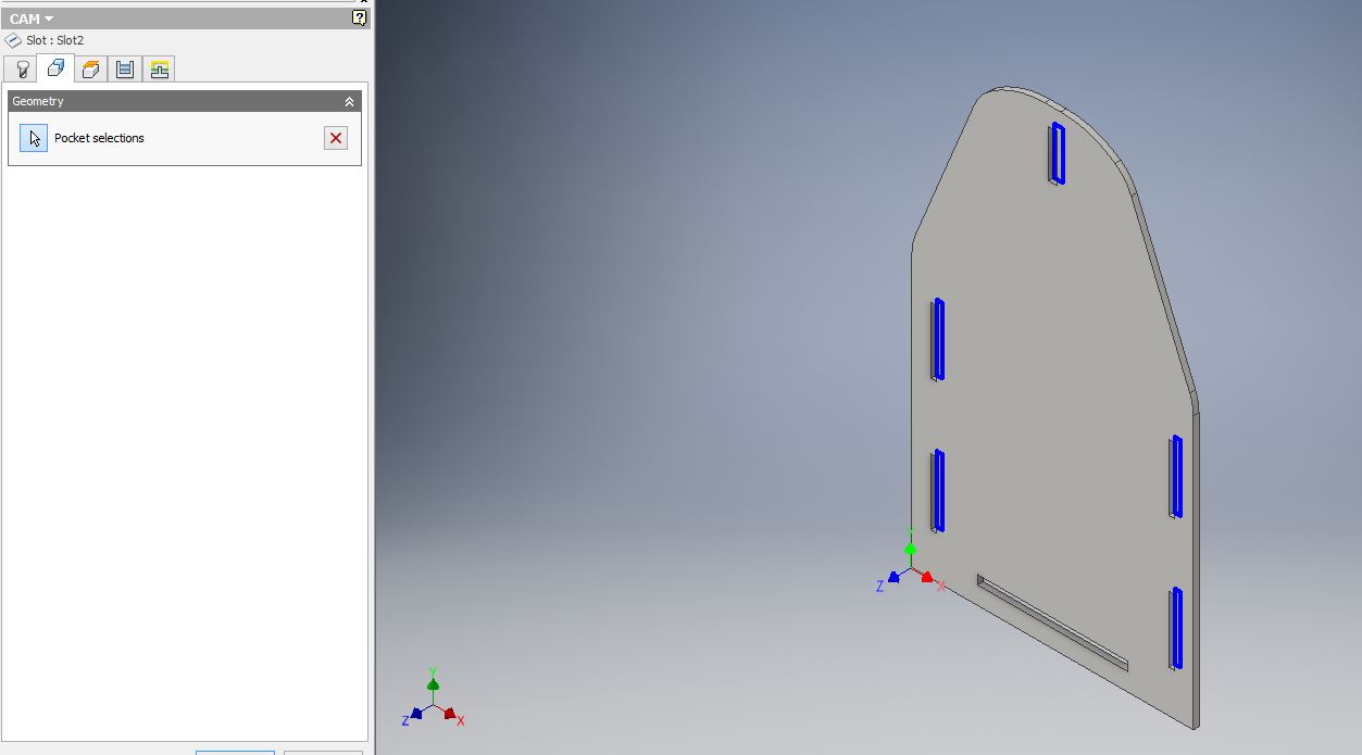
For each of the tasks, I have selected the geometry.
For the slots, I selected the pockets:
For the 2D contours, I selected the contour and the tabs for the outer contours:
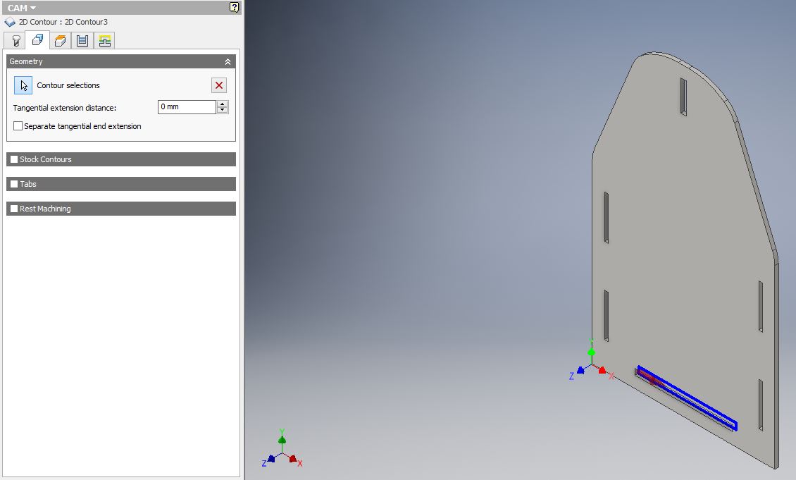
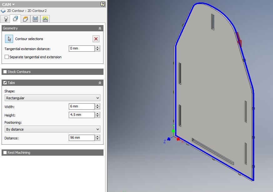
The tabs ensure that the milled part is secured on the stock and does not detach/moves away during milling. It is dangerous if it moves during milling. The tabs can be sawn away after the job is complete.
The heights parameters were set as default.
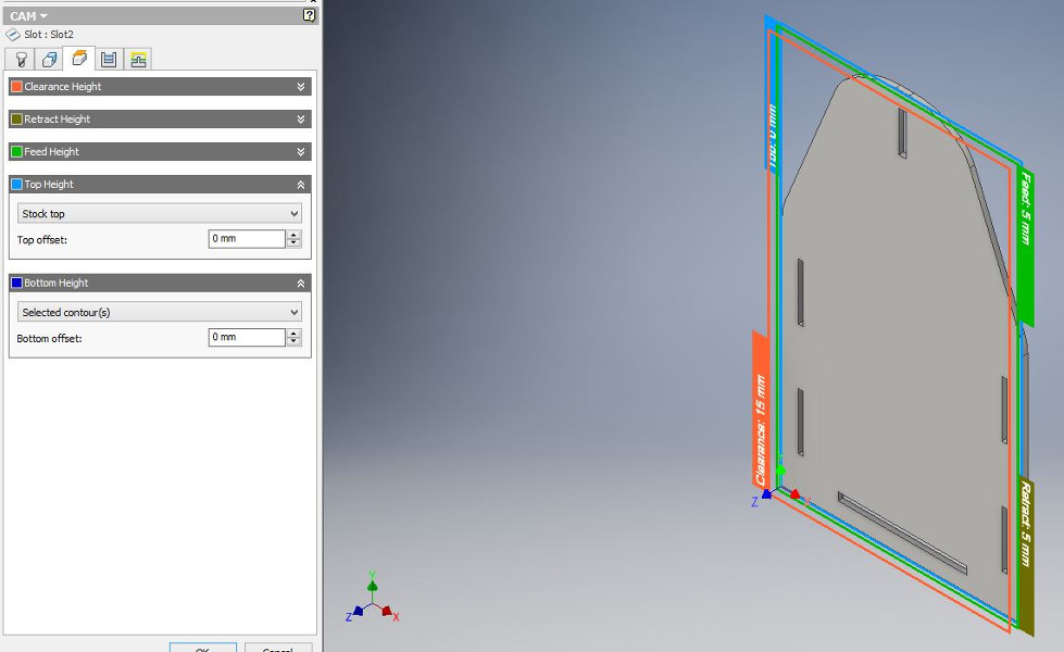
Despite the fact that I set the stock in some parts as higher than the thickness of the plywood (i.e., 9 mm instead of 6 mm) to ensure that all 6 mm plywood will be milled through, this did not happen. The g-code only generated paths to z -7.5 instead of -9. This was because the Bottom height was set to selected contours; I had to manually rewrite the g-code to remill some parts of the plywood that were not cut through. However, towards the end of the milling process, when I understood better the dynamics of this process, I set the Bottom height to Stock bottom and the g-code was successfully created.
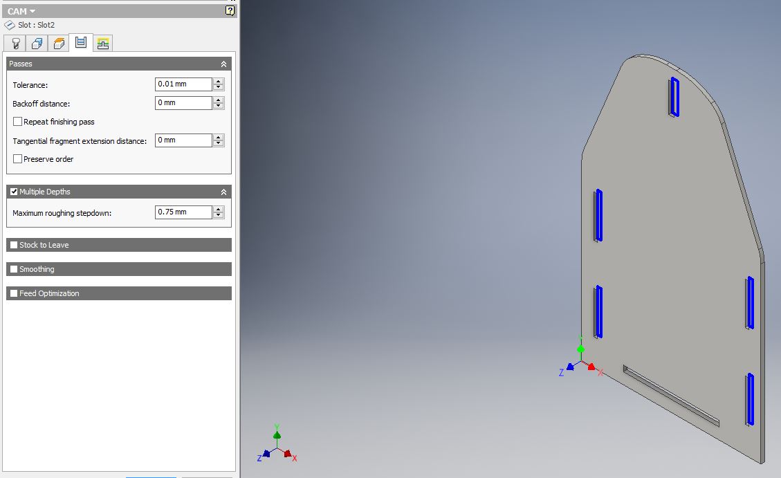
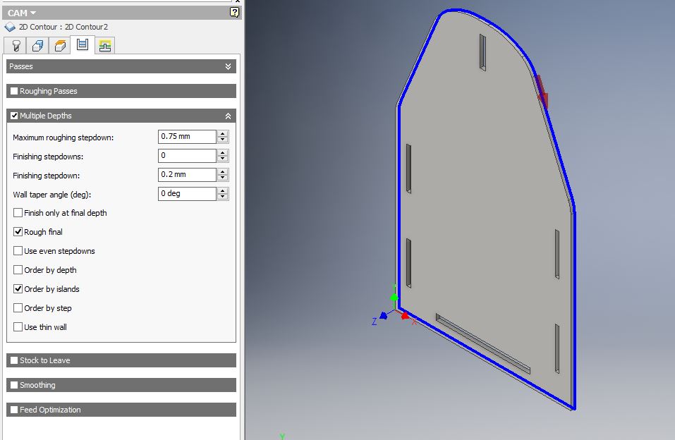
Next, I set up the passes, namely the multiple depths stepdown.
Finally, the linking parameters are defined.
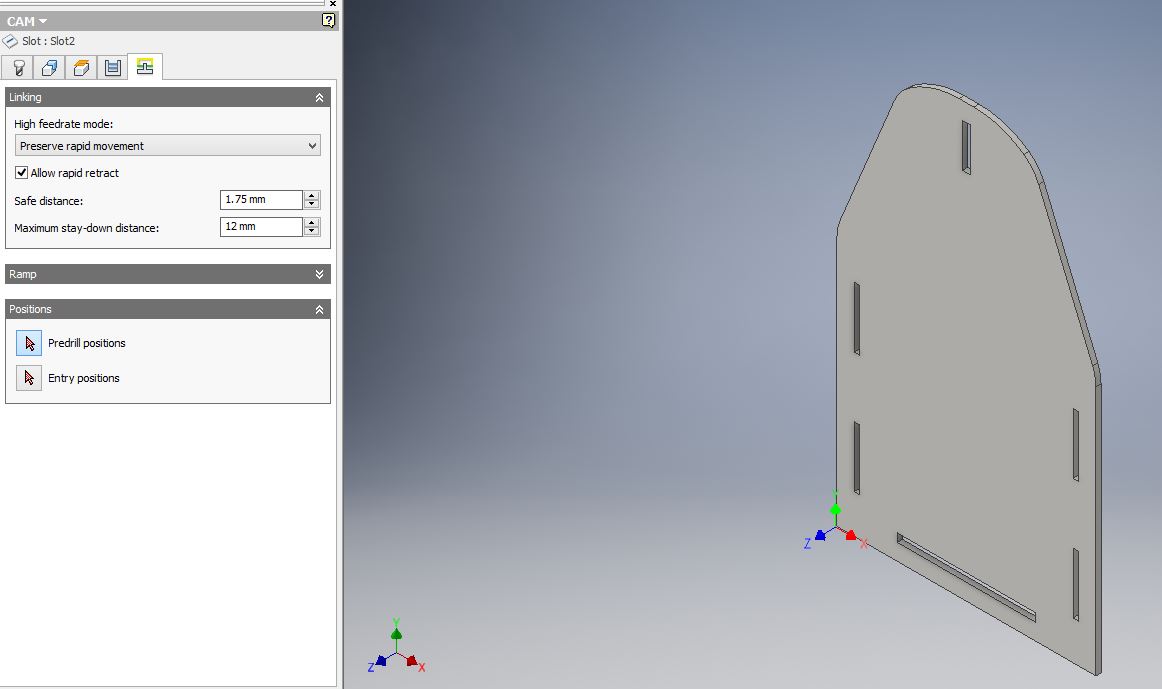
For the slots, the paramters were set as default.
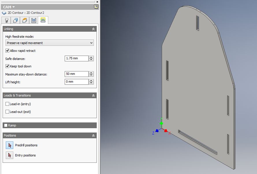
For 2D contours, the leads and transitions (lead-in and lead-out were deactivated).
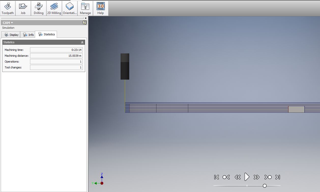
ToolpathFor inspecting that the milling will go well, simulate the process: Toolpath > Simulate. You can also see there how long it takes the milling.
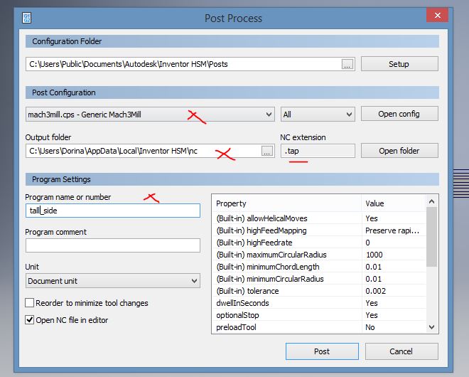
The last step is to generate the g-code: Toolpath > Postprocess. Select the mach3 and add name to the file.
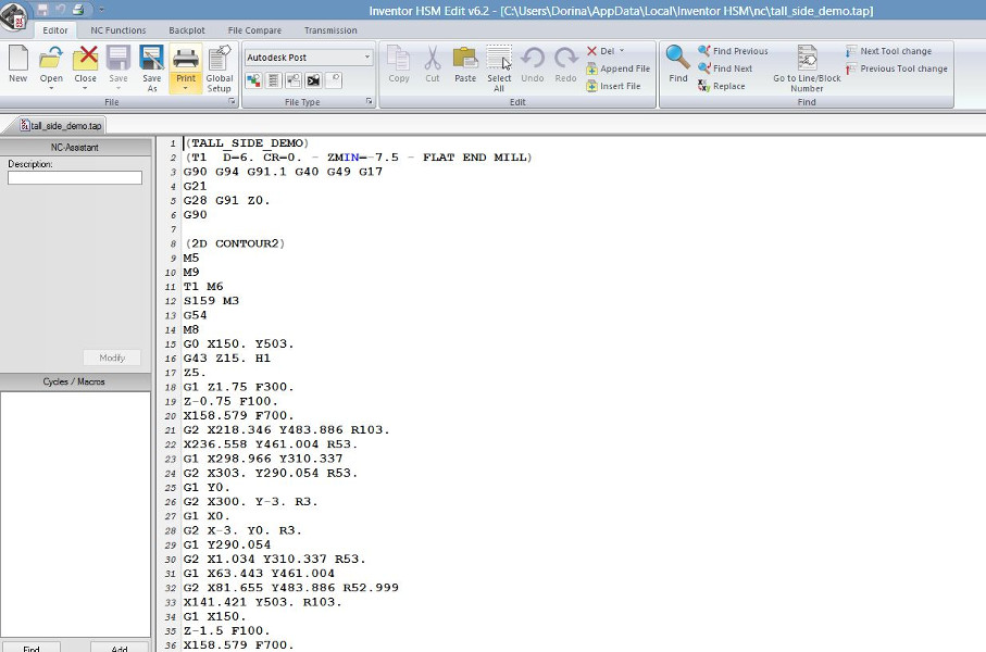
The g-code can be edited in a text editor such as Notepad.
In my case, in all generated files I have removed the line G28 G91 Z0 at the beginning of te file (this was to prevent the bit to go to the origin Z0); I have added Z5 to after M8 (so to make sure the bit will be high enough and does not touch the plywood when moving); and removed the lines at the end of the file G28 G91 Z0 and G28 X0. Y0. (again to prevent the bit to go to the origin points and eventually scratch the stock).
CNC machining
The first thing is to attach the plywood to the board by using screws.
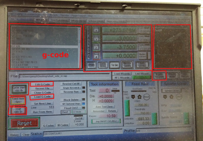
At this step, the g-code files (.tap) were loaded into the Mach3 application. The CNC machine is powered using a switch button. First operation is to set the origin points for x, y. Then is important to test in the air the g-code (by setting z origin somewhere above the stock). If everything is fine, set the z origin correctly (preferably by selecting an x,y location where the stock is at the highest level). To make sure the origins are set correctly press the REF ALL HOME button, zero again the x,y, and x, and check that the machine coordinates are also 0.
Press Regenerate toolpath to make sure the paths are correct in the right-hand side panel.
Switch to the maximum the spindle button on the cnc machine console.
Press Cycle Start to start the cutting/milling. (Press Space to pause the process, if necessary.)
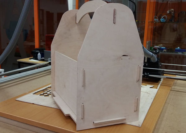
Some pictures during the milling and assembling processes are presented below.
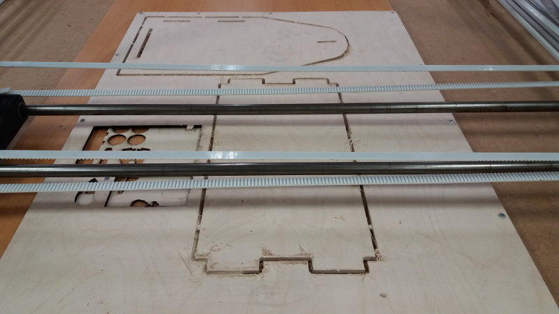
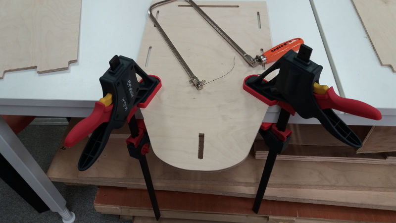
After milling, the parts are sanded and sawn.
The final object: a carrier for recylcing the plywood pieces after laser cutting.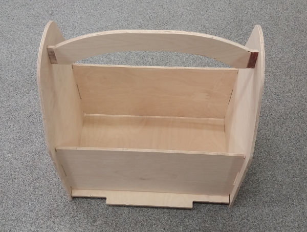
Summary of the week
- The cutting air test is important to ensure there are no problems with the setup. I have learned the workflow and benefits of CNC machining. The cutting precision is important to obtain parts that are as close as possible with the designed models, especially if joints are to be used. I have not used fixings like glue or screws, but I had to sand out and saw the extra material.
- Autodesk Inventor Professional is a good SW for CAD and CAM (with the HSM Express).
Summary of Tools used
Software
Autodesk Inventor Professional - for design of 3D parts
HSM Express for Autodesk - for CAM (creating the machining files)
Mach3 - for running the g-code and CNC machining
Hardware
CNC machine - in-house made at Fablab Oulu
Several tools - for sawing, sanding
Source files for download
Autodesk CAD files (.ipt)
HSM Express CAM files (.tap)


