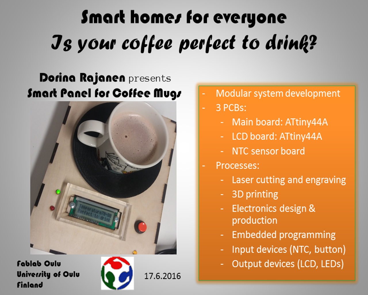
Final project: Smart home panel for coffee mugs
This page describes in detail the project execution. A shorter, concised version of the project development process is on Week19 page.
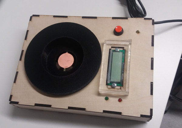
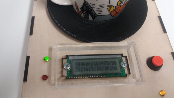
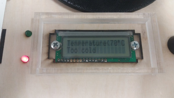
The final project refers to a system that measures the temperature in a coffee mug. The main components of the system are a control panel with button, leds and LCD and a mugh holder that has a temperature sensor. The temperature is displayed on an LCD screen by providing an estimate (too hot - higher than 80 degrees C; too cold - lower than 70 C; and perfect to drink - temperature between 70-80C). This information is also shown on LEDs: green led is on when temperature is perfect; red led is on when temperature is too low or too high. Another LED is also on when the system is powered up. The system is powered up using an FTDI cable connected to a computer.
1. Time management and task completed
The planned schedule was managed so that the following tasks were completed by the deadlines 17.6.2016 (project execution and presentation) and 1.7.2016 (weekly assignments revisions and project documentation).
- Week 20 (16. - 22.5) Define final project concept DONE; and REFINED (scalled down) during Week 23
- Week 21 (23. - 29.5) Make bill of materials and adjust final project concept based on availability of components DONE; and REFINED later (see below the final BOM)
- Week 22 (30.5 - 5.6) (1) Design and fabricate the physical interface: the control panel case and the mug holder
- Week 23 (6. - 12.6) Work on electronics production including networking and HCI programming DONE, but SKIPPED networking and GUI; focused on LCD programming
- Week 24 (13. - 17.6) Finalize the final project, documentation, and presentation. Aim is to present on 17.6. DONE the following: finalizing the physical interface, temperature NTC programming in C, the presentations slide and video; live presentation on 17.6. Documentation postponed for after project presentation.
- Week 25 (20.6 - 1.7) Revise weekly assignments (CNC, output devices, networking) DONE; also Final project documentation was included here.
DONE; and REFINED in Week 24
(2) Start the electronics design and production
DONE
2. System features and components, BOM, and Fab processes
Basic features- activate/deactivate system (using the FTDI power cable connected to the computer)
- measure temperature in coffee mug
- send data (temperature) to control panel
- display temperature on LCD and LEDs
- control the LEDs with button on the control panel
- physical user interface (control panel): button, leds, LCD, mug holder integrated in a functional prototype
- mug holder (3d printing)
- temperature sensor for coffee mug
- control panel (plywood laser cutter and milling and acrylic components)
- LCD
- LEDs
- on/off buttons for activate/deactivate LEDs
- power source (5V via FTDI cable connected to computer)
- computer
| Material/component | Source | Total Cost |
|---|---|---|
| ABS-M30 for the 3D printing | Fablab Oulu | n.a. |
| Support material for the 3D printing | Fablab Oulu | n.a. |
| NTC thermistor | Fablab Oulu | 2.98 USD |
| Microcontroller ATTiny 44A (x 2) | Fablab Oulu | 3 USD |
| LEDs (x 3) | Fablab Oulu/SparkFun | 2 USD |
| FTDI cable | Fablab Oulu | 16 £ (21.5 USD) |
| LCD | Fablab Oulu | 8.38 USD |
| Button | Fablab Oulu | 1.95 USD |
| Other electronic components (resistors, capacitors, crystal resonators, pin headers, etc.) | Fablab Oulu | about 10 USD |
| Wires | Fablab Oulu | about 2 USD |
| Nuts and bolts | Fablab Oulu | about 1 USD |
| Plywood 4mm | Fablab Oulu | about 10 USD |
| PCB | Fablab Oulu | about 3 USD |
| Acrylic 4mm | Fablab Oulu | n.a. |
| Total | -rounded- | about 65 USD |
| Part made in Fablab | Process used |
|---|---|
| 1. Mug holder with slot for electronics | 3D design and 3D printing |
| 2. Electronic board for LCD and control panel | Electronics design, production, and embedded programming |
| 3. Electronic board for temperature sensor | Electronics design, production |
| 4. Electronic board for temperature sensor and control panel programming | Electronics design, production, and embedded programming |
| 5. Plywood case for control panel | 2D design and laser cutting |
| 6. Acrylic protective screens (x 2) for LCD and electronics | 2D design and laser cutting |
3. Detailed project execution
LCD board production
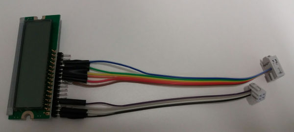
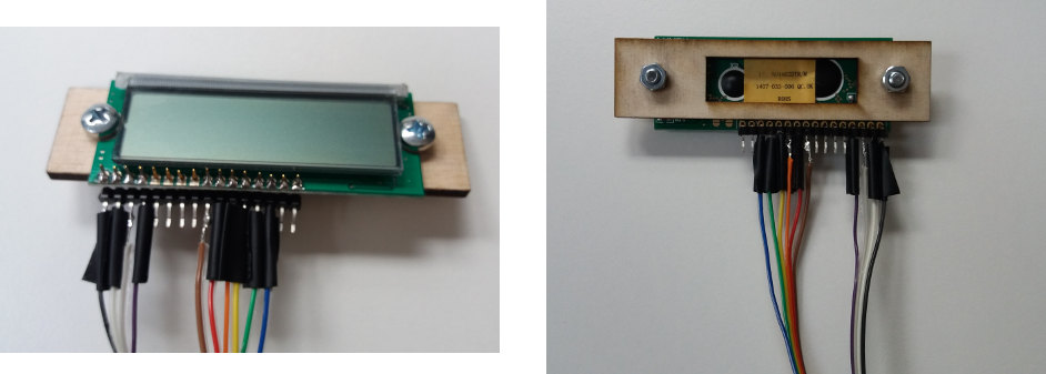
The LCD board was produced for the Output devices assignment. The detailed process of designing and making the board is described in Week13 page. The LCD is connected to an LCD module, LCM-S01602DTR/M.
For connecting the board to the LCD module, I have added an LCD connector which I adapted from a FTDI connector type with 16 pins (by bending the yellow pins). The yellow pins are connected to the LCD and the silver pins to the wires to be connected to the ATtiny44A. Soldering the wires to the pins was quite difficult.
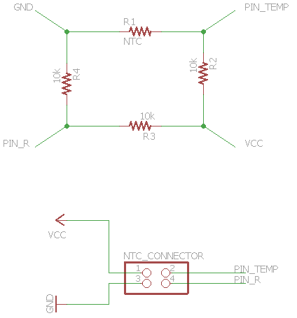
NTC board production
NTC board is a small board that is designed to fit in the mug holder. It has only 5 components: NTC thermistor, 3 resistors of 10K each, and a 2x2 pin header for power, GND, resistance values.
The schematic and board layout.
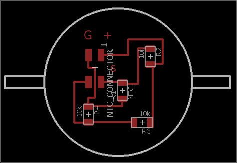
The traces and outline.

The milled and cleaned board.
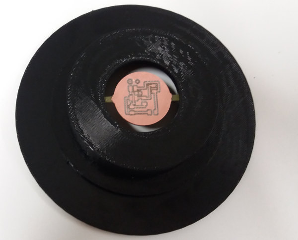
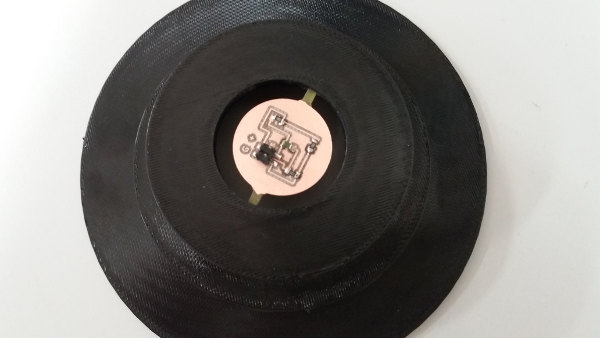
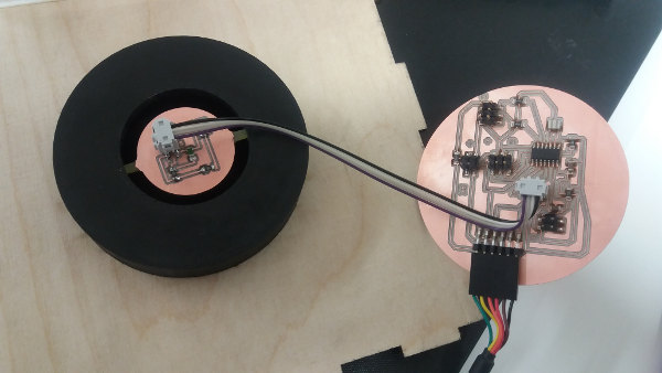
The board fitted in the mug holder.
The board soldered.
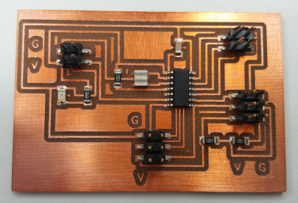
Main board production
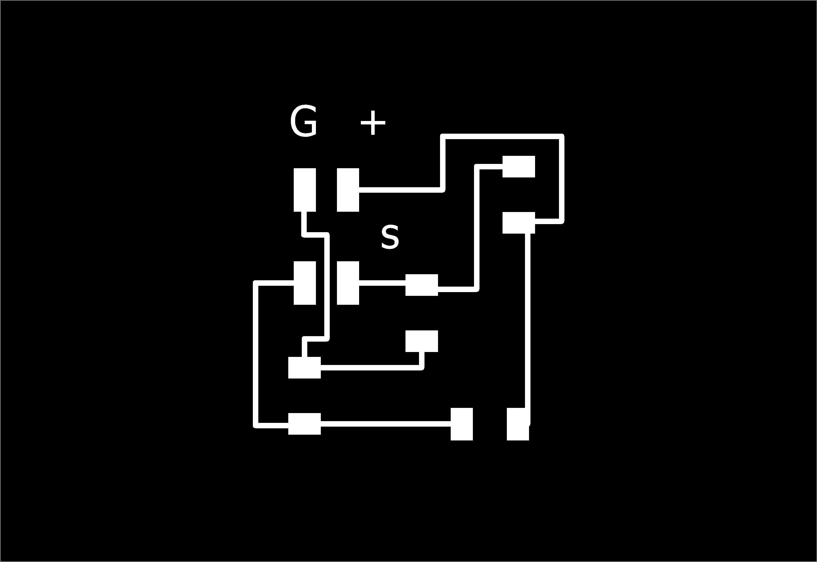
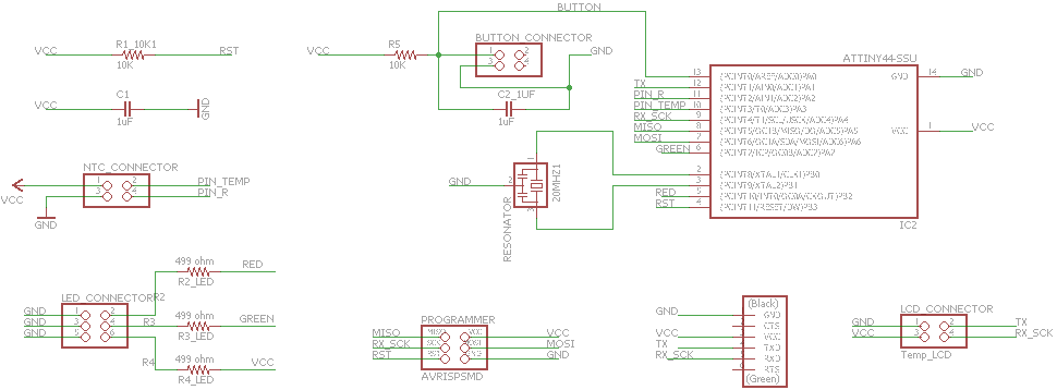
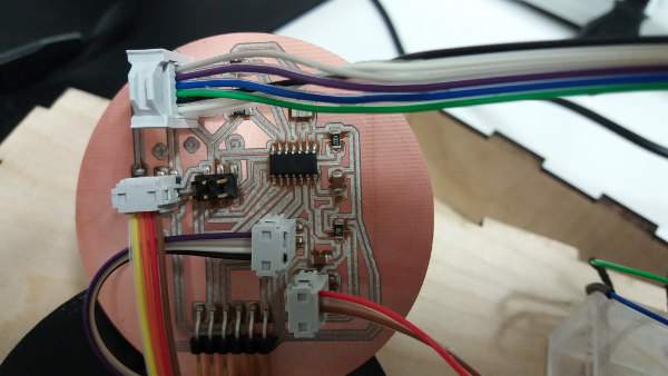
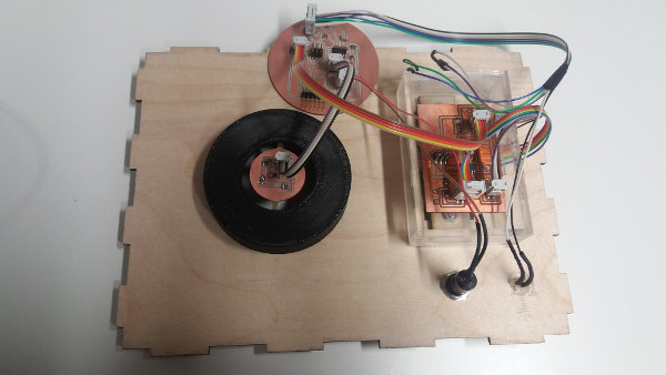
The main board is central to the system because it connects all other boards and control panel components together. It has an FTDI pin header to connect to computer for power and to provide serial communication capabilities to the system. It connects to the NTC board via a 4-wire cable and to the LCD board via 2 cables, 4-wired (power and GND) and 6-wired (data bus). It also has pin headers for connecting the leds and button on the control panel. The microcontroller is ATTiny44A.
The schematic and board layout.
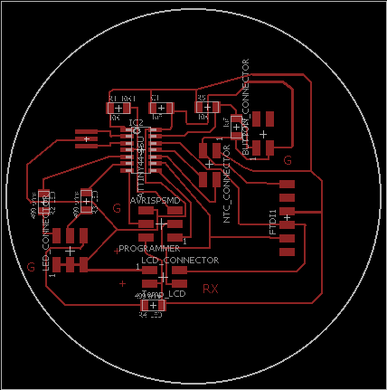
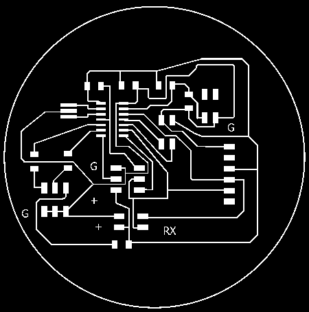
The traces and outline.

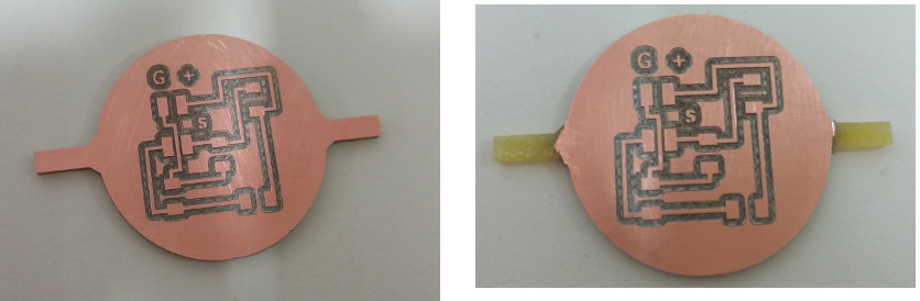
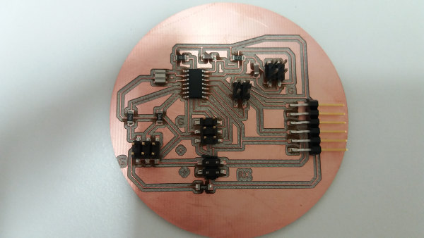
The board soldered.
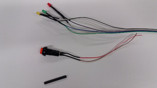
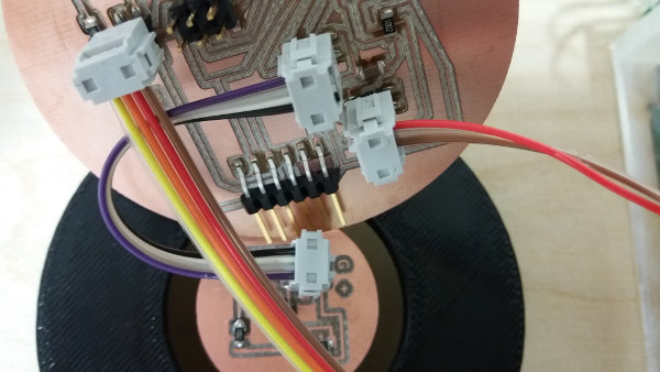
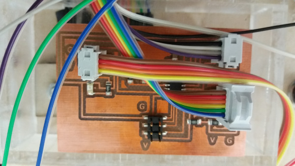
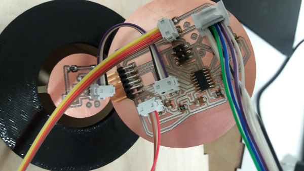
Wiring and connecting the electronics
I have prepared cables and wires for connecting the electronic parts together before programming. The following pictures show how the wires are prepared and connected.
Programming
For programming, I have used as starting points the following codes by Neil available at Fab Academy lectures on output devices (hello.LCD.44.c), embedded programming (hello.ftdi.44.echo.c), and input devices (hello.temp.45.c; hello.temp.45.py).
Two programs are created: 1) main_board.c for recording data from ntc sensor; and for controlling the button and leds for displaying the sensor data. 2) LCD_board.c for reading the temperature data from microcontroller and transmitting it to the LCD module for displaying on the screen.
LCD board programming
The code for the LCD programming reads data from microcontroller and displays it on the LCD. The data in microcontroller is received via serial communication from the main board.
First the code initializes the LCD module. At this step, I have contributed by removing the cursor and blinking.
 /// display on, cursor off, blinking off
	 lcd_putcmd(0);
	 lcd_putcmd(DB7+DB6);
The temperature data is received in Rx pin using the function get_char(). The main loop initializes the LCD pins and moves the cursor to the zero position. 4 frames are read from the microcontroller Rx pin (PA7) and after this the low and high values of temperature volatge data are read (measure_low and measure_high). These are converted into an integer.
///See License in the file////

	...
	/// I have defined two variables for the low and high bytes
		 static char measure_low;
		 static char measure_high;
    ///--- GETTING THE FRAMES first---///

		 while (1) {   //open while2
		//framing code based on hello.temp.45.py
			 byte1 = byte2;
			 byte2 = byte3;
			 byte3 = byte4;
			 get_char(&serial_pins, serial_pin_in, &byte4);
			 if ((byte1 == 1) & (byte2 == 2) & (byte3 == 3) & (byte4 == 4))
			 break;
		 }           //closes while2

		 get_char(&serial_pins, serial_pin_in, &measure_low);
		 char_delay();
		 get_char(&serial_pins, serial_pin_in, &measure_high);
		 char_delay();
 //CONVERTING measure INTO int
	    int measure_int = 0;
		 measure_int = 256*measure_high + measure_low;  ///converting the sensor data into integer to be displayed
The current value of the integer representing the temperature measured in V is used to write a message in the flash memory and to display it on the LCD.
///See License in the file////
        ...
// print first line from flash
	static const char line1[] PROGMEM = "Temperature";
    lcd_putstring((PGM_P) line1);
  ///displaying the temperature (rough estimation, not accurate calibration)
   		 if ((measure_int > 480) & (measure_int < 512)){  //open main if
			 lcd_putchar('>');
			 lcd_putchar('8');
			 lcd_putchar('0');
			 lcd_putchar(223);  /*symbol for degree*/
			 lcd_putchar('C');
			 // move to second line
			 //
			 lcd_putcmd(DB7+DB6);
			 lcd_putcmd(0);
			 static const char line2[] PROGMEM = "Too hot";
			 lcd_putstring((PGM_P) line2);
		 }  //closes main if
		 else if (measure_int > 511) {    //open else and if2
				  lcd_putchar('<');
				  lcd_putchar('7');
				  lcd_putchar('0');
				  lcd_putchar(223);  /*symbol for degree*/
				  lcd_putchar('C');
				  // move to second line
				  //
				  lcd_putcmd(DB7+DB6);
				  lcd_putcmd(0);
				  static const char line2[] PROGMEM = "Too cold";
				  lcd_putstring((PGM_P) line2);
			 }   //closes if2
		 else {
			  lcd_putchar('7');
			  lcd_putchar('0');
			  lcd_putchar('-');
			  lcd_putchar('8');
			  lcd_putchar('0');
			  lcd_putchar(223);  /*symbol for degree*/
			  lcd_putchar('C');
			  // move to second line
			  //
			  lcd_putcmd(DB7+DB6);
			  lcd_putcmd(0);
			  static const char line2[] PROGMEM = "Perfect to drink";
			  lcd_putstring((PGM_P) line2);
		....
Main board programming
The code for the main board writes data from the temperature sensor and controls the leds according to the temperature based on button press.
I initialized the A/D conversion for the Attiny44A using information from the microcontroller datasheet. Then I initialized the led pins as output pins and button pin as input pin. For programming the button and leds so to activate the leds when button is pressed once and deactivate them when button is pressed a second time, I defined two variables status_button and status_leds to hold values ON (or 1) for button when pressed at times 1, 3, 5, ... and OFF (or 0) when button was not pressed (initial status, or pressed at times 2, 4, etc.); similarly the status_led is OFF when led are off and ON when led is on.
///See License in the file////
...
	static char chr_l;
	static char chr_h;
	int temp_value;
	char status_button;
	char status_leds;
...
	// initialize output pins
	//
	set(serial_port, serial_pin_out);
	output(serial_direction, serial_pin_out);
	//
	// init A/D
	// updated for attiny44A
	ADMUX = (0 << REFS1) | (0 << REFS0) // VCC ref
	| (0 << ADLAR) // right adjust
	| (0 << MUX5) | (1 << MUX4) | (0 << MUX3) | (0 << MUX2) | (0 << MUX1) | (1 << MUX0); // 20(PA2-PA3)
	ADCSRA = (1 << ADEN) // enable
	| (1 << ADPS2) | (1 << ADPS1) | (1 << ADPS0); // prescaler /128  (divided by 128)
	ADCSRB = (1 << BIN)   // bipolar mode
	| (0 << ADLAR); //setting 0 (default) the adlar in ADCSRB register to make right adjust of result
	//

	//initialization of pins as output (for leds: Pa7 green, and PB2 red)
	DDRA |= (1 << PA7); //green led pin initialized as output
 	DDRB |= (1 << PB2); //red led pin initialized as output

	//initialization of button pin as input
	DDRA &= ~ (1 << PA0); //button pin initialized as input

	status_button = 0; //no button press
	status_leds = 0; //leds off
The main loop starts with sending 4 frames so that to achieve synchronization between sensor data and microcontroller. Then it initiates and completes the A/D conversion resulting the high and low ADC values.
The low and high ADC values are combined into temp_value which represents an integer from 0 to 1023 and can be converted into temperature (e.g., degrees Celsius). I have used the temp_value to estimate roughly a threshold when temperature is too high or too low.
        ///See License in the file////
        ...
        temp_value = chr_h*256 + chr_l;

		//sending data to leds

		//initially button is not pressed; (PINA & (1 << PA0))
		//when pressed, (PINA & ~(1 << PA0)))

		//next commands are for "leds = on" when activated by button press; when button released remembers the last status of leds (i.e., leds stay on when button is released)
		//when pressed second, leds = off (leds stay off until a next button press)
		//code works fine:
		if (PINA & (1 << PA0)) {   //button is not pressed   //open main if
			status_button = 0;
			if ((status_button == 0) & (status_leds == 0)) {  //open if2
				PORTA &= ~(1 << PA7); //GREEN LED IS OFF
				PORTB &= ~(1 << PB2); //RED LED IS OFF
			} //close if2
			else {  //open else2 (alternative to if2)
				if ((status_button == 0) & (status_leds == 1)) { //open if3 (inside else2)
					status_leds = 1;
					if (temp_value > 480) {   //open if4
						PORTA &= ~(1 << PA7); //GREEN LED IS OFF
						PORTB |= (1 << PB2); //RED LED IS ON
					}                           // closes if4
					else {   //open else4
						PORTA |= (1 << PA7); //GREEN LED IS ON
						PORTB &= ~(1 << PB2); //RED LED IS OFF
					}       // closes else4
				}                                                   // closes if3
			}      // closes else2
		}                                                   //closes main if
		else {       //open main else
			if (status_leds == 0) {  //open if5
				status_leds = 1;
				if (temp_value > 480) {  //  open if6  //480 is selected as a threshold (adjust for your taste)
					PORTA &= ~(1 << PA7); //GREEN LED IS OFF
					PORTB |= (1 << PB2); //RED LED IS ON
					}                    //closes if6
					else {  //open else6 (alternative to if6)
					PORTA |= (1 << PA7); //GREEN LED IS ON
					PORTB &= ~(1 << PB2); //RED LED IS OFF
					}       //closes else6
			}                       //closes if5
			else {   //open else5 (alterntative to if5)
				status_leds = 0;
				PORTA &= ~(1 << PA7); //GREEN LED IS OFF
				PORTB &= ~(1 << PB2); //RED LED IS OFF
			}       //closes else5
		}          //closes main else

	}  // closed while
}  //closed main
Control panel design and fabrication
I used Inkscape and Lasercut-box plug in to design and make a plywood case for the control panel. The plug can be downloaded from https://github.com/Neon22/inkscape-LasercutBox
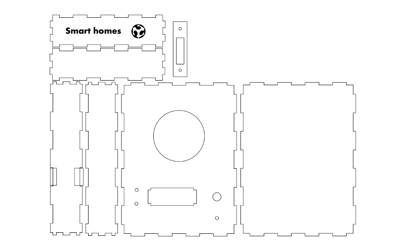
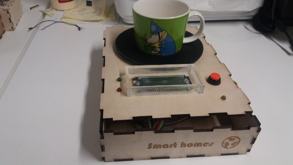
The box is also decorated with text and Fab Academy logo. The box has slots for mug holder, leds, button and LCD case. On one long side there are slots for the cable and for opening the case. The box is not glued, but it is press fit. The small rectangle with slots and holes is for fixing the LCD module in place.
I have also designed and made two acrylic protective screens for protecting the LCD module and wires.
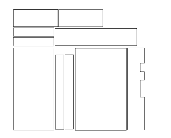
These parts are glued together resulting in two screens which are then glued on the plywood cas; one on the front side protecting the LCD screen and pins and the other in the inside on the box, protecting the LCD module and wires.
Mug holder design and fabrication
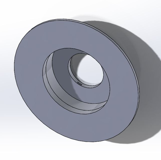
I designed and 3D printed a mug holder in Solid Works. The assembly is formed of 2 parts (Part 1 and plate). A third part was also designed to simulate how NTC board fits the mug holder.
Part 1 is a mug holder of cylindric shape with two slots for the NTC board.
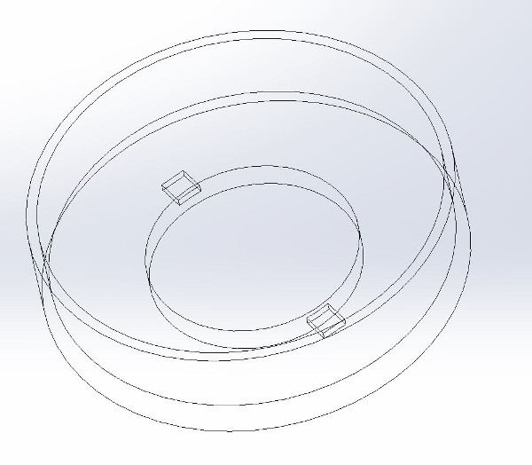
The NTC board dummy is fitted in Part 1 but is not 3D printed.
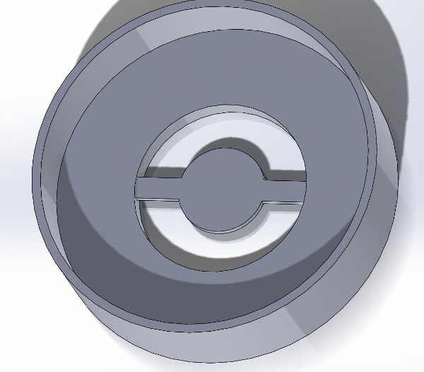
Part 2 (plate) of the mug holder is added to Part1 as if it would be a small coffee-cup plate.
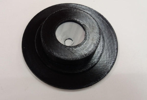
The 3D printed mug holder before disolving the support material.
4. Final project conclusions
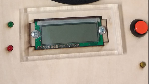
What has worked?Time management was successful. The final project was successful. The system measures the temperature in a mug placed on the mug holder. The temperature is displayed on the LCD screen by providing an estimate (too hot - higher than 80 degrees C; too cold - lower than 70 C; and perfect to drink - temperature between 70-80C). This information is also shown on LEDs: green led is on when temperature is perfect; red led is on when temperature is too low or too high. Another LED is also on when the system is powered up (connected to computer via FTDI cable). The system has also a pleasant and intuitive physical user-interface.
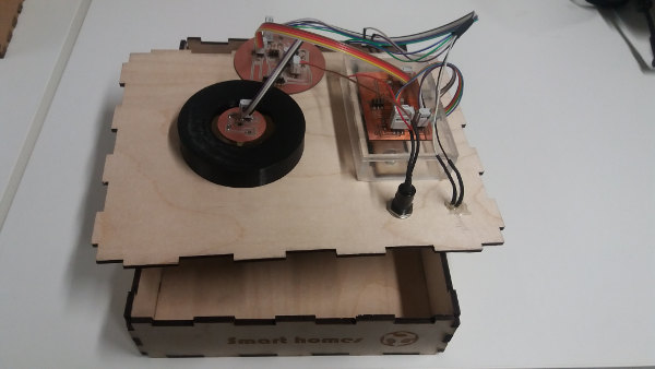
The system ready to use.
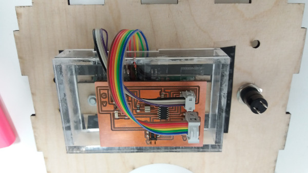
Electronics are inside the box.
The electronics are packed and connected for safety and proper functioning.
The system in use. Green led is on when coffee is perfect to drink. LCD dislays message and temperature estimate.
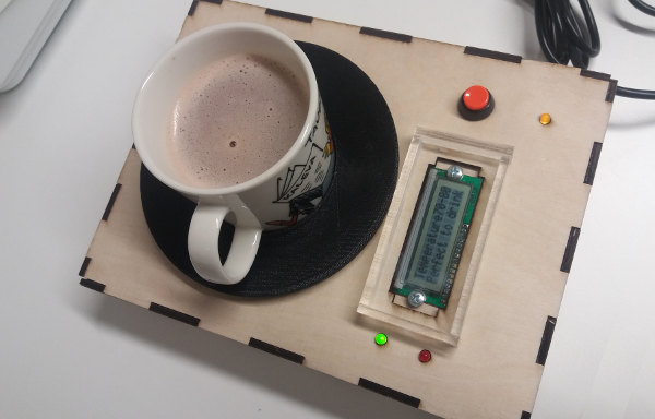
Yellow led shows that the system is powered on.
Red led is on when coffee is too cold or too hot. LCD dislays message and temperature estimate.
 What has not worked?
The final system does not display the exact temperature of the coffee because I did not find a way to convert the voltage into Celsius degrees in the code for the ATtiny microcontroller. I have tried with float number and math library, but without success. I will explore this later as a future development of the system.
What questions still need to be resolved?The final project is successfully completed. However, for future improvements I plan to find the way to convert the voltage in Celsius in the microcontroller code if it is possible for this type of microcontroller.
What have I learned?This project was interesting and challenging. I have learned the following:
- to manage time and project so to deliver a final prototype product by the deadline with good quality.
- to program microcontrollers with C language and read and use information from datasheets.
- to design and fabricate physical parts using Solid Works, Autodesk Inventor Professional, laser cutter and 3D printing machines, and putting these parts together to make a functional prototype.
- to apply licenses and copyright for own projects.
- to manage version control using git.
 Final presentation video
Deliverables
PCB design files (Eagle files): LCD.sch; NTC.sch; Main_Board.sch; LCD.brd; NTC.brd; Main_Board.brd
CAD files (Inkscape): plywoodcase.svg; acrylic_screens.svg
CAD files (Solid Works): Part1.SLDPRT; Part2.SLDPRT; plate.SLDPRT; mugholder.sldprt; mugholder.SLDASM;mugholder.stl
Code files (.c files): LCD board; Main board
License
This product was not created with the intention to commercialize it; it has been built mainly for learning the fabrication process. The product consists of Software, Hardware (design files), design features, and documentation. The Software (the main_board.c and LCD_board.c) is derived from MIT licensed and copyrighted code, therefore it preserves the original copyright holder and the MIT license. Thus the Software is free to use, change, distribute under MIT license conditions. Please refer to the MIT license for more details (described also on Week 18 page).
The non-software materials (design files, design features, and documentation) are distributed under Creative Commons Attribution 4.0 (CC BY 4.0), therefore anyone is free to use them, derive from them, distribute them under CC BY 4.0 conditions. See more details about license on Week 18 page.


