Project Robot Crab
It is necessary to decontaminate our rivers.

After first session, we had a meeting with our friends from Latin America and Beno (Peru) said that for the final project
we must propose something that has an impact on the community, which could be a social issue, environmental issue, among
others and leave our comfort zone with our proposals.
I got an idea that was hanging around my head for a while when I saw an exhibition called CULTIVOS by the artist Gilberto
Esparza, which shows a robot that feeds on contaminated water from rivers and then die when there is no more contaminated
water (Nomadic Plant).
My proposal consists in designing a robot that can navigate through the rivers and decontaminate the water that absorbs
and it could stop in the most polluted places and stick around, holding with his claws. I have called it "Robot Crab".

Schedule
I realize there is not much time for the project so I'm dividing the work into 2 parts:
- Mechanical, Electronic and Software Design
- Developing and Implementation of filters for decontamination
I propose this scheme:

BOM
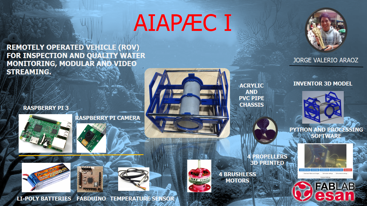
The short time and budget made it chooses to change the final project, I decided to build a ROV (Remote Operated Vehicle)
for monitoring water quality.
I designed a system block diagram:
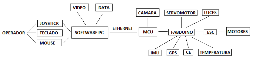
The list of components:
- (1) Raspberry Pi, version 2 or 3
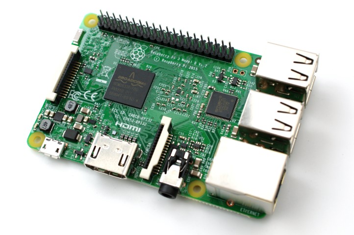
Link
- (1) Raspberry Pi Camera
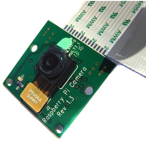
Link
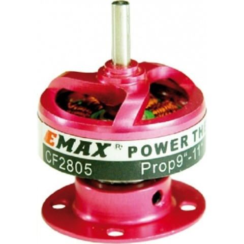
- (4) Brushless Motors
Link
- (4) Speed Controllers
Link
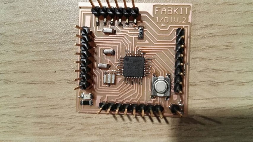
- (1) FabDuino
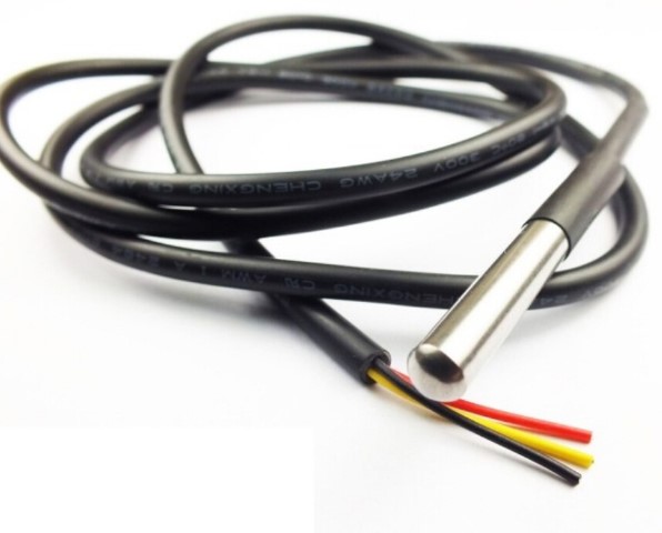
- (1) Waterproof DS18B20 Digital temperature sensor
Link
- (1) Battery Lipo 3S
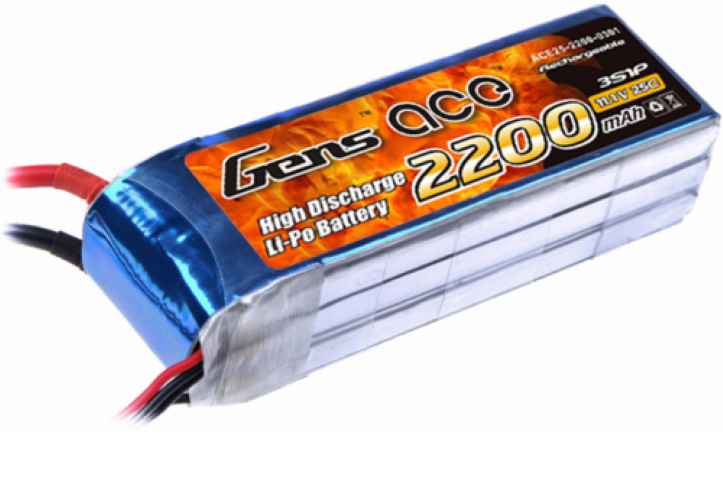
Link
- (1) Battery 4.8V NiMH
Link
- Acrylic thickness 6mm
- (1) Pipe PVC 4" x 30mm
- Nuts and bolts.
- Chrome bar 12mm and 1.5m
Mechanics
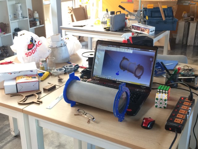
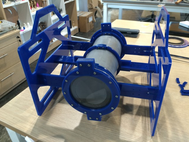
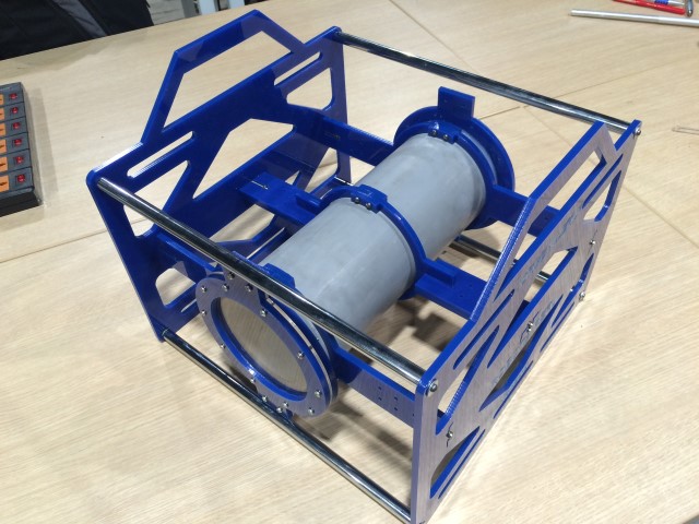
I used "Inventor" for 3D robot design. The main thing was to design the structure that supports the PVC pipe and the propellers.
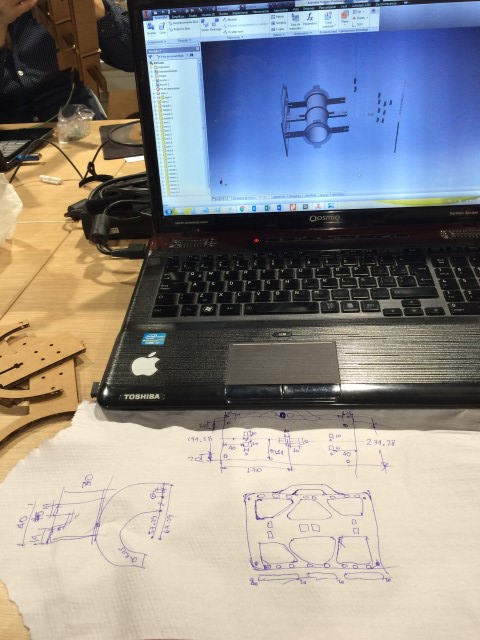
Final design
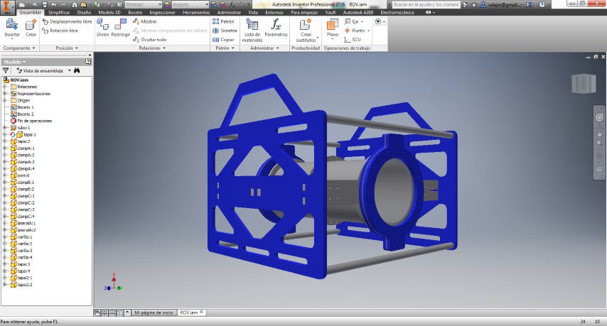
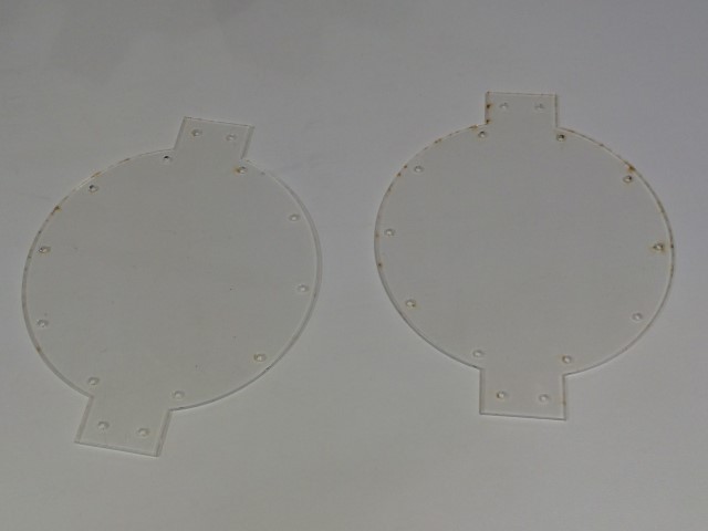
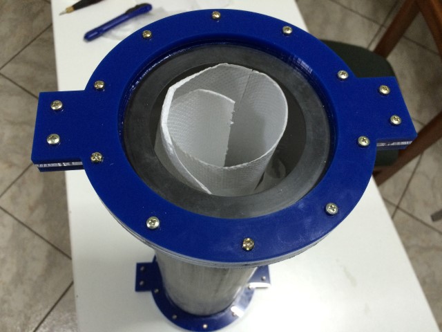
A critical detail is the design of the flanges to prevent the ingress of water PVC pipe, since all the electronics will be in it.
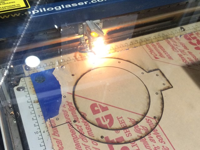
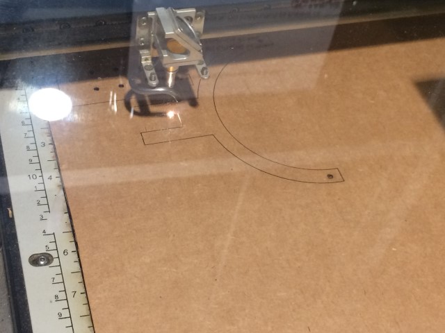
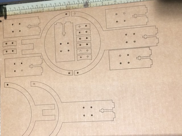
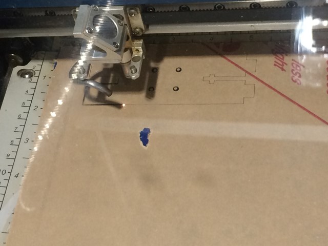
First I did some tests with cardboard to check tolerances in cutting.
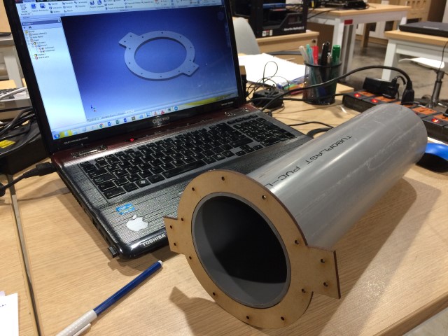
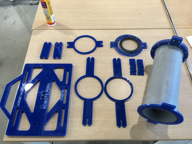
After testing the cuts made in acrylic.
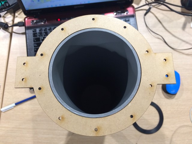
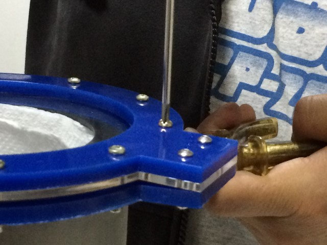
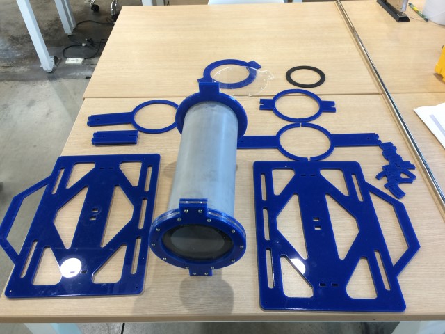
First I cut the flanges and caps which are then joined by screws and among them is a ring of rubber to prevent water ingress.
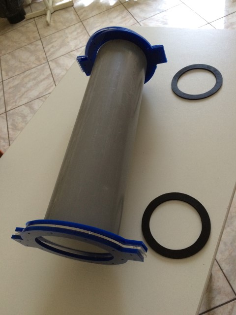
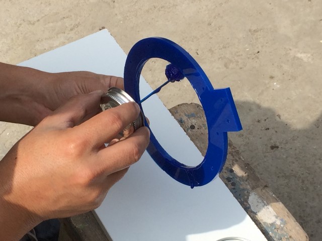
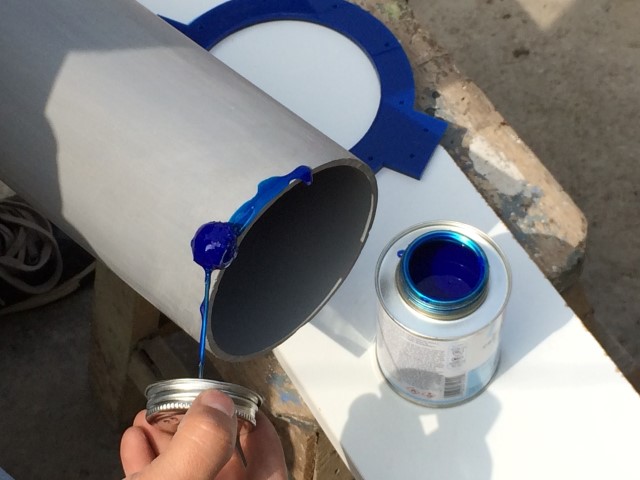
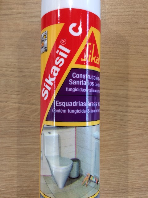
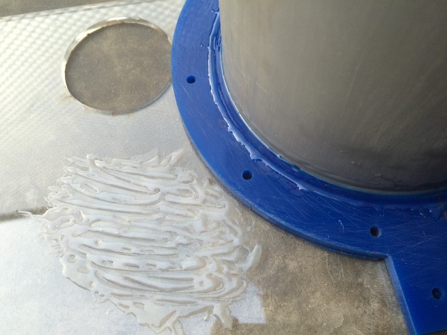
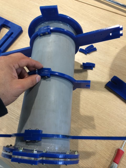
Another critical detail is to get the best glue for PVC and acrylic. First I used PVC cement.
the PVC cement smeared on the inner edge of the flange and the outside of the PVC tube.
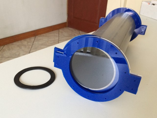
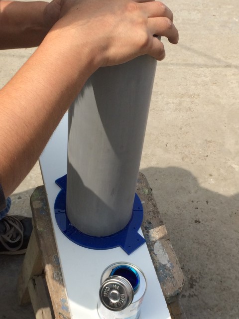
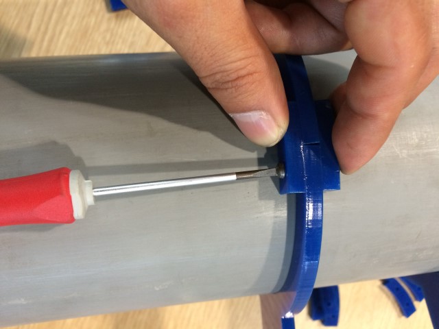
the pieces come together and let them dry for at least 6 hours.
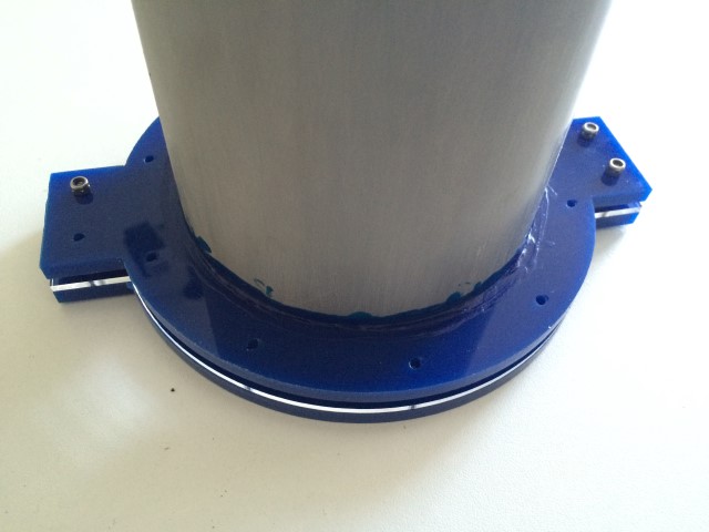
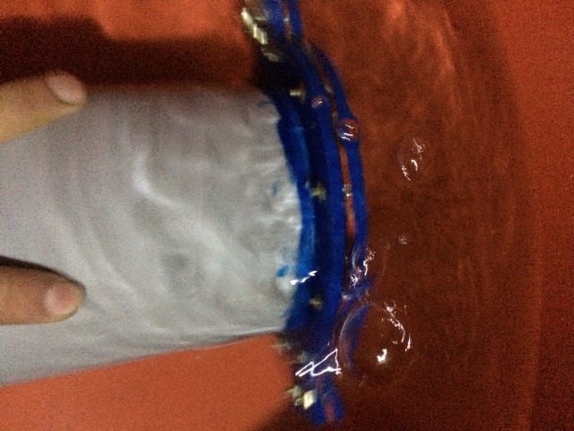
Place the rubber ring, the lid and the other flange and joined with screws. Ready for testing with water.
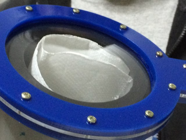
He failed the test, it looks like enters the water and bubbles.
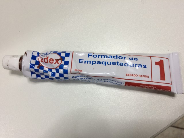
I tried forming packings and had the same result.
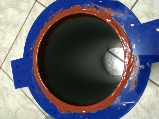
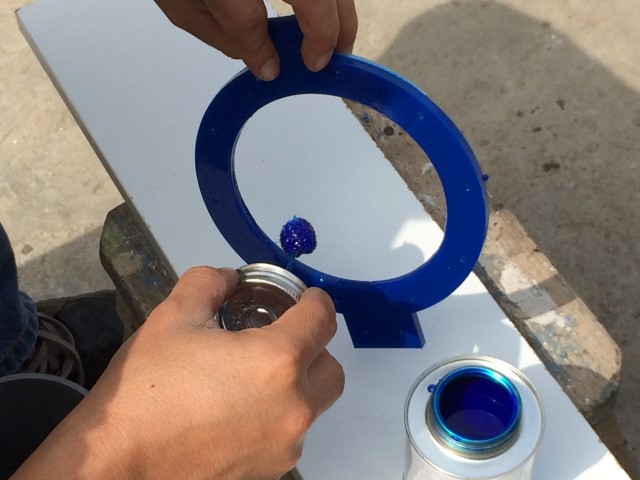
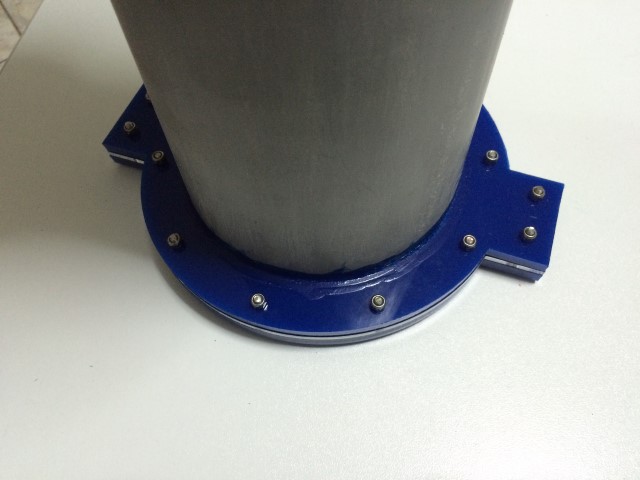
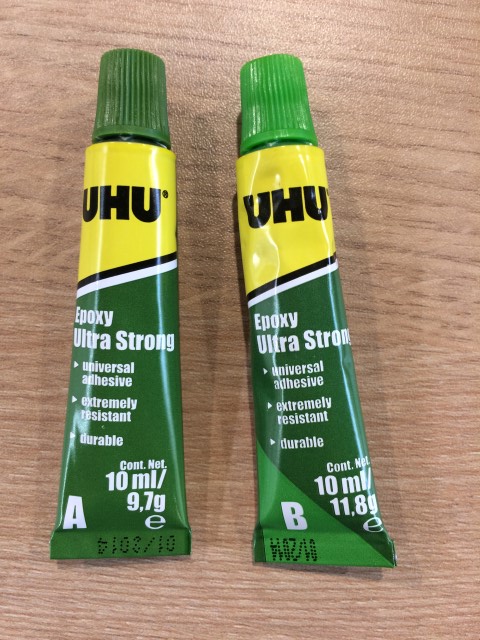
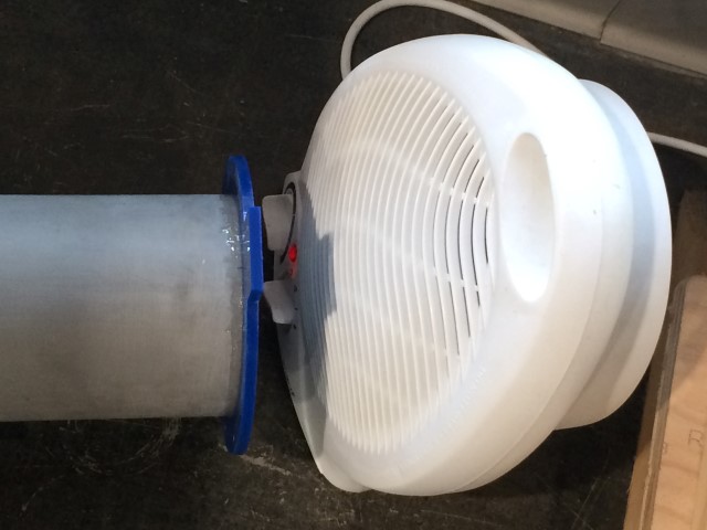
Finally I used epoxy glue and silicone to reinforce the outside.
I used a heater to accelerate the drying process.
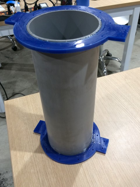
Flanges completed.
Then I proceeded to cut the rest of the structure, first used cardboard for testing.
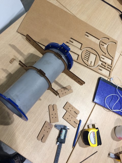
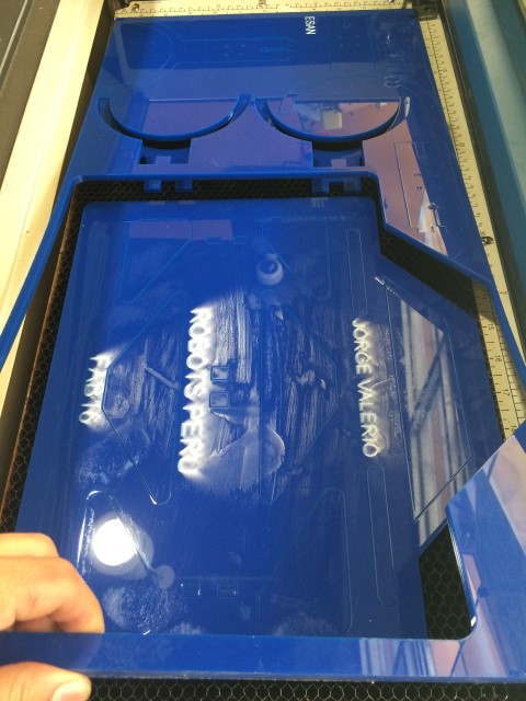
Finally acrylic.
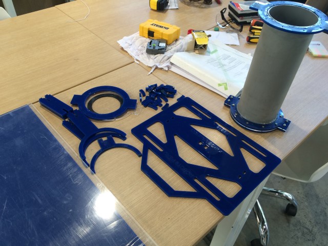
And put the pieces together with screws.
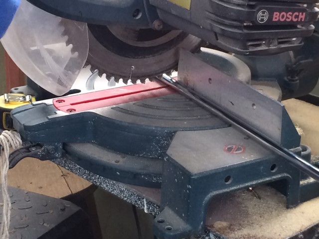
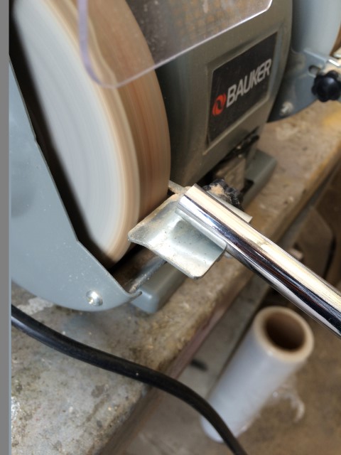
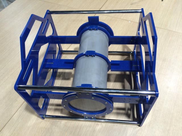
To reinforce the structure I used a chrome bar, 4 pieces of 30 cm were cut.
And filed down with an emery board.
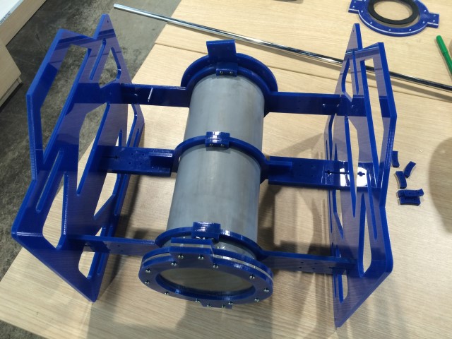
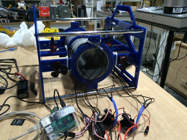
Finished structure.
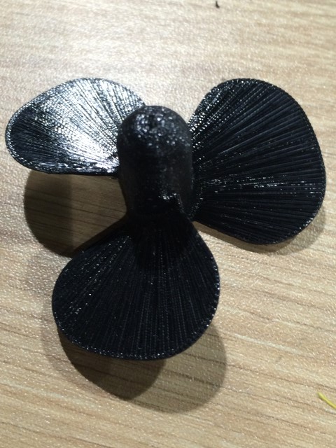
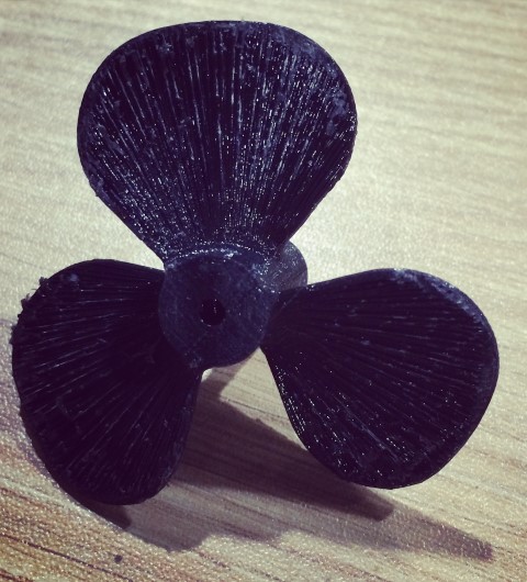
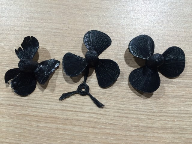
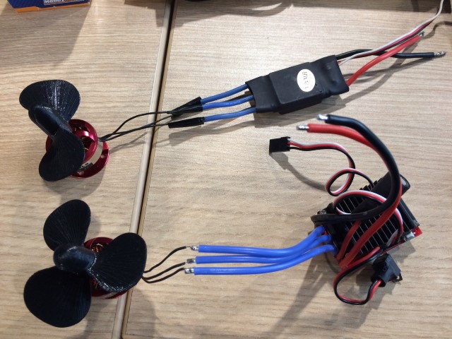
I also designed the propellers using Inventor. I designed a propeller with 3 blades and clockwise rotation, one propeller with 2 blades and propellers counterclockwise and 2 with 2 blades and clockwise rotation.
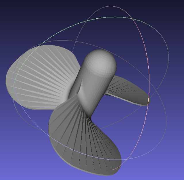
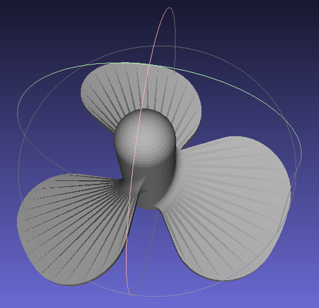
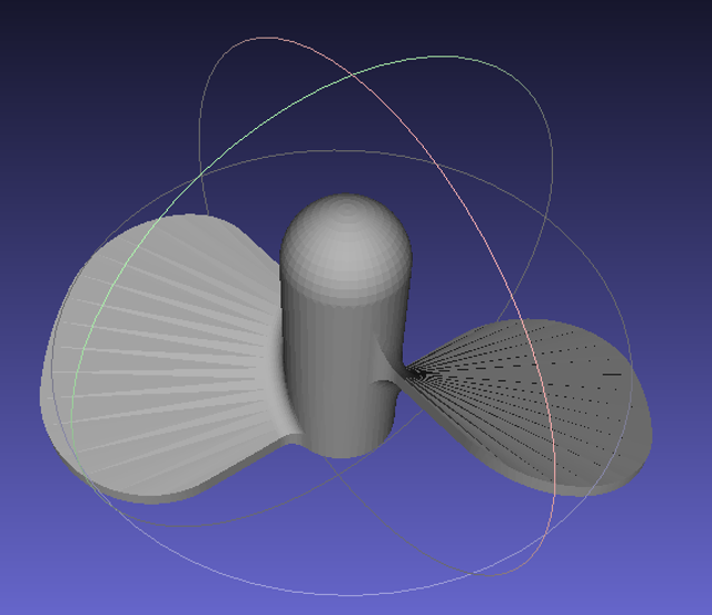
Then I printed using supports. I made various tests to obtain the ideal thickness such that not broken by separating the holders. 2mm thick was the best result.
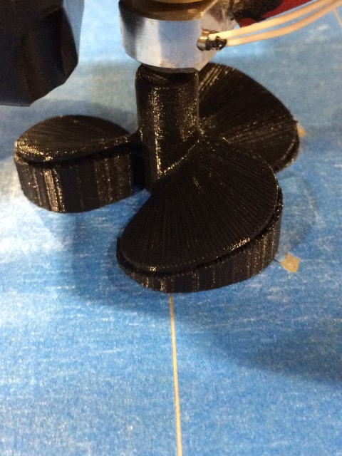
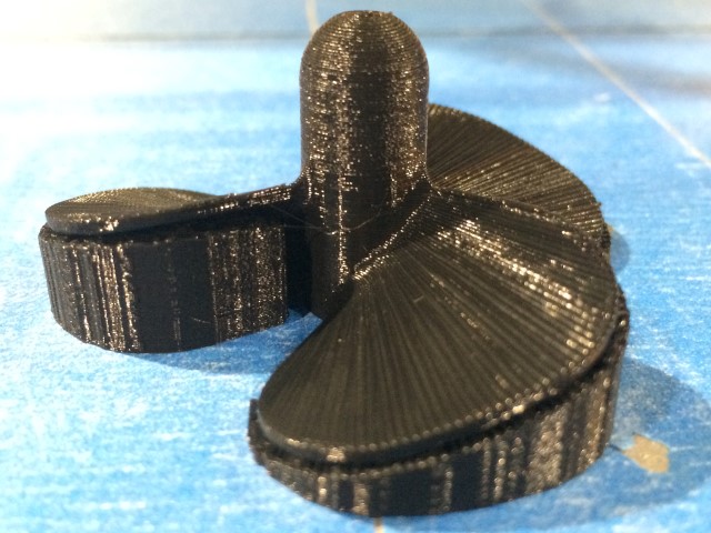
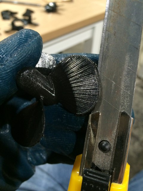
Failed tests.
Electronics and Programming
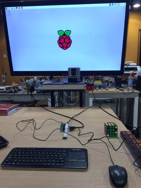
I am using the OS Raspbian Jessie in the Raspberry Pi, you can download it from the link below.
Raspbian Jessie
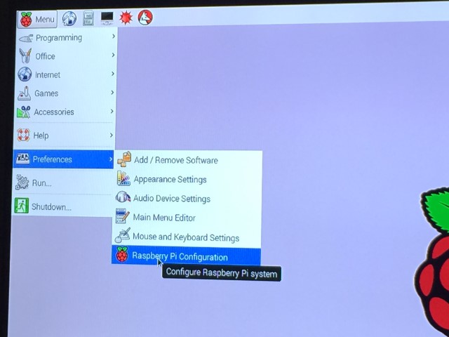
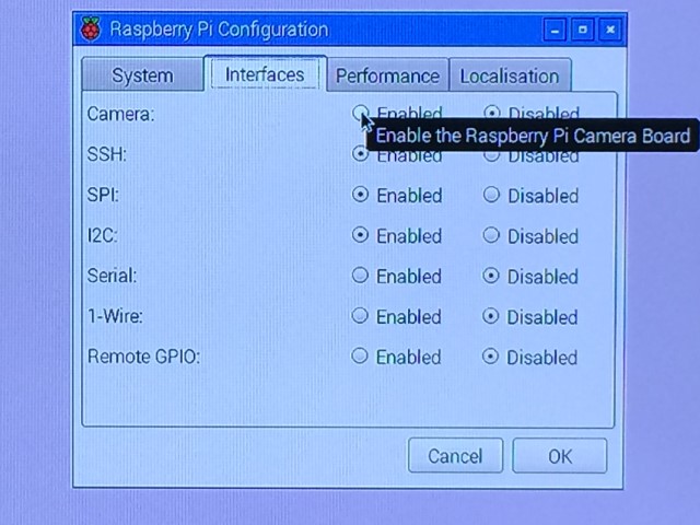
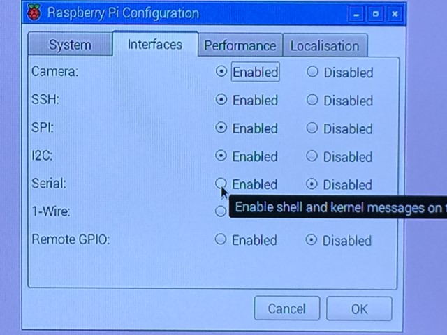
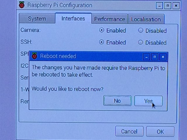
First I set the camera on the Raspberry Pi.
We must take the following steps to enable the camera and serial communication.
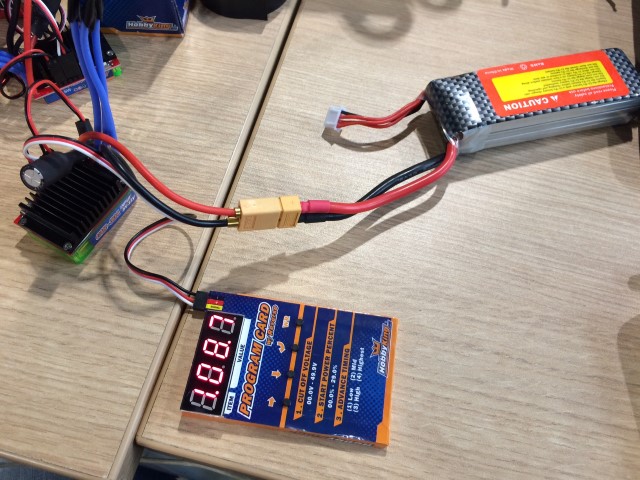
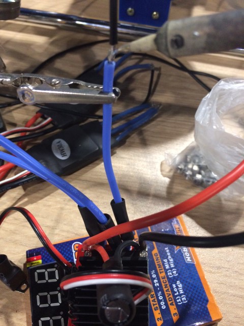
ESC configure using the program card.
You must set the voltage safety and operation of the direction of rotation as this is reverse speed controller.
Connect speed controllers with brushless motors and do tests using Arduino. To be sure it works step speed control code to FabDuino.
I do tests for reading the temperature sensor.
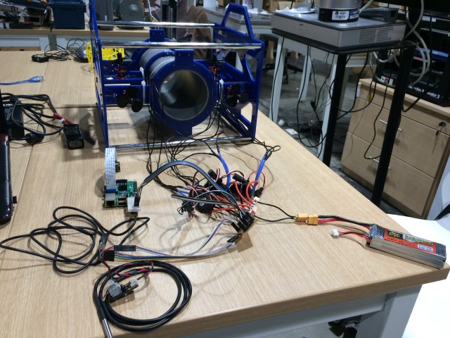
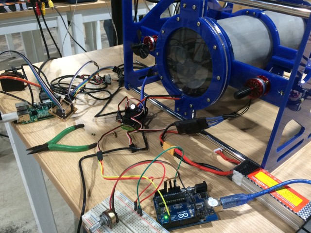
Finally I integrate everything.
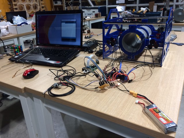
Integration testing of electronic components were successful.
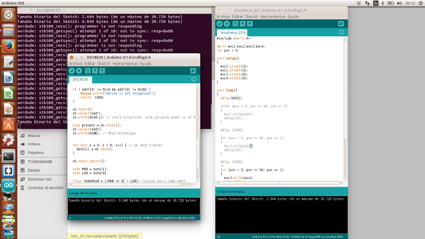
Arduino codes:
Testing Brushless Motors
											#include "Servo.h"


											Servo esc1,esc2,esc3,esc4;

											int pos = 0;


											void setup()

											{

												esc1.attach(3);

												esc2.attach(5);

												esc3.attach(6);

												esc4.attach(9);

											}


											void loop()

											{

												delay(5000);


												for (pos = 0; pos <= 50; pos += 1)

												{

													esc3.write(pos);

													delay(15);

												}


												delay (3000);


												for (pos = 0; pos <= 50; pos += 1)

												{

													esc4.write(pos);

													delay(15);

												}


												delay (3000);

											}
You have to download the library DFRobot to control the DS18B20 sensor from the following link:
Link
											#include "OneWire.h"


											int DS18S20_Pin = 2; //DS18S20 Signal pin on digital 2


											//Temperature chip i/o

											OneWire ds(DS18S20_Pin);  // on digital pin 2


											void setup(void) {

												Serial.begin(9600);

											}


											void loop(void) {

												float temperature = getTemp();

												Serial.println(temperature);


												delay(100); //just here to slow down the output so it is easier to read


											}


											float getTemp(){

												//returns the temperature from one DS18S20 in DEG Celsius


												byte data[12];

												byte addr[8];


												if ( !ds.search(addr)) {

														//no more sensors on chain, reset search

														ds.reset_search();

														return -1000;

												}


												if ( OneWire::crc8( addr, 7) != addr[7]) {

														Serial.println("CRC is not valid!");

														return -1000;

												}


												if ( addr[0] != 0x10 && addr[0] != 0x28) {

														Serial.print("Device is not recognized");

														return -1000;

												}


												ds.reset();

												ds.select(addr);

												ds.write(0x44,1); // start conversion, with parasite power on at the end


												byte present = ds.reset();

												ds.select(addr);

												ds.write(0xBE); // Read Scratchpad


												for (int i = 0; i < 9; i++) { // we need 9 bytes

													data[i] = ds.read();

												}


												ds.reset_search();


												byte MSB = data[1];

												byte LSB = data[0];


												float tempRead = ((MSB << 8) | LSB); //using two's compliment

												float TemperatureSum = tempRead / 16;


												return TemperatureSum;


											}
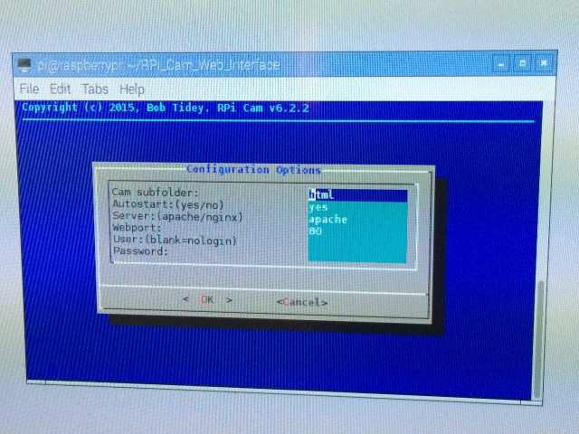
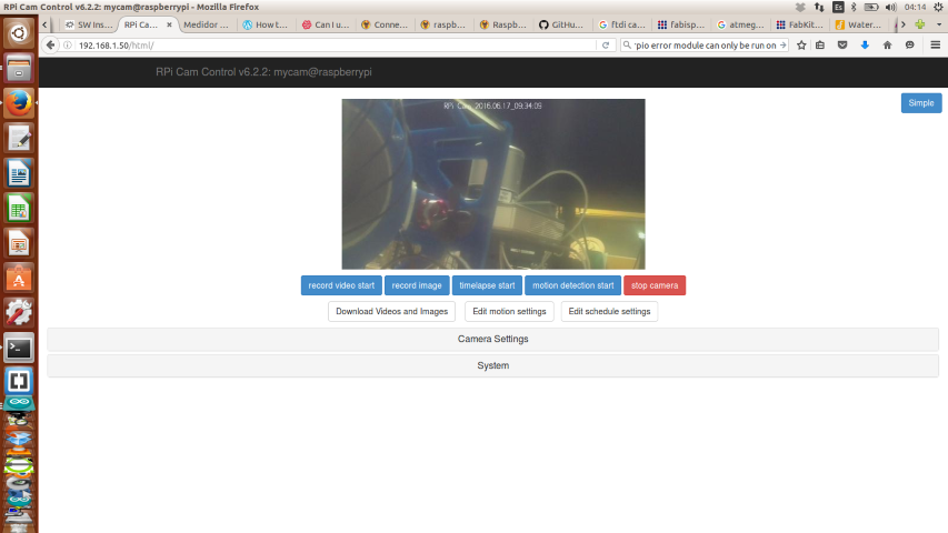
The best way to remotely monitor the Raspberry camera is using RPI-Cam-Web-Interface.
											sudo apt-get update

											sudo apt-get dist-upgrade


											git clone https://github.com/silvanmelchior/RPi_Cam_Web_Interface.git

											cd RPi_Cam_Web_Interface

											chmod u+x *.sh

											./install.sh
											sudo cp /boot/cmdline.txt /boot/cmdline.normal

											sudo nano /boot/cmdline.txt

											ip=192.168.1.50

											sudo cp /boot/cmdline.txt /boot/cmdline.direct
Finally, from a remote PC is entered into a browser the IP: 192.168.1.50/html/ and we can see the images transmitted by the camera.
Videos
Testing Brushless Motors
Testing Raspberry Camera
Testing Temperature Sensor
Conclusions
At this stage of development it was achieved finish building the structure and integrate electronic components also tested each of them.
The next step is to distribute the components inside the PVC tube and testing water filtration. The last stage will be to monitor and remotely
control the ROV submerged in a pool and then the sea.
Downloads
Code
3D Printing - Propellers
Laser Cutting - Acrylic Pieces
Presentation Slide
Video