Embedded programming
Have you:
- Documented what you learned from reading a microcontroller datasheet.
- - What questions do you have? What would you like to learn more about?
- Programmed your board
- Described the programming process/es you used
- Included your code
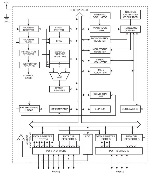
Documented what you learned from reading a microcontroller datasheet.
I worked with Attiny44 microcontroller ATMEL, you can download the data sheet from this link:
Datasheet Attiny44
Key parameters for ATtiny44:
- Flash (kBytes): 4 kBytes
- Pin Count: 14
- Max. Operating Freq. (MHz): 20 MHz
- CPU: 8-bit AVR
- # of Touch Channels: 6
- Max I/O Pins: 12
- Ext Interrupts: 12
- SPI: 1
- TWI (I2C): 1
- ADC Channels: 8
- ADC Resolution (bits): 10
- ADC Speed (ksps): 15
- ADC Gain Stage: Yes
- Analog Comparators: 1
- Temp. Sensor: Yes
- SRAM (kBytes): 0.25
- EEPROM (Bytes): 256
- Self Program Memory: Yes
- Temp. Range (deg C): -40 to 85
- I/O Supply Class: 1.8 to 5.5
- Operating Voltage (Vcc): 1.8 to 5.5
- Timers: 2
- Output Compare Channels: 4
- Input Capture Channels: 1
- PWM Channels: 4
- Calibrated RC Oscillator: Yes
- Watchdog: Yes
- Debug Interface: debugWIRE
According to this information, I can control up to 4 servo or DC motors (4 PWM), or read the signal up to 8 analog sensors (PORTA), or 12 digital signals (PORTA and PORTB).
Programmed your board and described the programming process/es you used
Arduino
I used the printed board designed in the assignment 6. You can program the PCB using the Arduino IDE. The following is required:
- FabISP programmer
- FTDI cable
FabISP driver
FTDI driver
Download Arduino IDE from Here.
Install support for "Attiny" controllers. I recommend following this Tutorial, it is compatible with the current version: 1.6.7.
Code to toggle LEDs by pressing the push button:
										void setup() {

											// put your setup code here, to run once:

											pinMode(3, OUTPUT);

											pinMode(7, OUTPUT);

											pinMode(2, INPUT);

										}


										void loop() {

											// put your main code here, to run repeatedly:

											if(digitalRead(2) == LOW)

											{

												digitalWrite(3, HIGH);

												digitalWrite(7, LOW);

											}else

											{

												digitalWrite(3, LOW);

												digitalWrite(7, HIGH);

											}

										}
- Board: "ATtiny"
- Processor: "ATtiny44"
- Clock: "20MHz (external)"
- Programmer: "USBtinyISP"
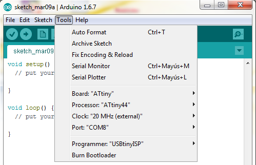
Turn up the code and test PCB. You will see that an LED is on and the other off, pressing the pushbutton the LED goes on and off is turned on.
Atmel Studio
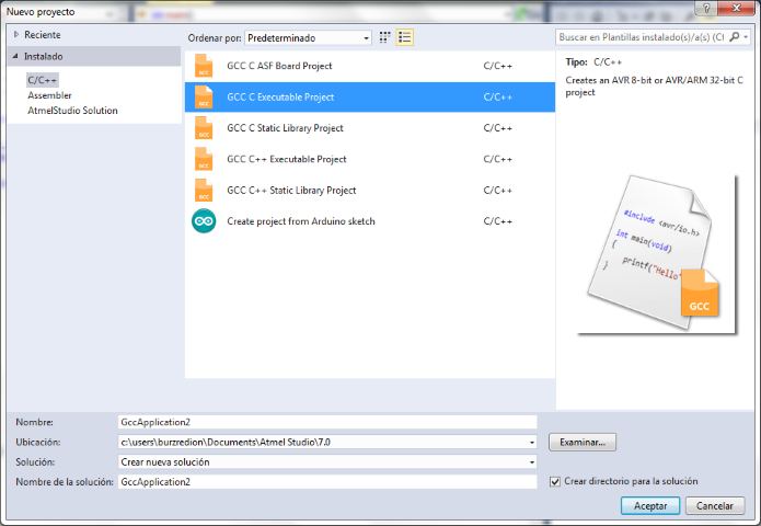
Step 1: Create a new project on AtmelStudioFile>>New>>Project
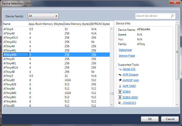
Choose the device
Step 2: Type the following code
#define F_CPU 20000000UL
#include
#include
int main() {
DDRA |= (1 << PA3)|(1 << PA7);
DDRA &= ~(1 << PA2);
while (1)
{
if((PINA & (1<
PORTA |= (1 << PORTA3);
PORTA &= ~(1 << PORTA7);
}
else
{
PORTA &= ~(1 << PORTA3);
PORTA |= (1 << PORTA7);
}
}
}
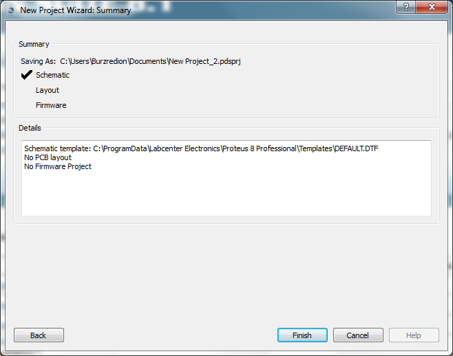
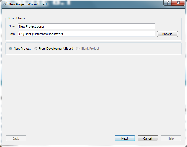
<Step 3: Create a new project on Proteus
File>>New Project
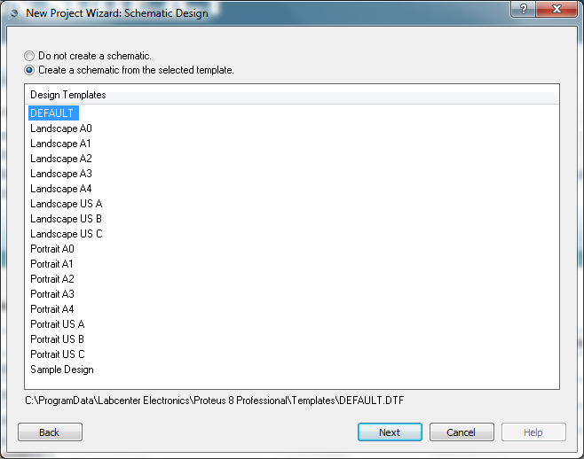
Create a schematic from the selected template
Do not create a PCB layout
No Firmware Project
New Project Wizard: Summary