Input Devices
Have you:
- Described your design and fabrication process using words/images/screenshots
- Explained the programming process/es you used and how the microcontroller datasheet helped you
- Explained problems and how you fixed them
- Included original design files and code
Described your design and fabrication process using words/images/screenshots
The Sensor
A1324
Datasheet
Is a Linear Hall Effect Sensor with Analog Output, provide a voltage output that is proportional to the applied magnetic field. It has a programmed sensitivities of 5.0 mV/G. It can be used in applications such as displacement, angular position, and current measurement.

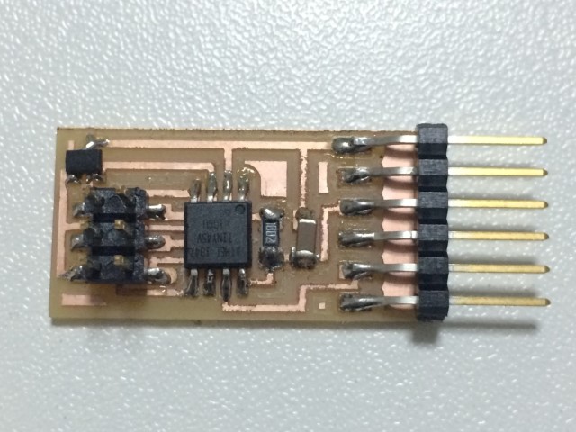
BOM
We need the following components:- (01) IC A1324
- (01) IC Attiny45
- (01) Resistor 10k
- (01) Capacitor 1uF
- (01) Connector 2x3
- (01) Connector 1x6
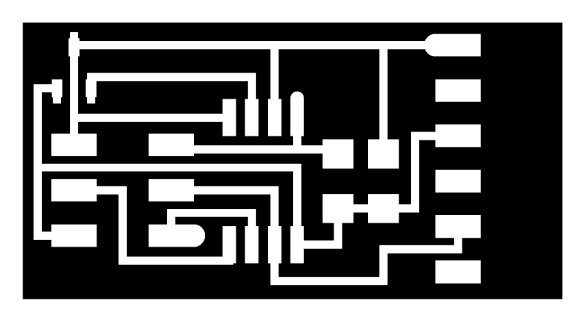
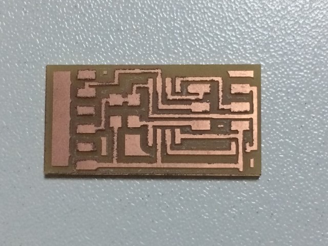
Schematics and PCB
I had many problems trying to design a PCB for an acceleration sensor due to its dimensions. So I chose to reproduce the Neil's pcb for magnetic sensor.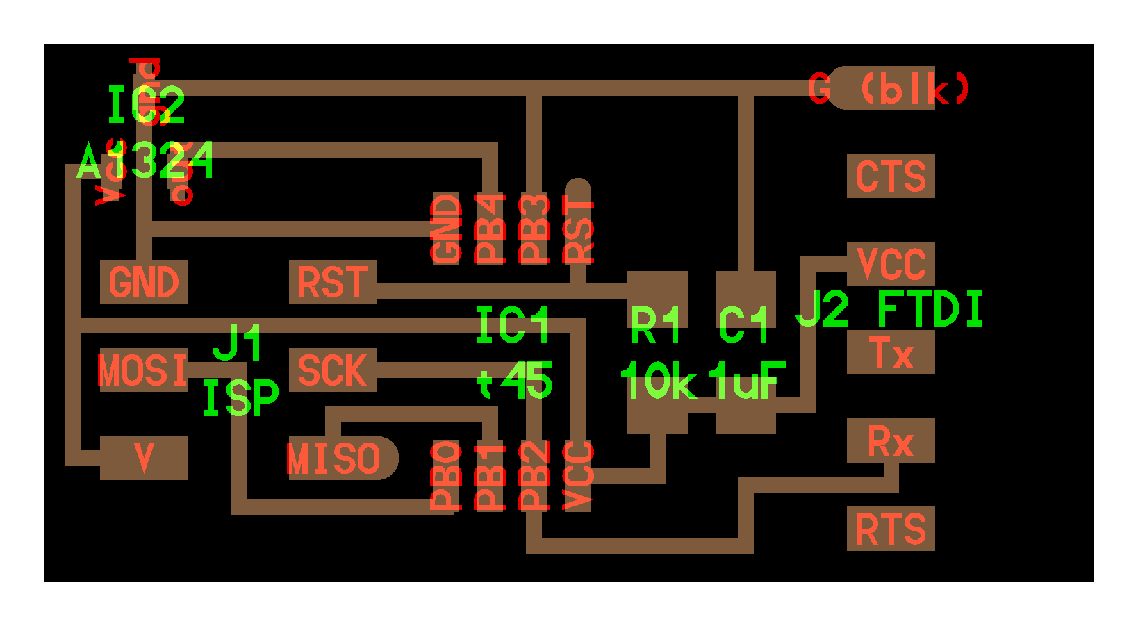
I used the following files:

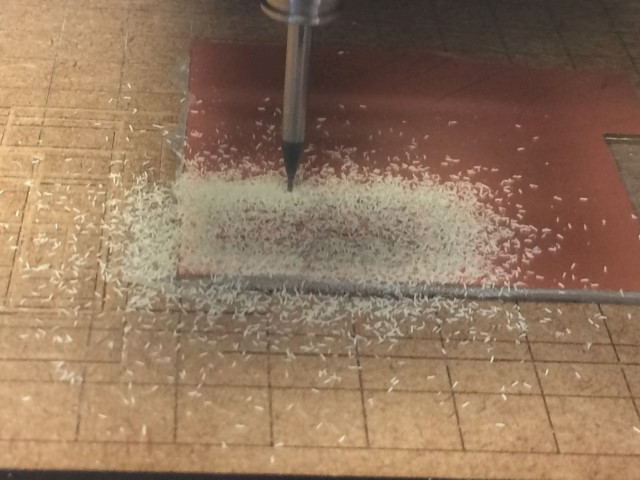
I followed the same procedure in Assignment 4.
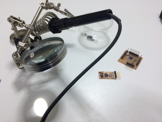
Explained the programming process/es you used and how the microcontroller datasheet helped you
To program the board is required ATtinyUSB programmer and FTDI cable and then the commands shown in the following code:
											burz@ENIAC:~/Documentos/FabAcademy/Assignment_11$ sudo make -f hello.mag.45.make program-usbtiny

											[sudo] password for burz:

											avr-objcopy -O ihex hello.mag.45.out hello.mag.45.c.hex;\

											avr-size --mcu=attiny45 --format=avr hello.mag.45.out

											AVR Memory Usage

											----------------

											Device: attiny45


											Program:     662 bytes (16.2% Full)

											(.text + .data + .bootloader)


											Data:          6 bytes (2.3% Full)

											(.data + .bss + .noinit)


											avrdude -p t45 -P usb -c usbtiny -U flash:w:hello.mag.45.c.hex


											avrdude: AVR device initialized and ready to accept instructions


											Reading | ################################################## | 100% 0.00s


											avrdude: Device signature = 0x1e9206

											avrdude: NOTE: "flash" memory has been specified, an erase cycle will be performed

															 To disable this feature, specify the -D option.

											avrdude: erasing chip

											avrdude: reading input file "hello.mag.45.c.hex"

											avrdude: input file hello.mag.45.c.hex auto detected as Intel Hex

											avrdude: writing flash (662 bytes):


											Writing | ################################################## | 100% 0.85s


											avrdude: 662 bytes of flash written

											avrdude: verifying flash memory against hello.mag.45.c.hex:

											avrdude: load data flash data from input file hello.mag.45.c.hex:

											avrdude: input file hello.mag.45.c.hex auto detected as Intel Hex

											avrdude: input file hello.mag.45.c.hex contains 662 bytes

											avrdude: reading on-chip flash data:


											Reading | ################################################## | 100% 1.39s


											avrdude: verifying ...

											avrdude: 662 bytes of flash verified


											avrdude: safemode: Fuses OK (E:FF, H:DF, L:62)


											avrdude done.  Thank you.


											burz@ENIAC:~/Documentos/FabAcademy/Assignment_11$ python hello.mag.45.py /dev/ttyUSB0

Test
You can have readings between 0 and 1023 (10 bit resolution). Depending on the polarity of the magnet can have readings between 0 and 511 or 512 and 1023.
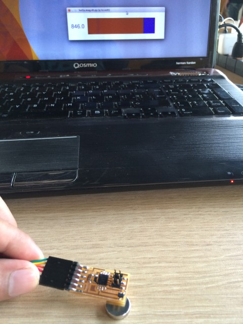

Here is a video showing the operation of the printed circuit board for the Hall effect sensor.
You can see that by bringing the electronic board to the magnet increase or decrease the output values depending on the polarity.
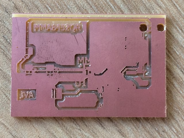
Explained problems and how you fixed them
I tried to design a printed circuit board for use with an accelerometer, but the CNC machine could not drilling it for not having
a drill smaller than 1/64. The sensor MMA8452QR is very small to manufacture with the technology that we have in our lab so I
had to make the board for the hall effect sensor.