Embedded programming
In this assignment , I'll use attiny44A and FPGA, for programing
Electronics Components
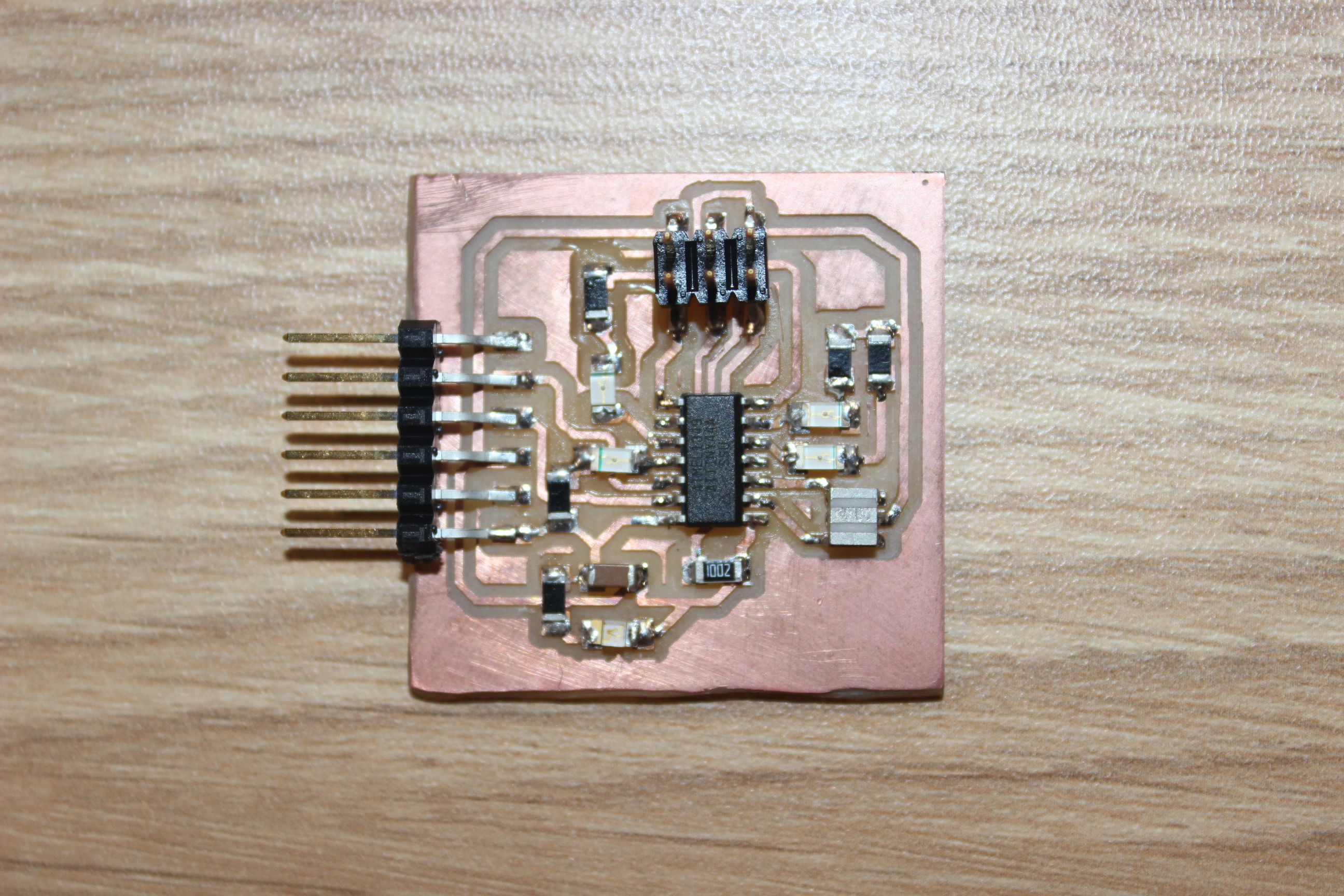
1.-Attiny 44A board
SOFTWARE
2.-eagle
3.-Fabmodule
4.-atmel studio 6.2
5.-arduino IDE
MACHINES
6.-ROland Modela

After read the datasheet,I conclude ,we can make many digital applications and analogic too but with some limitations, I put then the most important parameters in my opinion and some kind of projects we can make:
operating voltage : 1.8v-5.5v
4kBytes Flash memory
256 SRAM
10bits ADC
internal calibrate Oscillator
Speed grade 0-10MHz (2.7v-5.5v)
Have a interrumpt unit
ISP Programing
The basic caracteristics of this board are datasheet
50MHz Frecuency
4320 logic cell equivalents
Twelve 18k-bit block RAMs (216K bits)
adicional important modules
3-bit, 8-color VGA display port
9-pin RS-232 Serial Port
push buttons
LEDs
Switchs
with this board we can make high speed processes, in these case we'll make a PWM with diferent frequencies
and then we are going to send the PWM signal to H bridge who is going to controlling the motor
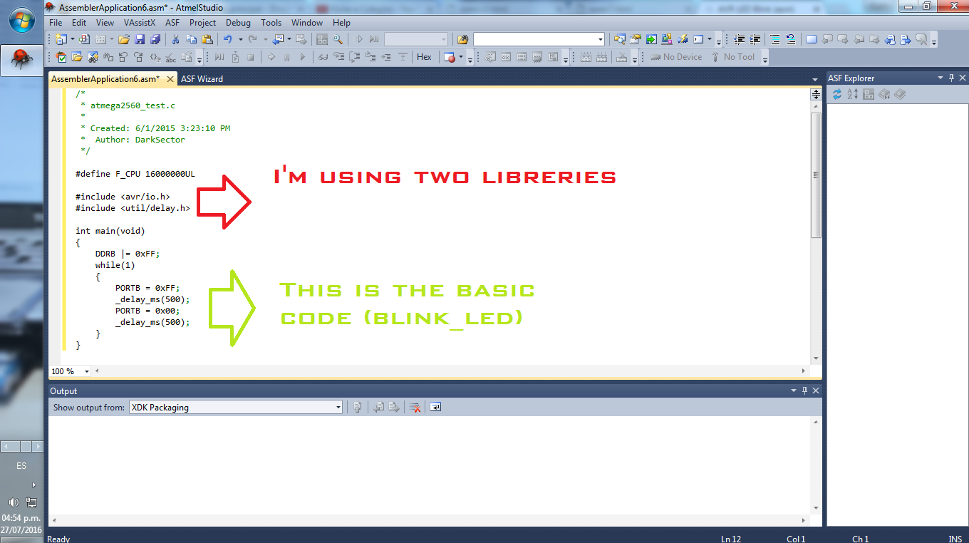
first perform tests performed atmel studio compilations code in C, to program needed more knowledge of C code for uC ATMEL, this will make the AVRISP MKII and runs smoothly ,( C code_atmelStudio)I further testing this software for the task of INPUTs, did tests to program in ATMEL STUDIO, using the FABisp, more tests at ATMEL STUDIO

as a second test using the Arduino IDE for this I had to add the list following this tutorial ATtiny Microcontrollers (TUTORIAL) also,I gave a class to my partners to using arduino ID and programing (Arely)
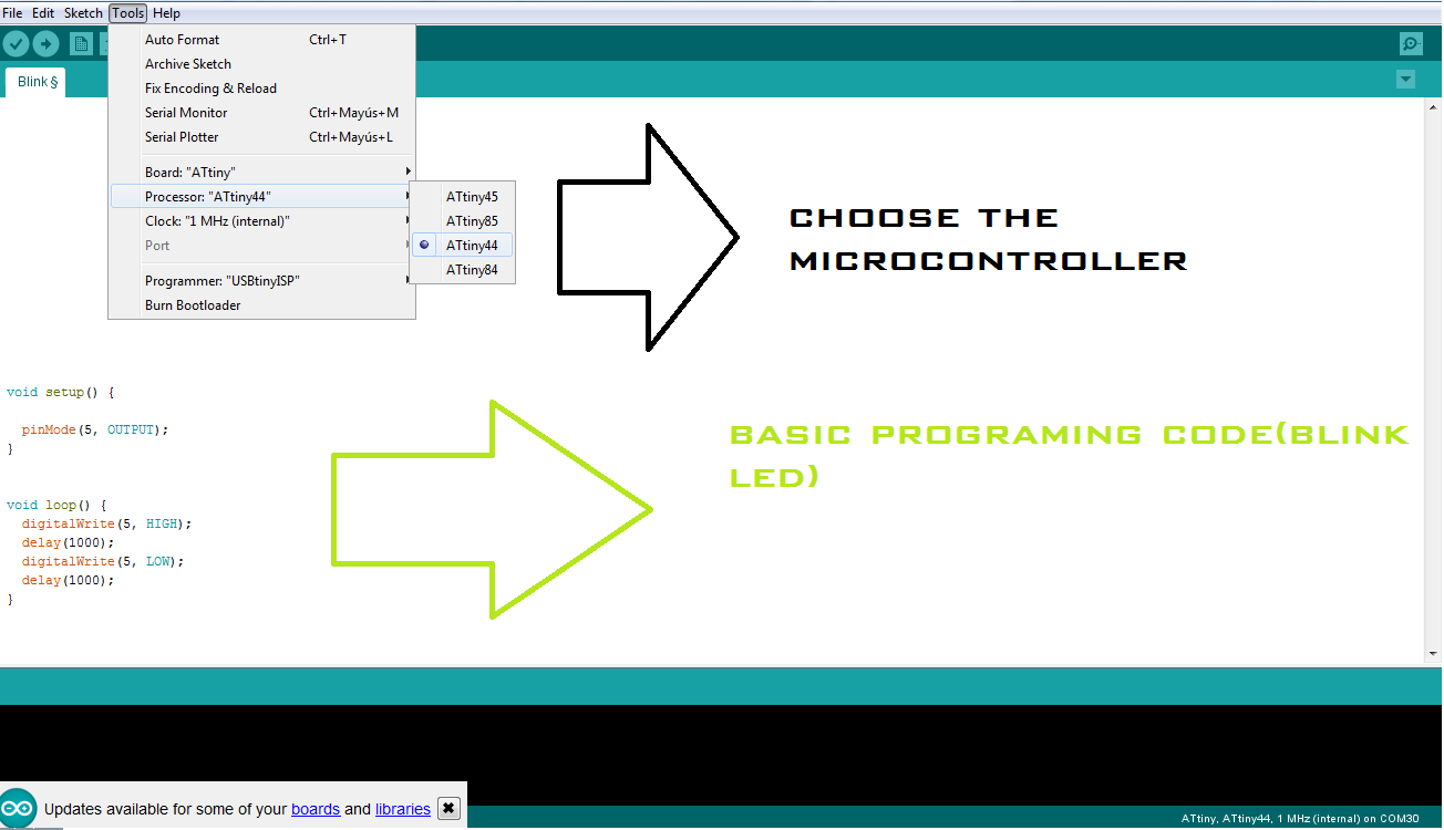
to use the Arduino IDE arduino had to use the card as a programmer for it I followed the following tutorial (TUTORIAL) then I could make use of the examples of the IDE in principle only perform tests with LEDS told by my PCB
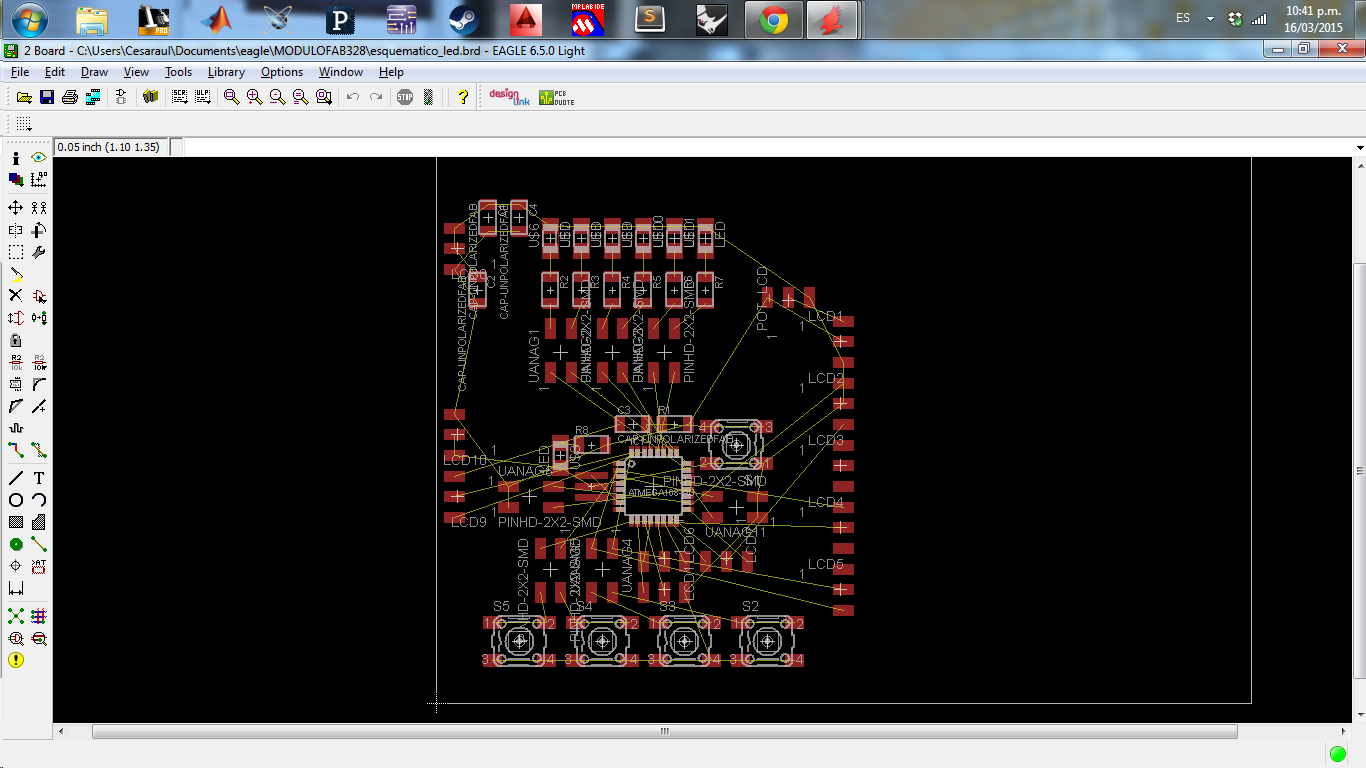
Due to the limited applications that could develop in my PCB ATtiny decided to do my own training module is currently in the state showing the image features buttons, leds, lcd 2x16 connector port connectors for analogPCB design
In this task we just turn on and off a LED in different programming languages, I tried different programming environments such as Atmel Studio IDE ARDUINO, with the help of tutorials,in the video we just can see the basic blink programing code
example codes, I used ( DOWNLOAD Assembler code )

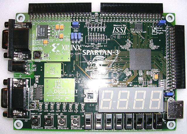
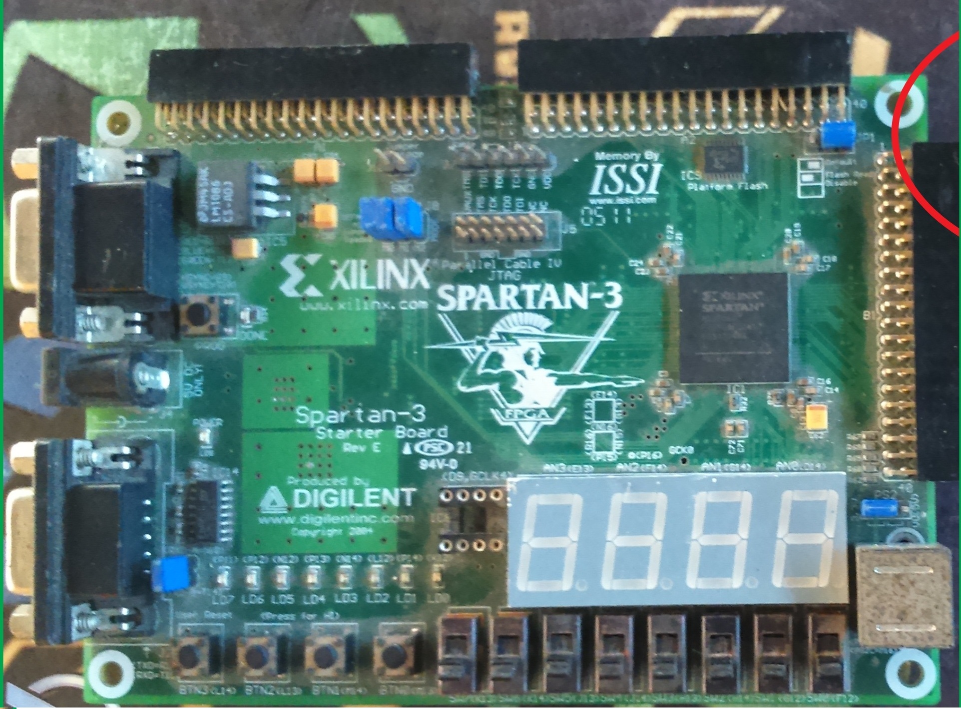
Now I will program the FPGA, I will use to program XILINX ISE and VHDL language, the application will be simple, for use in following assignments

I will build a PWM signal inputs controlled switches, for regulating the speed of a DC motor,I will use the PWM signal to regulate the power to feed the load by 50%, 25% and 75%, this will be the percentage of dutycicle,I'll use the FPGA will be a SPARTAN 3 having a frequency of 50MHz
I will use 3 switch as input and digital output for the PWM

I maked a frecuency divider for build a PWM signal, I make a circuit for controlet a DC motor, in my assignamment of output
(VHDL code )
(OUTPUT)
50MHz Frecuency
4320 logic cell equivalents
Twelve 18k-bit block RAMs (216K bits)
adicional important modules
3-bit, 8-color VGA display port
9-pin RS-232 Serial Port
push buttons
LEDs
Switchs
with this board we can make high speed processes, in these case we'll make a PWM with diferent frequencies and then we are going to send the PWM signal to H bridge who is going to controlling the motor
first perform tests performed atmel studio compilations code in C, to program needed more knowledge of C code for uC ATMEL, this will make the AVRISP MKII and runs smoothly ,( C code_atmelStudio)I further testing this software for the task of INPUTs, did tests to program in ATMEL STUDIO, using the FABisp, more tests at ATMEL STUDIO
as a second test using the Arduino IDE for this I had to add the list following this tutorial ATtiny Microcontrollers (TUTORIAL) also,I gave a class to my partners to using arduino ID and programing (Arely)
to use the Arduino IDE arduino had to use the card as a programmer for it I followed the following tutorial (TUTORIAL) then I could make use of the examples of the IDE in principle only perform tests with LEDS told by my PCB
Due to the limited applications that could develop in my PCB ATtiny decided to do my own training module is currently in the state showing the image features buttons, leds, lcd 2x16 connector port connectors for analogPCB design
In this task we just turn on and off a LED in different programming languages, I tried different programming environments such as Atmel Studio IDE ARDUINO, with the help of tutorials,in the video we just can see the basic blink programing code
example codes, I used ( DOWNLOAD Assembler code )
Now I will program the FPGA, I will use to program XILINX ISE and VHDL language, the application will be simple, for use in following assignments
I will build a PWM signal inputs controlled switches, for regulating the speed of a DC motor,I will use the PWM signal to regulate the power to feed the load by 50%, 25% and 75%, this will be the percentage of dutycicle,I'll use the FPGA will be a SPARTAN 3 having a frequency of 50MHz
I will use 3 switch as input and digital output for the PWM