MATERIALS
1.-PLA
2.-ABS
SOFTWARE
3.- Inventor
4.-makerdesktop
5.-Arduino IDE
6.-skanect
7.-Fabmoduls
MACHINES
8.-3D printer Replicator 2 - makerbot
9.-Epilog Laser mini
10.-Roland Modela MDX-20
ELECTRONIC COMPONENT
11.-RF Module
12.-AVR 328
13.-serv Motor(4) 180°
14.-switchs and Buttons
15.-Resistors and capacitors
16.-voltage Regulator
17.-Battery
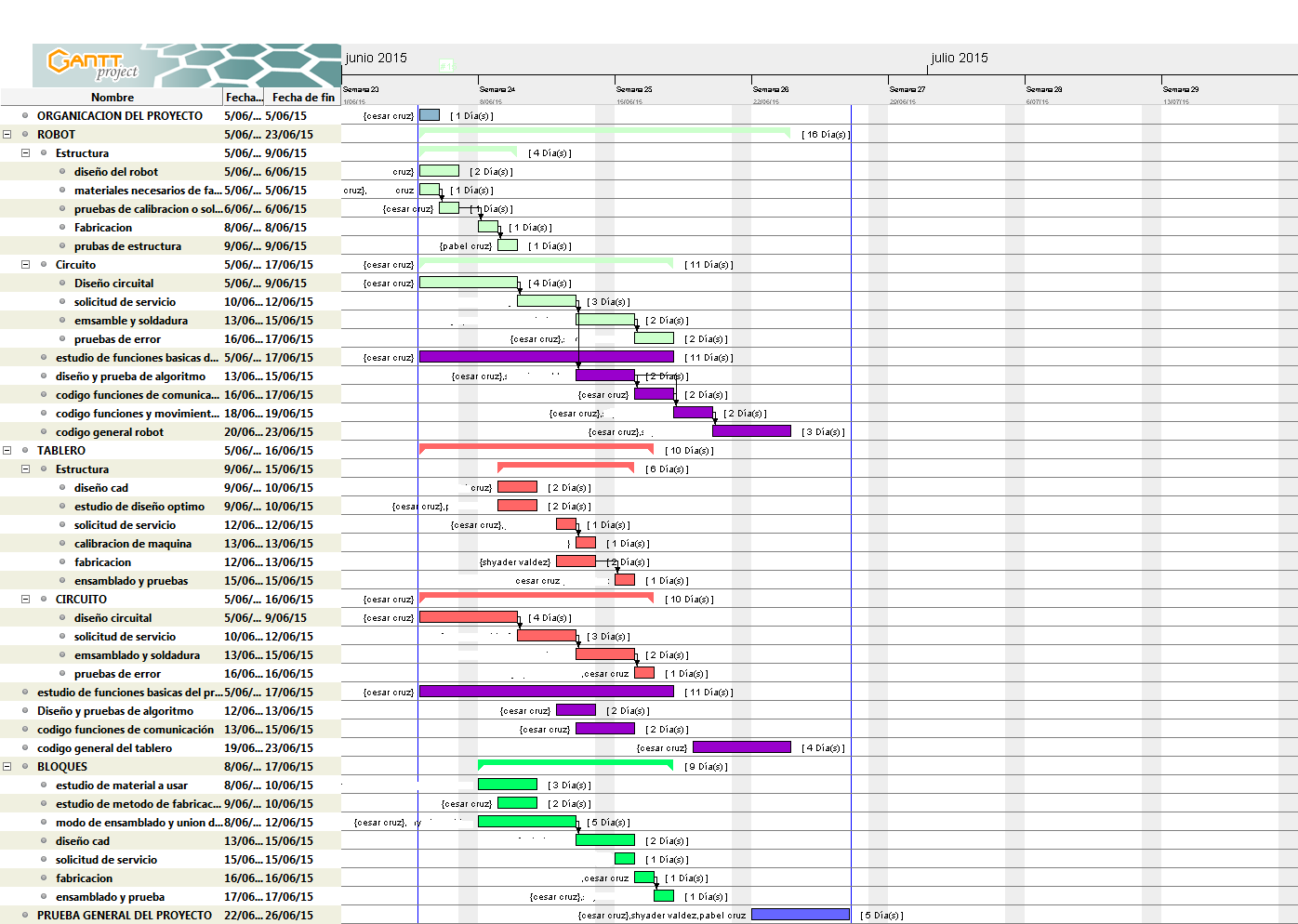
I followed the next plan for manage and develop my project
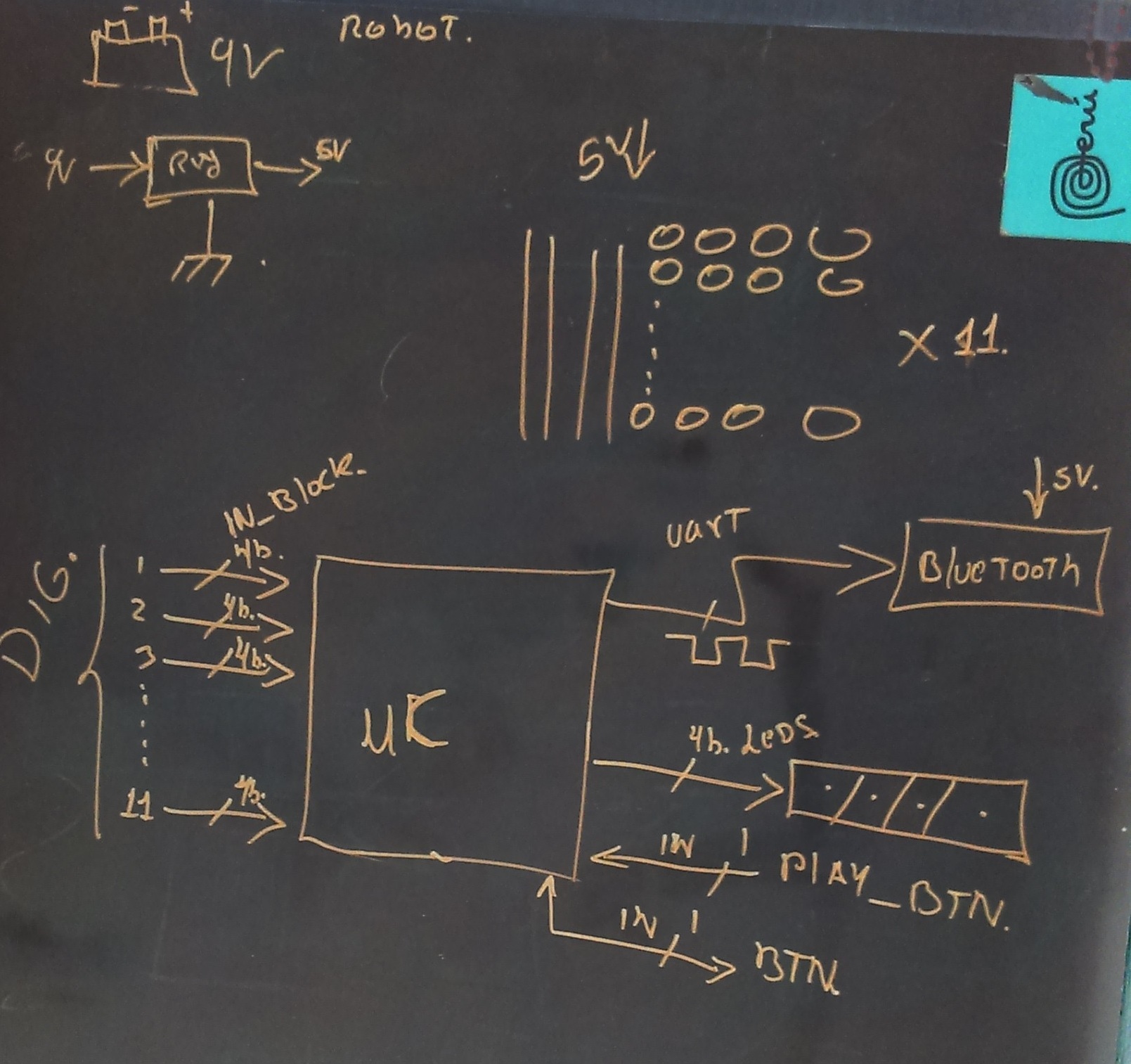
My first step was to make a general outline of the project components, in this case show the outline of the box programming, which have clear that receive as inputs 4 bits that vary from the blocks placed; there's the lap top communication that initially bluetooth but was later changed to mind the RF, also I appointed entries from buttons
Then do the scheme of the robot, where the outputs for 4 servo motors, which will be controlled by PWM, the RF communication is shown, the voltage regulator 9 to 5v
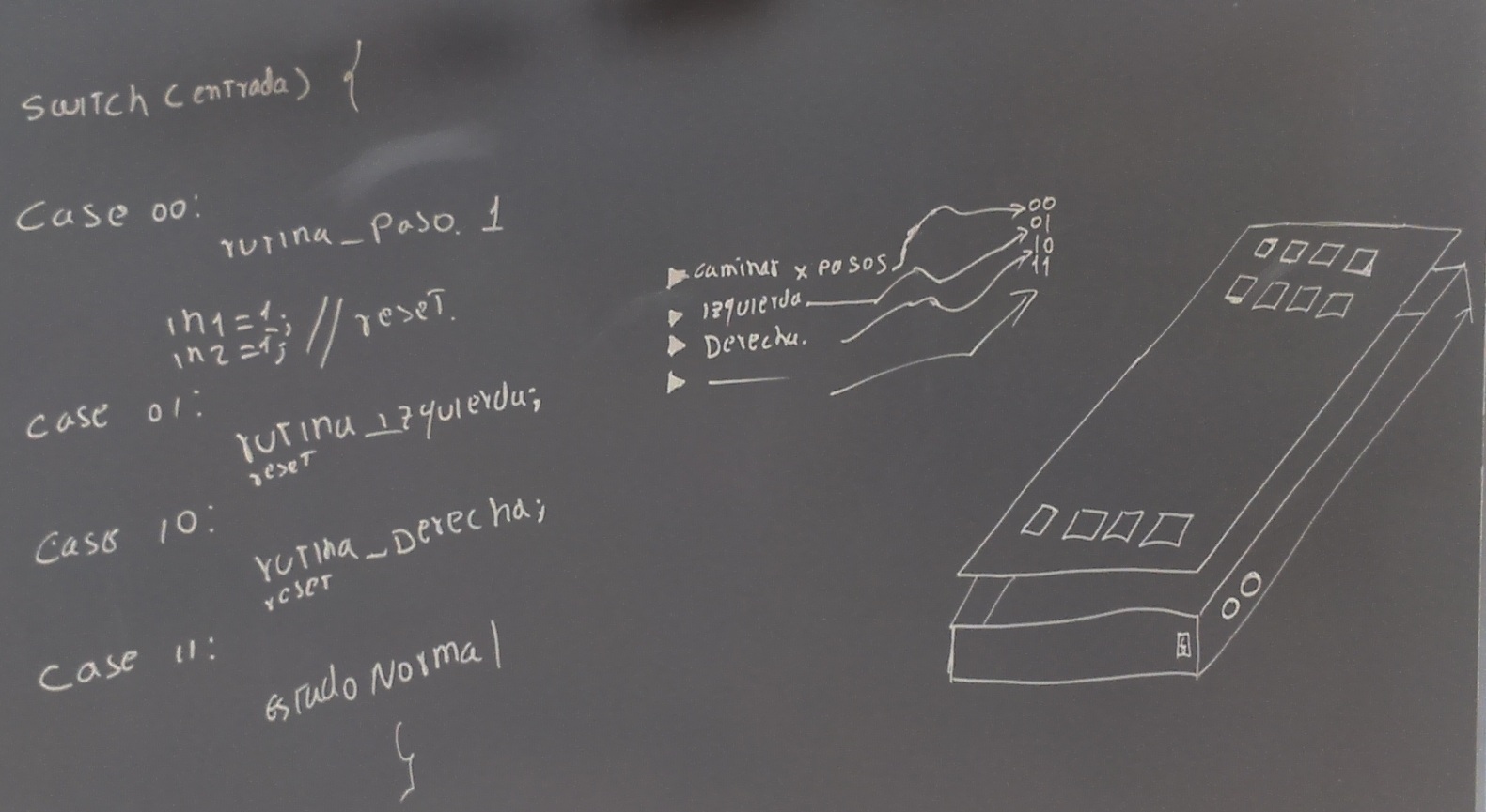
In order to define the shape of the box programming, I define the basic algorithm and basic instructions; it will be a "switch statement" that receive digital inputs placed on the board and change with each block
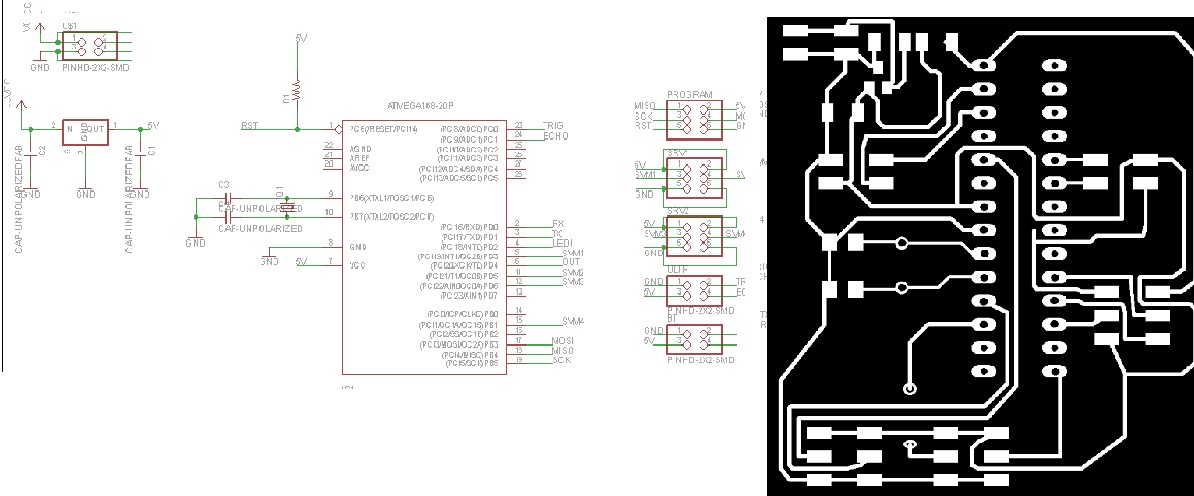
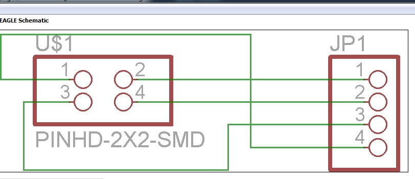
Once the sketches done, perform design circuits to generate the image eagle and manufacture it in machine "models", I share the circuit at the end
Then I designed a simple circuit,for recive the digital inputs from the blocks, this circuit is for any point in the programing board
he placed the input circuits on the base of the main block and put wires to get the information to the microcontroller,Box'll receive all the information will be a mega arduino, as I have several digital inputs, for this prototipe
Im going to use , just 11 inputs and 3 basic instruccions, then I want to use more inputs for send more instrucctions
the other major component of the project is the robot can walk through the 4 servo motors, the ultrasonic sensor is not being used, but will be used in later, inside the robot it has a 9V battery that powers the main circuit before designed the design files of the robot are in the next link ( DOWNLOAD )
I tested the algorithm for walking robot, mainly to turn right and left that are the basic instructions that will for now
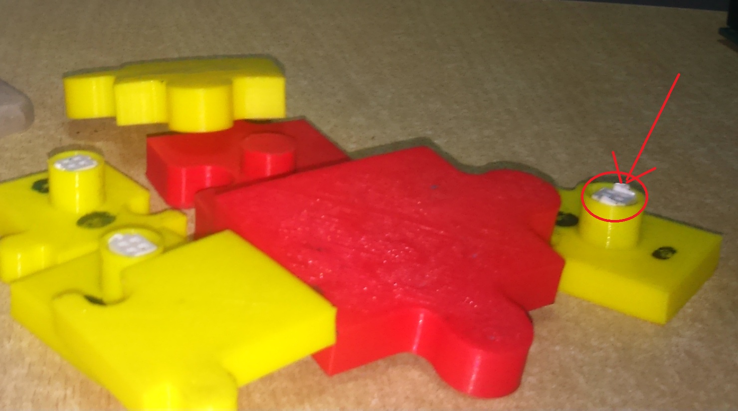
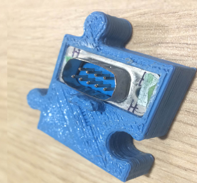
for the design of the blocks perform a simple design, with the typical form of puzzles, inside a connector which varies the polarity of the pins for digital input vary each variation involves a new command and the board will recognize
These are the parts of my final project, whose operation is to place the blocks with instructions in order from top to bottom once placed the button is pressed to send the information to the command for the robot, makes RF communication via the instructions are only 3 walking, walk left, walk right, I had limitations in the amount of cable you would need to use all the entries from the board, but in the later will use a base of PCBs to avoid the problem of cables
COMMENTS:
-project difficulties arose from my lack of experience in the areas of design and CAD tools use simple designs to the project prototype
-I believe that the main part of the project is the algorithm that has the programming board
-I will continue working on the project, because I think that is a market that can be exploited
recommendations:
This project was inspired by the scratch software, to encourage and instroducir children within the program, on stage is the project's basic functions if you want to replicate the project considered, the materials were chosen to achieve a lower price
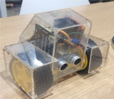
I have continued to make rapid prototyping of my project to improve, in this case change the robot by a vehicle designed in acrylic, in this case I'm using wheels,this allows me to add more instructions for programming
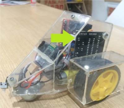
in this case I have designed a new plate using the microcontroller avr328, I share the schematic and BRD at the following link ( DOWNLOAD )
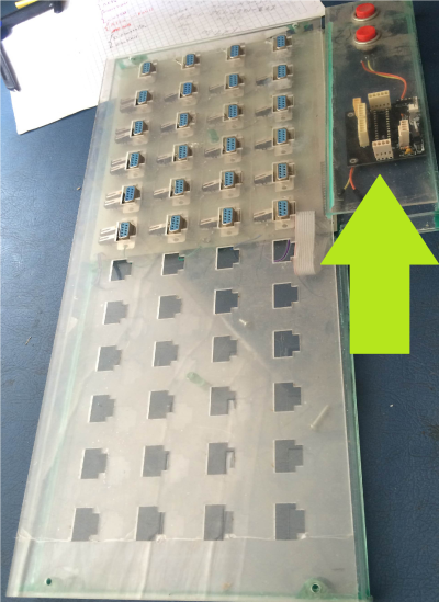
I have also designed a new board using DB9 connectors to increase the number of connections, I decided to make a large PCB, to specify the measures( DOWNLOAD )
as a result of changing the board, I had to change the shape of the blocks, placing DB9 male connectors
I am planning to change the initial control circuit, for this I will use the circuit designed for the robot using the AVR microcontroller 328p,for this I have to improve programming codes, I will continue working on my project to improve and to make tests with children