Networking and communications
In this task, I made 2 applications , First I used I RFmodule,after that ,I designed the circuits for serial communication, the master and the slave
Materials
1.-(2) Arduino Board "I used Uno"
2.-RF 315MHz transmitter-receiver module .
3.-BreadBoard.
4.- jumper wire .
5.-(2) Attiny 45
6.-PBC
7.-electronics components
8.-wires
SOFTWARE
9.-Arduino IDE
10.-Eagle CADsoft
Machines
11.-ROLAND MODELA

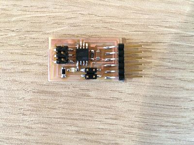
This circuit recive the data from the computer for that we needed to at a FTID conector for connect the USB wire, all the process did attiny45 , after recive the data,this master circuit send the data to slave circuit , ( Schematic )and ( BRD ) for milling

This last circuit receive the data from Master circuit, in this case I don't needed the FTID connector, only RX and TX wires from Master circuit( Schematic )and ( BRD ) for milling

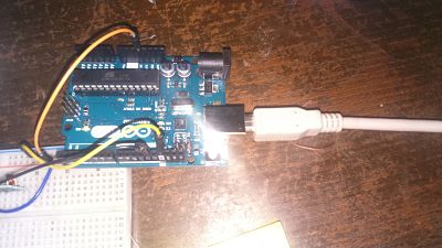
In this case I tried a commercial RF module
Working voltage: 5V
Working current: max Less than 40mA max , and min 9mA
Resonance mode: (SAW)
Modulation mode: ASK
Working frequency: Eve 315MHz
Transmission power: 25mW (315MHz at 12V)
Frequency error: +150kHz (max)
Velocity : less than 10Kbps
Receiver :
Working voltage: 5.0VDC +0.5V
Working current:≤5.5mA max
Working method: OOK/ASK
Working frequency: 315MHz
Bandwidth: 2MHz
Sensitivity: excel –100dBm (50Ω)
Transmitting velocity: 9.6Kbps (at 315MHz and -95dBm)

for Transmitter :
Vcc >>>>5V
ATAD>>>D12"You can change it as you like from Software" .
Gnd >>> Gnd
Receiver :
Vcc>>>>5V
Data>>>D12
Gnd>>>Gnd

I used VirtualWire Librery, this library use a Timer1 for build
ASK modulation, for used it we have to download the librery and move it to "libreries" in to arduino folder
My test code ( DOWNLOAD )
VirtualWire Librery ( DOWNLOAD )

I just send characters for test the comunications and I can see the characters with the serial comunication window. I going to used this modulo and this comunication in my final proyecto so, this was test
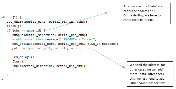
After testing the RF modules, I tested with the serial circuit MASTER AND SLAVE and 2 nodes, using the ATtiny 45 for each one, the next diagram explaim how it's work this little network
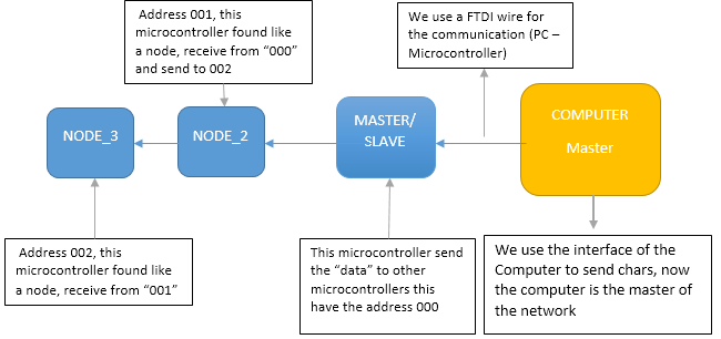

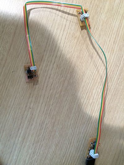
The network is composed of three nodes that are connected
Here I explaim the code and how it's work with each node,I just change the ID
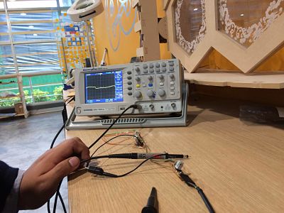
to verify communication perform basic tests on the oscilloscope
Tests made using the Arduino IDE, transmitting characters char
To check the transmission, I used an oscilloscope, perform simple tests, as shown in sending video characters char and the pulse width varies depending on the amount of information sent, you can not appreciate in detail the characteristic of the signal on the oscilloscope,then I can not analyze information
My code,is in base of code of classes, I edited on Atmelstudio ( DOWNLOAD )